
 Since ancient times people admired the music box. Their creation was only very skilled mechanics, who had besides an ear for music. Now the progress of technology made it easier. Electronic box whose schema is shown in figure 1, may collect even the ham is not very high qualifications. But a musical ear is still required.
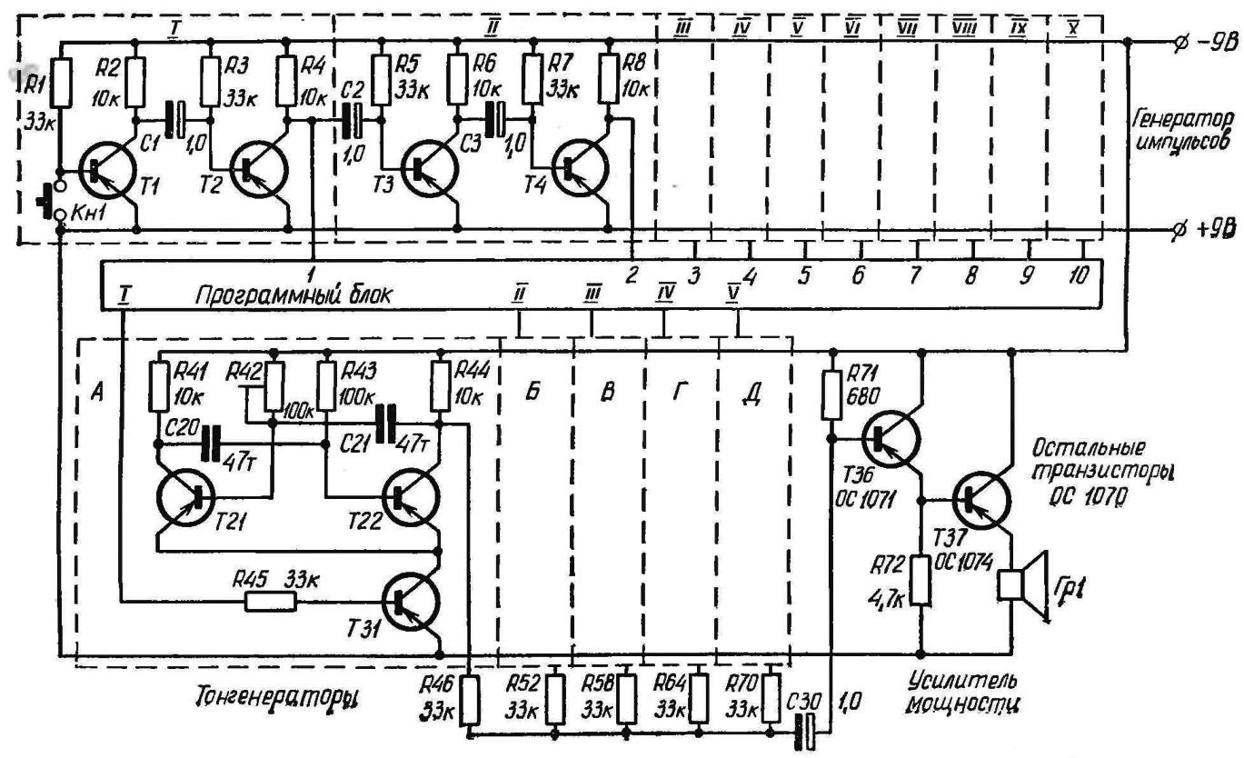
The operation of the circuit controlled by the pulses coming from the generator transistors T1—T20. This generator generates ten pulses after we click and release the button KN1.
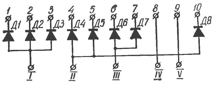
The tone generators are assembled according to the scheme of the multivibrator transistors T21—T30. The sequence generators enable control pulses to create a melody is determined by the scheme of the program block. Diagram of the unit to the tune of “La Marseillaise” is shown in figure 2. Connection using connector blocks with different programs makes it easy to change ringtones.
The frequency of the individual tone generators are set by the relevant trimmer R 100 kω.
The scheme can also be used as a musical call bell that chimes.
The OS transistors 1070, 1071 OS, OS 1074 may be replaced respectively by transistors МП39 domestic, ГТ108А(B), МП25Б.
Recommend to read
 CASE-UNIVERSAL
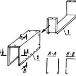
For many years I use in my Amateur designs of a homemade hull, made by our own technology. I would be glad if it will embrace readers and respected magazine. The housing type...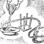 VACUUM CLEANER-FAN
Forest dwellers often have difficulties in the processing of cranberries, blueberries, cranberries. But a great helper in this case may be an ordinary vacuum cleaner. You only need one...
