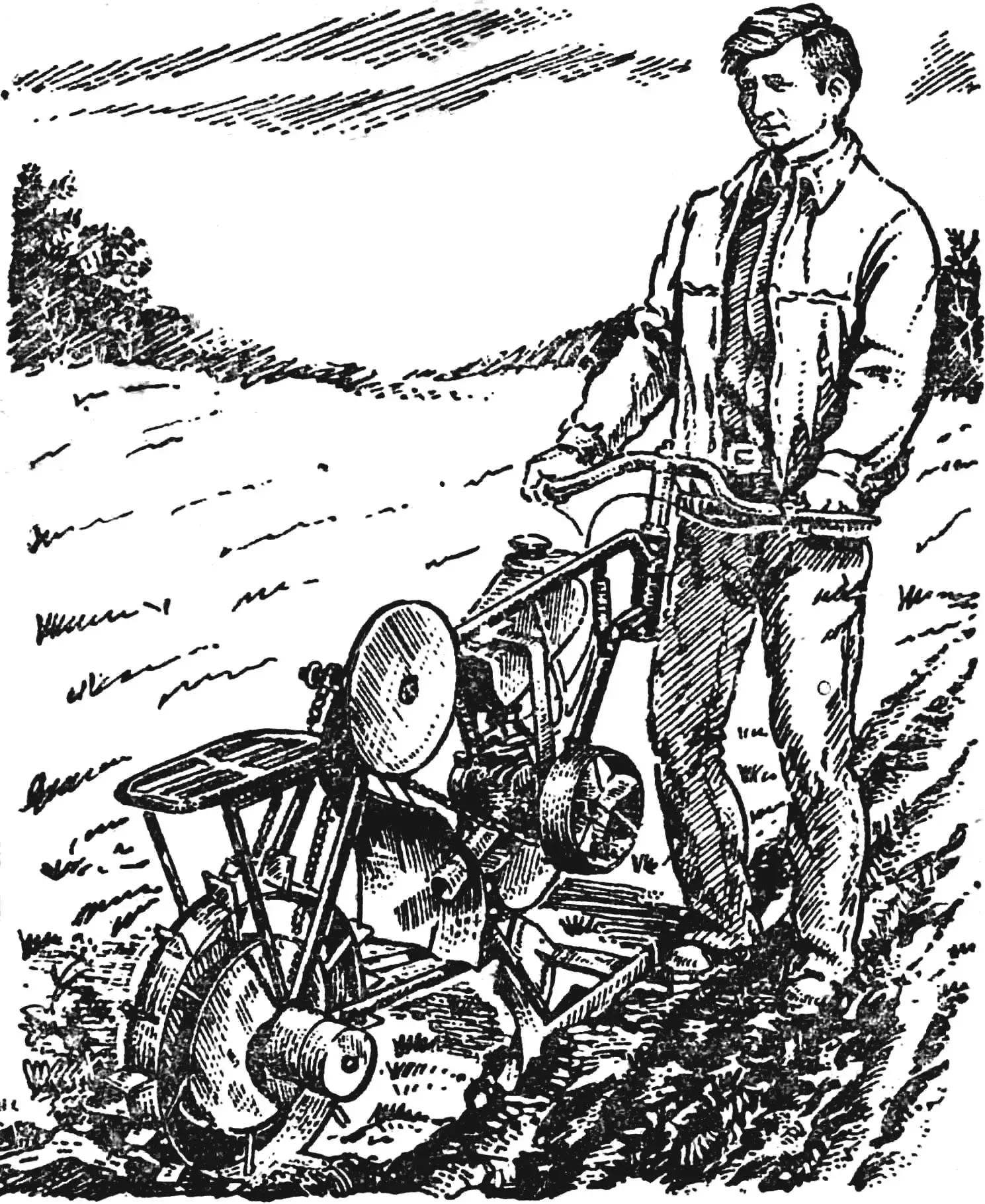
Is it not tempting to build a motorized plow whose construction has almost no welded joints! That is why the article “At the wheel of a veloplow” published in “M-K” No. 3, 1985—on how to build such a mechanism using the frame of a worn-out bicycle—drew a wide response.
However, many letters received by the editorial office asked for more detailed drawings and for information on engine modifications. Today the author of “At the wheel of a veloplow,” V. Zaets, answers these questions. At the same time we decided to introduce our readers to another appealingly simple motorized veloplow of a similar design, made by schoolchildren from the Novgorod region.
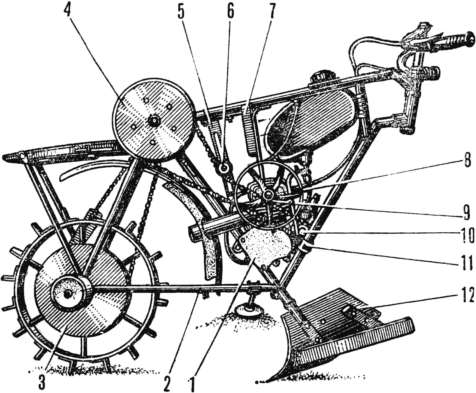
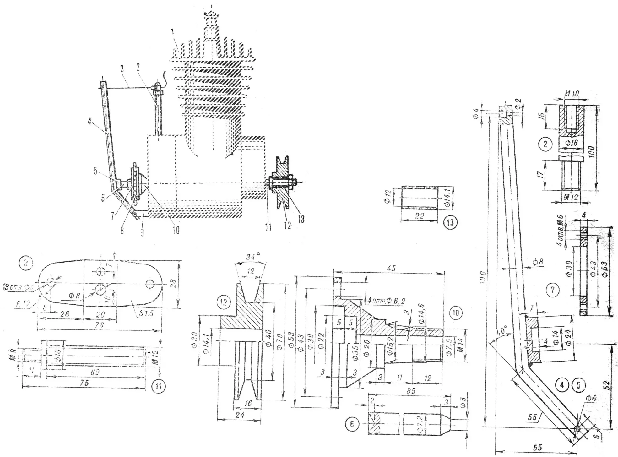
1 — D-6 engine, 2 — bicycle frame, 3, 4 — sprocket housings Z=48, 5 — idler sprocket bracket, 6 — idler sprocket Z=10, 7 — fan bracket, 8 — fan housing, 9 — fan, 10 — output sprocket Z=10, 11 — engine mounting clamp, 12 — working implement (plow).
Operating experience with the veloplow, which I already described in the magazine, revealed some shortcomings of my original design. For instance, starting the D-6 engine by towing was not feasible for one person because of the high gear ratio of the chain reducer. The engine, which had no forced cooling, overheated heavily under load. Because the driven sprocket Z = 48 was close to the wheel, the gap between them became clogged with soil, so the chain kept slipping. The handlebar was not very well positioned, and its width was insufficient. The extra weight on the veloplow’s luggage rack, needed to improve drive wheel grip, raised the center of gravity and made the machine harder to control. All of this led me to modernize my mechanical helper.
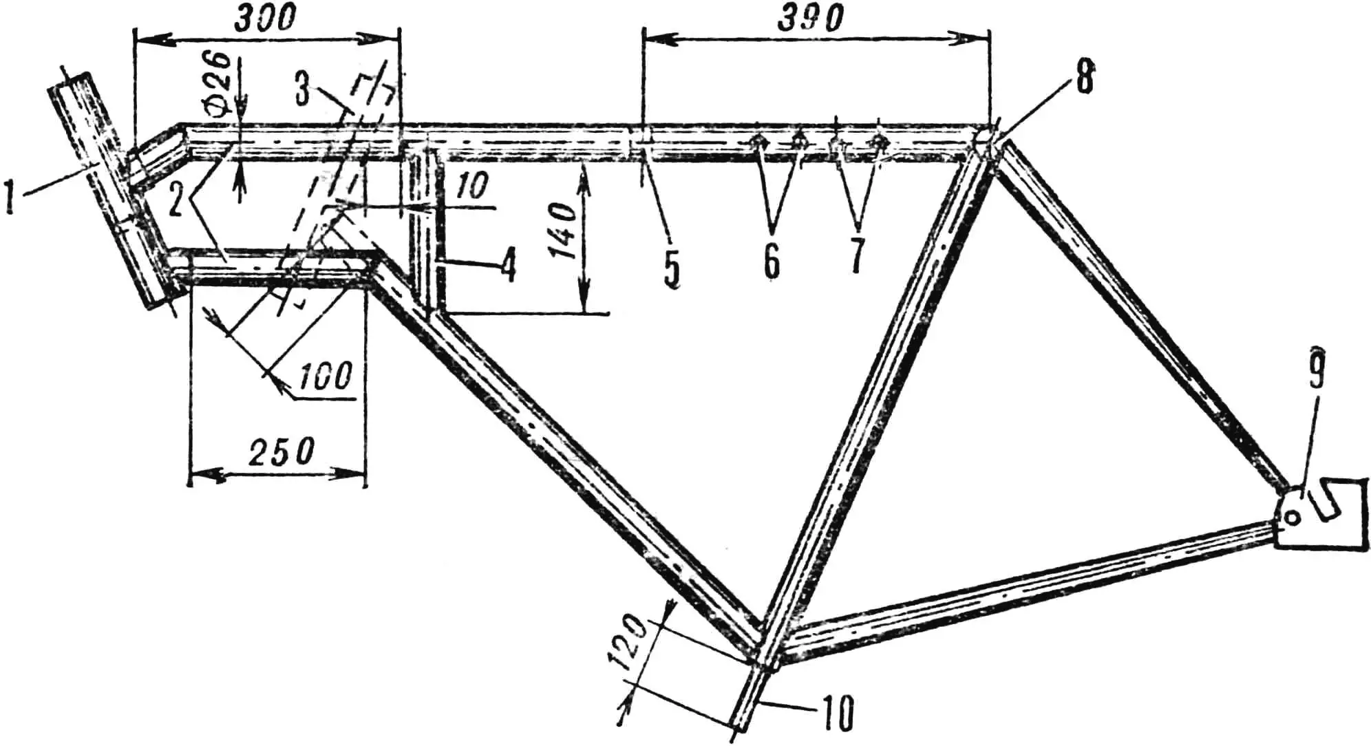
1 — handlebar stem, 2 — additional longitudinal tubes, 3 — original handlebar stem position, 4 — additional vertical tube, 5 — fan reaction thrust hole, 6 — fan bracket mounting holes, 7 — idler sprocket bracket mounting holes, 8 — intermediate shaft hub (bottom bracket), 9 — drive wheel mounting bracket, 10 — frame bracket.
First I improved the frame—lengthened it by 300 mm and welded the cut-off steering stem at a steeper angle. I increased the handlebar width by welding in a 250 mm insert. To improve drive wheel grip I made a new rim 100 mm wide, which required increasing the spacing between the rear fork blades.
To the latter on the right side of the frame I attached a bicycle footrest—now the veloplow does not tip over when stopped.
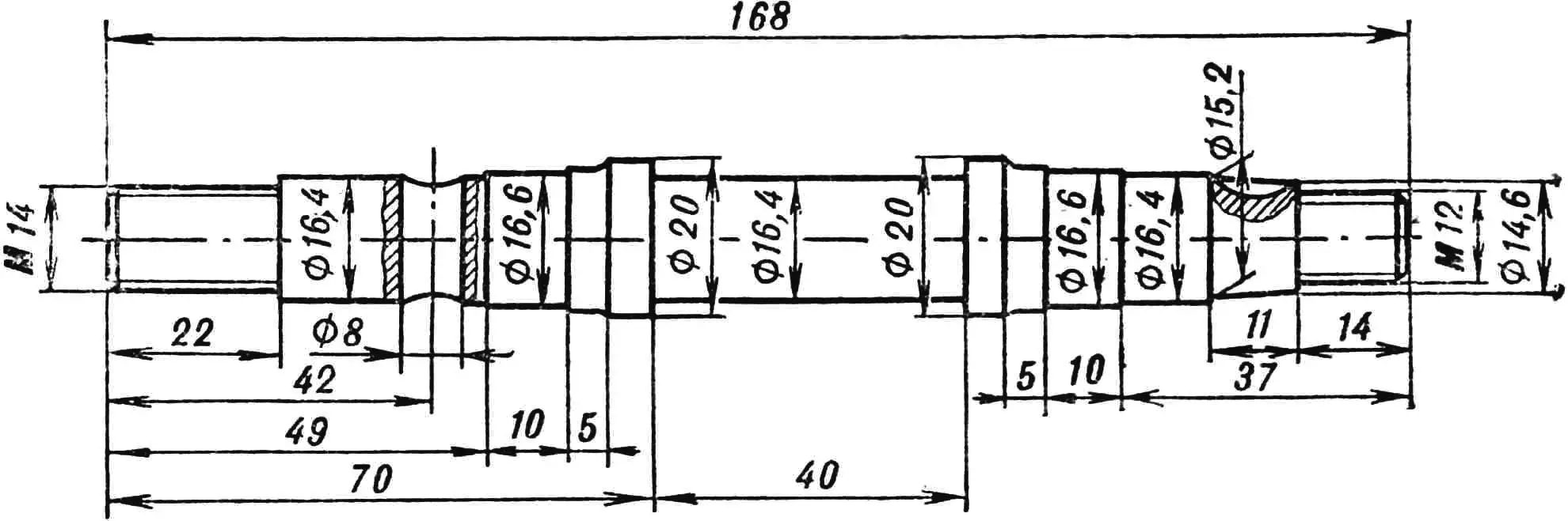
The machine’s transmission is a two-stage chain drive. The intermediate unit is a bottom bracket consisting of a shaft and two sprockets: Z = 48 from the bicycle and Z = 10 from the D-6 engine. I had to turn the shaft on a lathe, but all other bracket parts, including bearings, are standard bicycle components. I cut off the crank from the Z = 48 sprocket, leaving only the stub with the hole for wedge mounting. On both sides of the sprocket I fitted discs Ø 230 mm cut from 1 mm sheet metal to prevent chain derailment, and tightened the sprocket shaft with an M14 nut. The other bracket sprocket—Z = 10—I fixed with a key.
1 — D-6 engine, 2 — adjustment bolt extension, 3 — clutch cable, 4 — clutch release lever, 5 — release washer, 6 — push rod, 7 — flange washer, 8 — sprocket Z=10, 9 — release lever bracket, 10 — flange, 11 — pulley shaft, 12 — starter pulley, 13 — bushing.
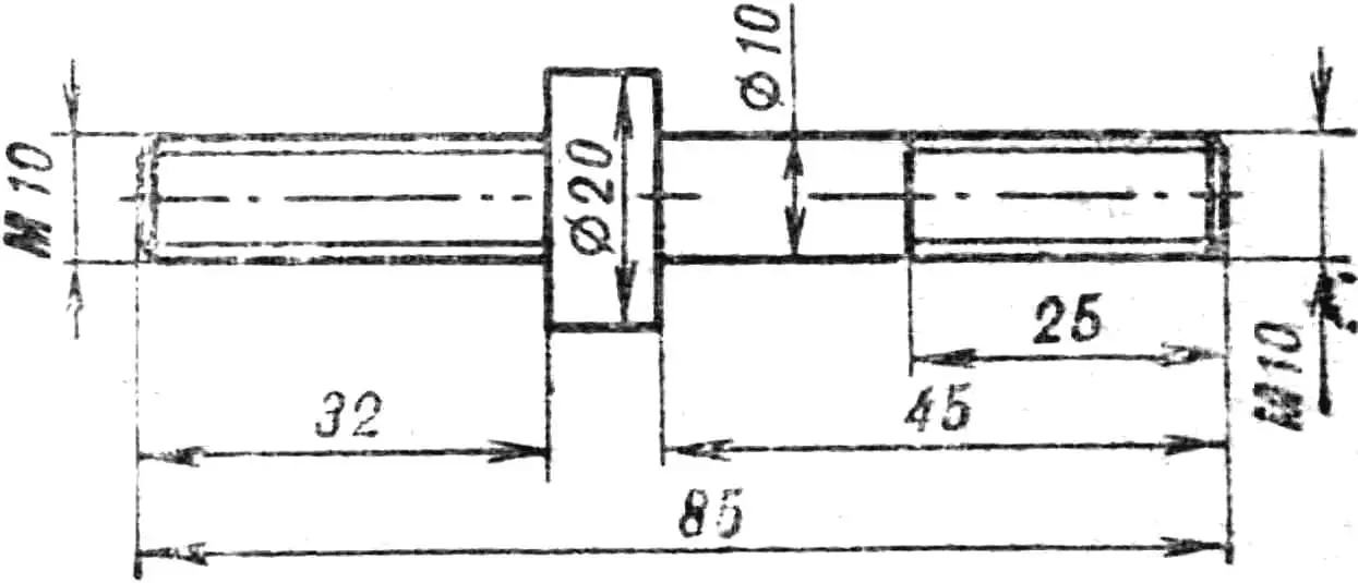
For the veloplow’s power unit I used the simple and reliable D-6 engine. Briefly on its modification. First I had to make a starting mechanism. I removed the reducer cover, unscrewed the M8 bolt and in its place installed a pulley shaft also turned on the lathe, using it to clamp the drive gear Z = 20. To prevent the shaft from loosening on its own I soldered it around the sprocket. I drilled a Ø 12.5 mm hole in the center of the reducer cover. The starter pulley itself can be turned from aluminum or taken ready-made—e.g. from the “Riga” washing machine motor.
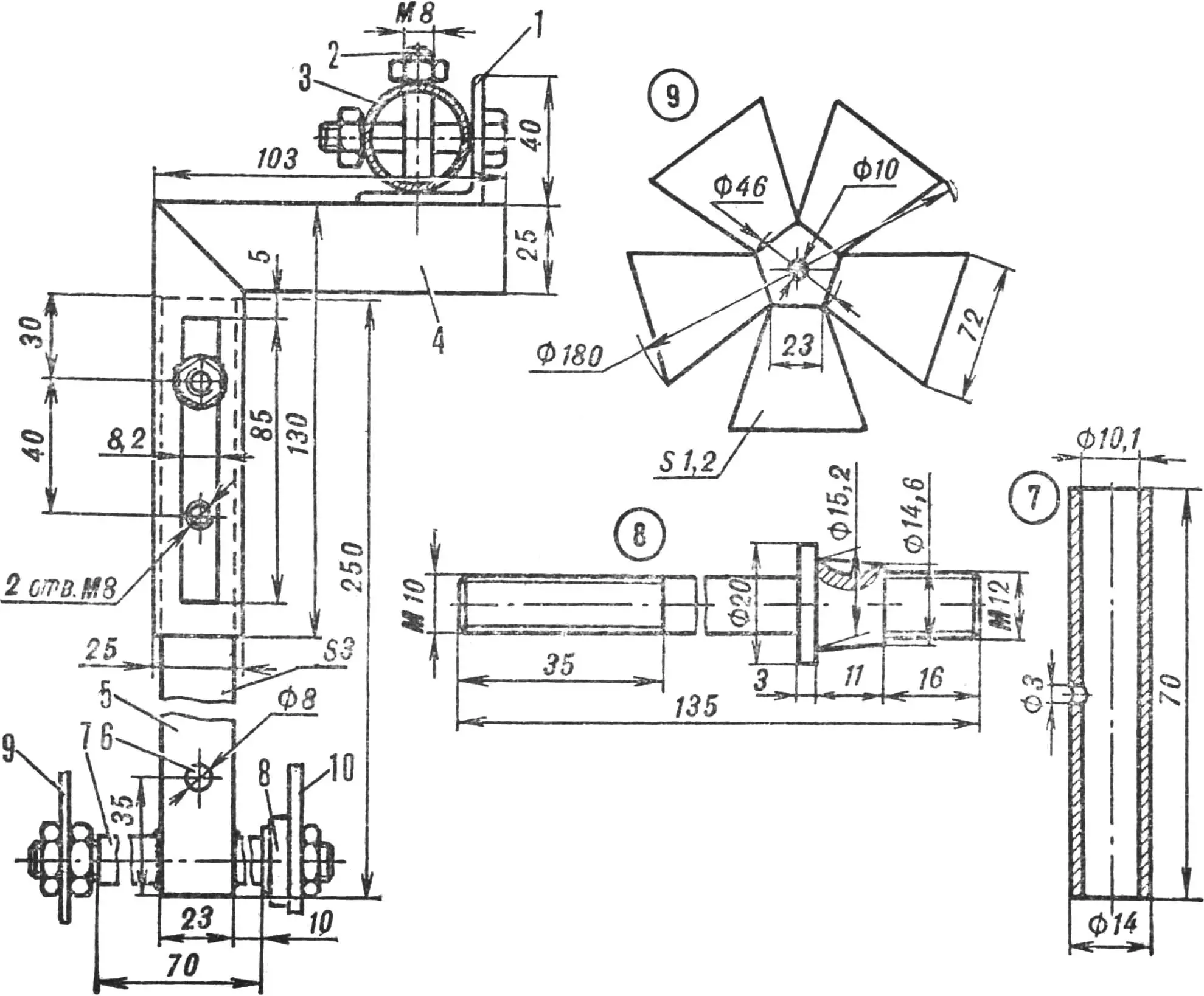
1 — 40×40 angle, 2 — M8 bolt, 3 — veloplow frame, 4 — movable suspension bracket, 5 — movable bar, 6 — reaction thrust hole, 7 — fan shaft bushing, 8 — fan shaft, 9 — fan, 10 — sprocket Z=10.
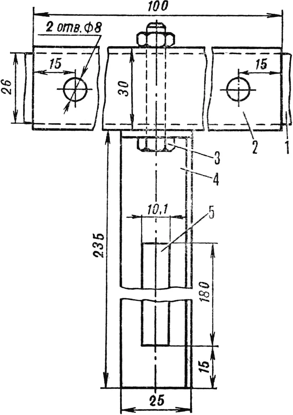
An equally important modification was moving the output sprocket Z = 10 outside the clutch cover. I placed the sprocket between a specially turned flange and washer (see Fig. 4). The sprocket is secured with a nut and locknut plus four M6 screws. The screw heads should be soldered or filled with thick paint so they do not loosen from vibration.
1 — frame tube, 2 — 30×30×3 angle, 3 — M8 bolt, 4 — 25×25×3 angle, 5 — slot for chain tension adjustment.
This change required modifying the clutch release. I had to extend the clutch release lever and drill a Ø 20 mm hole in the cover at the push rod location. In the clutch cover above the release lever shaft I drilled a Ø 10 mm hole and tapped M12 thread. Then I turned an extension bolt into which I screwed the clutch cable adjustment bolt from above. To the lower hole in the cover I attached the clutch release lever bracket. I made the lever from an 8 mm diameter, 215 mm long steel rod. I put a ball in the drive sprocket flange hole and inserted an 85 mm long push rod, then fastened the release lever to the bracket with an M4 bolt and fitted the clutch cable. The modified engine layout is shown in Figure 4.
In operation the veloplow travels at 4.1 km/h. Naturally the D-6 engine overheats under such load. So I had to build a forced cooling system. I cut the fan from 1.2 mm thick sheet metal, bent the blades at 30°, and drove it from the Z=10 sprocket, whose engagement with the chain is adjusted by a plate bracket (see Figure 5). The blades rotate inside a Ø 190 mm sheet metal housing.
«M-K» 2’87, V. ZAETS, Kharkiv
Recommend to read
 SEMI-AUTOMATIC WELDING
Sure: compact welding machine (ESPA), the merit of which is guaranteed by the protective electronics and the environment carbon dioxide, in any sector will not be superfluous,...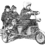 ON ASPHALT WITH A BOAT MOTOR
After reading the title, you might think: a motor is being repaired. Nothing of the sort. This patially "Surf" in excellent condition. But it is not set on the boat, and on the original...
