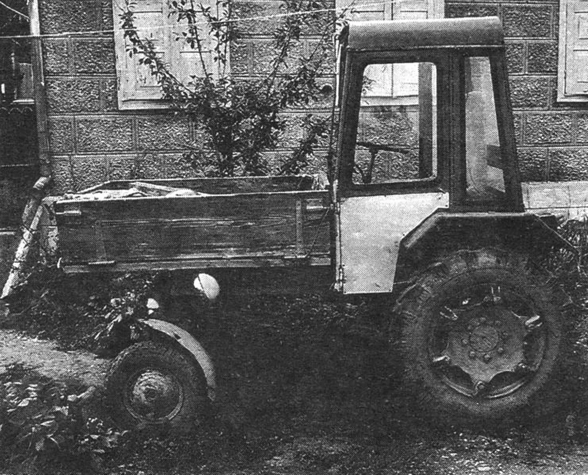
We continue the story of the machines and mechanisms built by V. A. SVERBL — an amateur designer from the village of Zelenchukskaya in the Karachay-Cherkess Republic. In the publications “Walk-behind tractor — nothing superfluous”, “A reliable helper for the walk-behind tractor” and “A compact car with the character of an all-terrain vehicle” (“Modelist-Konstruktor” Nos. 2, 3 and 4 for 1998), his “Elektronik” walk-behind tractor, cargo trailer and jeep-style car are described. This time the subject is the design of the “Shassik” mini-tractor.
V. A. Sverbl built the mini-tractor at the request of his older brother. The brother had started a major house renovation and hoped to use the “Elektronik” with a trailer to deliver building materials. However, Vasily Alekseyevich could not spare the walk-behind tractor for long — his own and the neighbors’ vegetable gardens would not wait — so he decided to “quickly” make something that could haul loads, turn around literally on a dime (his brother’s yard was not all that large), and at the same time till the garden. A tractor of the “self-propelled chassis” layout suited this role perfectly. Hence, incidentally, its name — “Shassik”.
The new vehicle was built, like everything Sverbl Jr. took on, very quickly. Literally a week later a blue-painted mini-tractor rolled up to the yard of Sverbl Sr.; as soon became clear, it could carry up to half a ton of cargo at up to 50 km/h and turn around on a pad with a radius of 3.5 m.
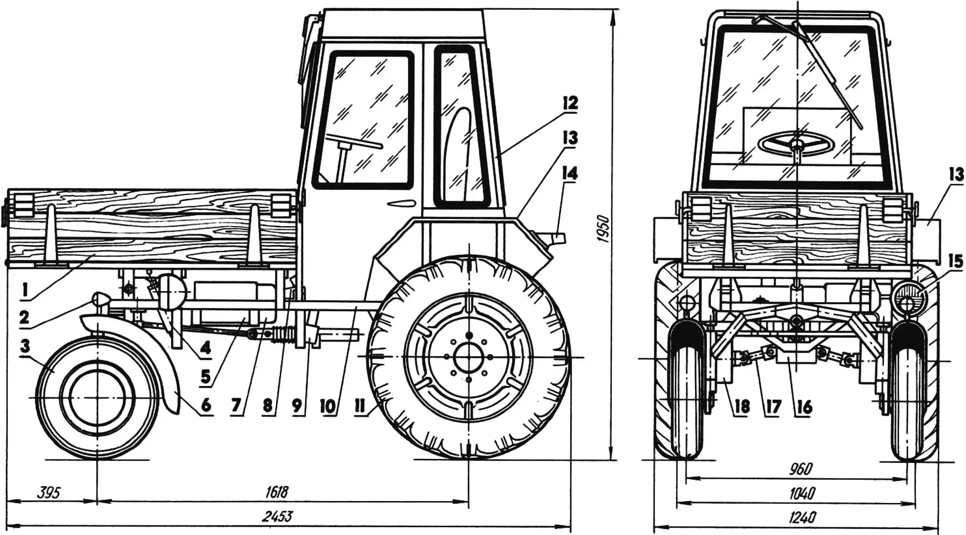
1 — cargo body; 2 — front turn signal (2 pcs.); 3 — front wheel (from an S3D motorized carriage); 4 — body-lift hydraulic cylinder (from farm machinery, shortened); 5 — battery; 6 — front fender; 7 — fuel tank; 8 — master brake cylinder (from S3D); 9 — steering gear (from S3D); 10 — frame; 11 — rear drive wheel (from a T-40 tractor); 12 — cab; 13 — rear fender; 14 — rear turn signal (from T-40, 2 pcs.); 15 — road headlight; 16 — final drive; 17 — propeller shaft; 18 — final-drive reduction gear (from T-40).
“Shassik” was assembled, as they say, from whatever was available. It uses a great deal of what fills the garages and sheds of self-respecting DIY builders. In this case the designer took the engine with gearbox, starter, generator, fuel tank (18 L capacity), steering gear and brake-system units from an S3D motorized carriage; the final drive from a “Muravey” cargo scooter; the propeller shafts from a GAZ-51 truck; on the front axle he fitted the rear wheels with hubs and brakes from the same motorized carriage, and on the rear drive axle — the front wheels with final-drive reduction gears from a T-40 tractor. The battery for the 12 V onboard electrical system came from a “Zhiguli”, the windshield-wiper motor and blade from a GAZ-69, and the remaining electrical equipment from other machines and mechanisms.
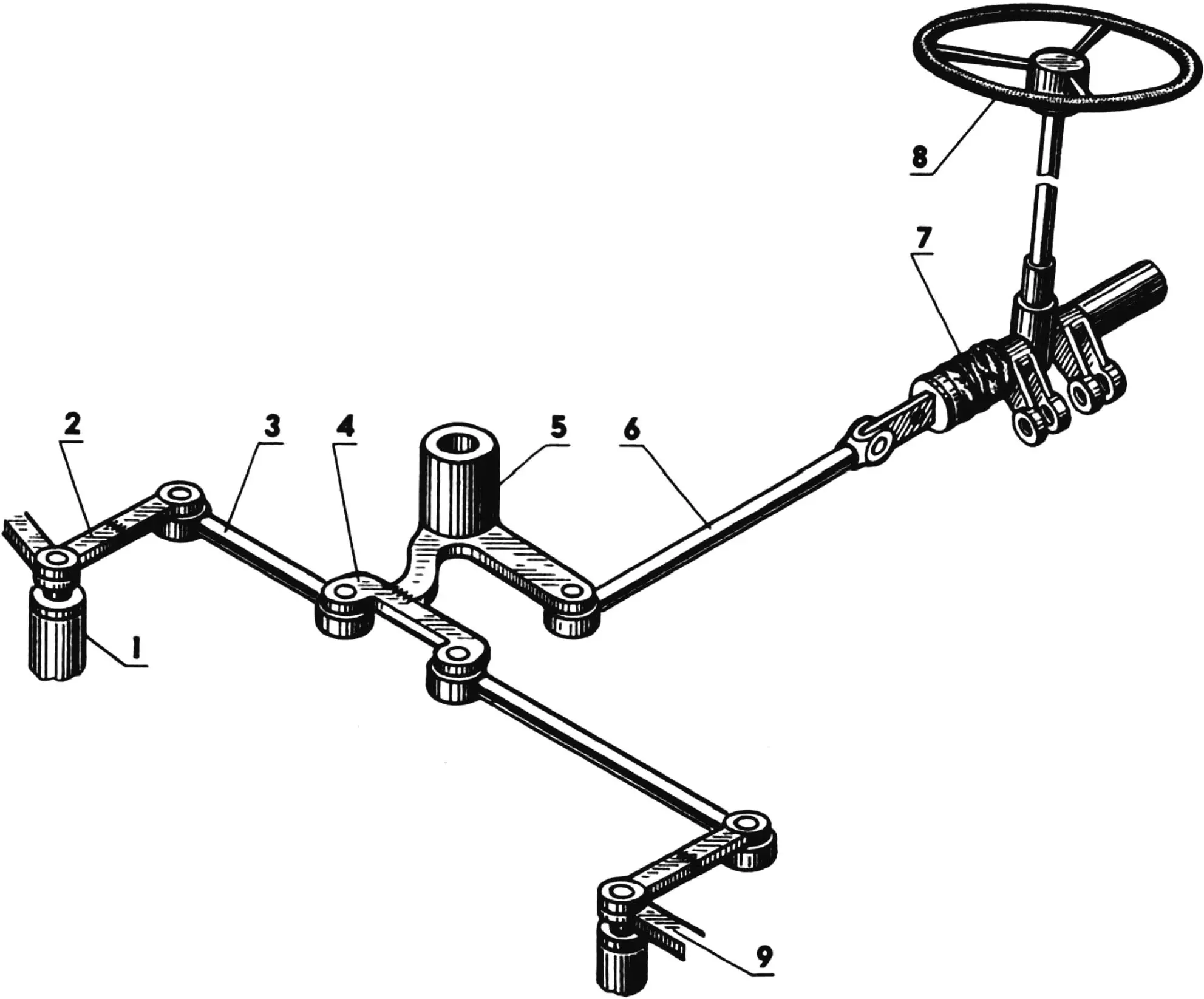
1 — front-axle kingpin bushing; 2 — pitman arm; 3, 6 — rods; 4 — rocker; 5 — steering-rocker pivot bushing; 7 — steering gear; 8 — steering wheel; 9 — fender mounting lug.
Using ready-made units and assemblies made it possible to reduce the number of homemade structural parts to a minimum and thereby substantially shorten the time needed to build the mini-tractor.
Here are those homemade parts.
FRAME. It is a simple truss welded mainly from angle stock of various sections. Despite the large number of parts, the frame is fairly easy to make. The truss design is shown in the drawing and therefore needs no detailed description. Just a word about the fact that the side-reduction-gear brackets have lugs for attaching a hitch bar for implements — a strong thick-walled pipe that can tow a plow, a harrow, or a drag.
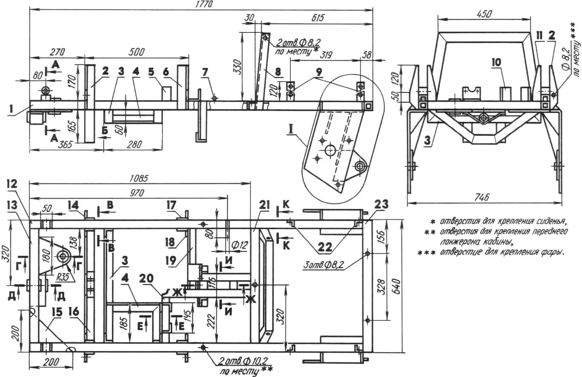
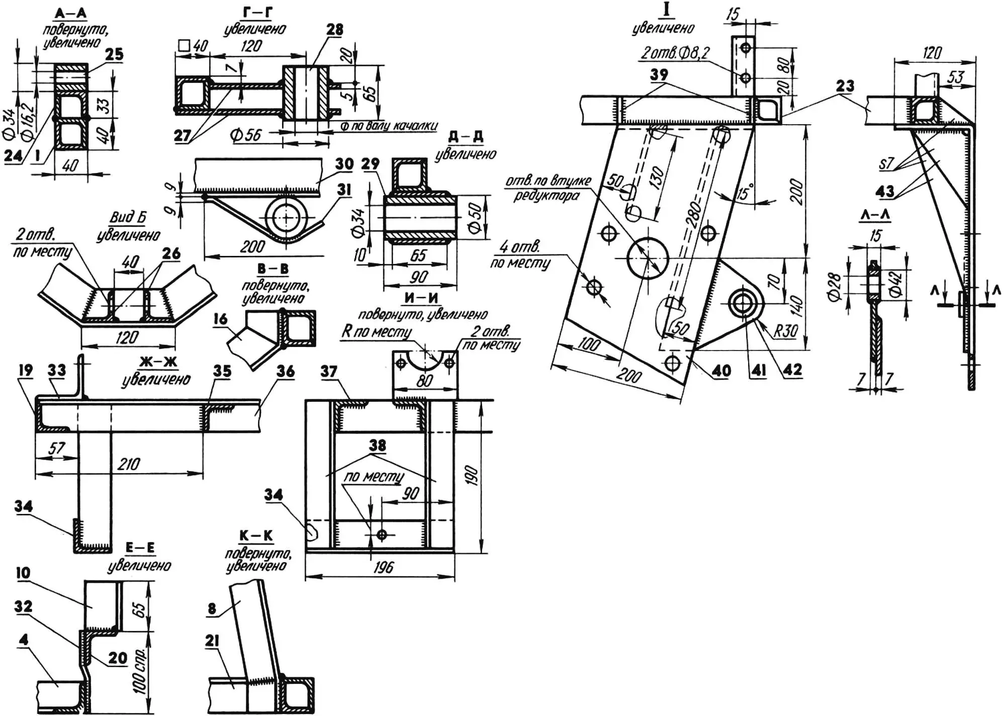
1, 12 — side members (angle 40x40x4); 2, 6, 11, 14, 17, 18 — cargo-body supports (angle 45x45x5); 3 — fuel-tank support (angle 36x36x4); 4 — battery support (angle 36x36x4); 5, 10 — oil-pump mounting brackets (angle 45x45x5); 7 — throttle-pedal shaft (rod Ø12); 8 — seat arch (angle 40x40x4); 9, 22 — rear-fender mounting brackets (angle 32x32x3); 13, 21, 23 — crossmembers (angle 40x40x4); 15 — gusset (steel sheet s5); 16 — hydraulic-cylinder support (angle 45x45x5); 19, 20 — side links (angle 40x40x4); 24 — extension (angle 40x40x4); 25 — body-pivot bushing; 26 — hydraulic-cylinder mounting lugs (angle 40x40x4); 27 — steering-rocker pivot cheeks (steel sheet s5); 28 — steering-rocker pivot bushing; 29 — front-axle suspension pivot bushing; 30, 31 — bushing holders (steel sheet s9); 32 — shackle (steel strip 40×5, 2 pcs.); 33 — master-cylinder mounting bracket (angle 60x60x3.5); 34 — steering-gear mounting crosspiece (angle 40x40x4); 35 — middle link (angle 36x36x4); 36, 37 — seats/rests (angle 40x40x4); 38 — overhangs (angle 36x36x4); 39, 43 — stiffeners (steel sheet s7); 40 — left side-reduction-gear bracket (steel sheet s7); 41 — implement-bar bushing; 42 — bar mounting lug.
CAB. The climate of Karachay-Cherkessia is difficult, and the weather in the foothills is unpredictable. Therefore the mini-tractor cab was designed so that one could work in it at any time of year — including winter, because warm air from the engine under the driver’s seat heats it well. The walls did not even need to be insulated.
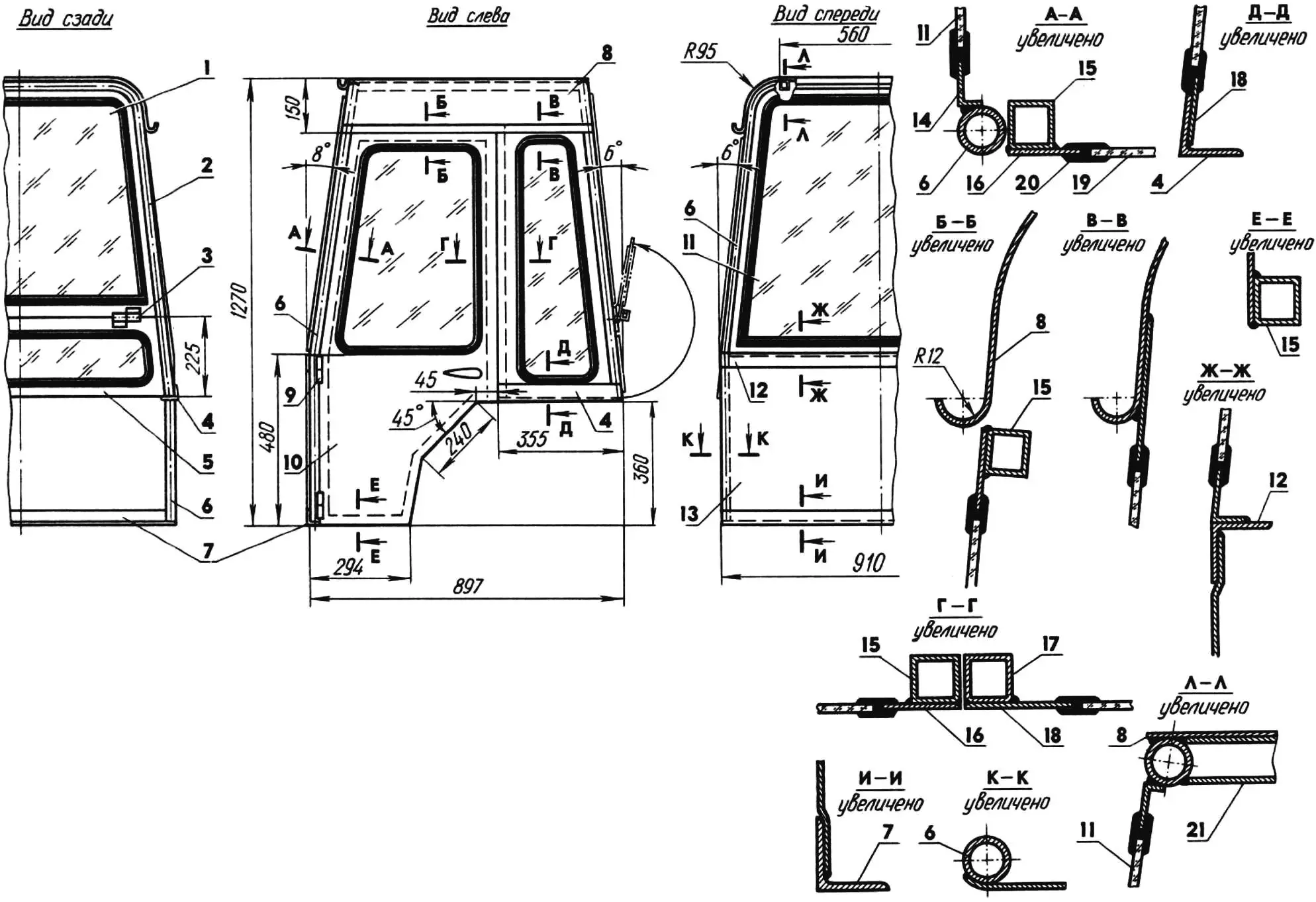
1, 11, 19 — glass panes (sheet s4); 2, 6 — arches (tube 27×3); 3 — transom hinge (2 pcs.); 4 — seat/rest (angle 36x36x4, 2 pcs.); 5 — transom; 7 — support beam (angle 40x40x4); 8 — roof (steel sheet s3); 9 — door hinge (2 pcs.); 10 — door (left side only); 12 — windowsill (angle 36x36x4); 13 — front wall (steel sheet s3; opening for the master cylinder not shown); 14, 18 — glass trim panels (steel sheet s3); 15 — door frame (tube 26x26x1.5); 16 — door skin (steel sheet s3); 17 — side pillar (tube 26x26x1.5, 2 pcs.); 20 — glass edging (special rubber profile); 21 — roof stringer (tube 26x26x1.5, 2 pcs.).
On a hot day the cab is easily ventilated; for this purpose it has a rear transom that opens upward.
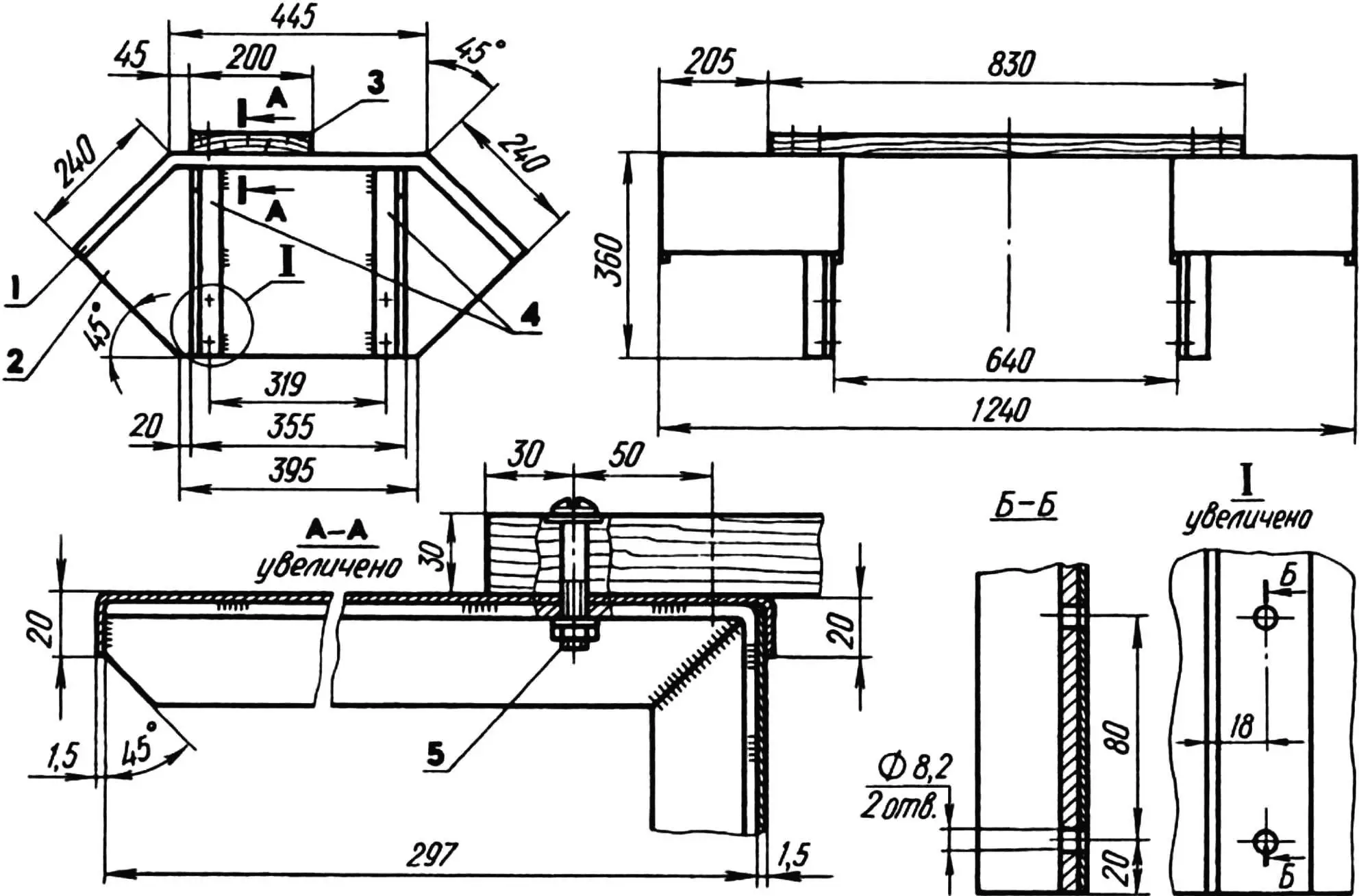
1 — fender (steel sheet s1.5); 2 — filler panel (steel sheet s1.5); 3 — seat-support crosspiece (board); 4 — bracket (angle 36x36x4); 5 — M8 bolt (4 pcs.).
The driver’s workstation is equipped with everything needed for full control of the mini-tractor: a steering wheel, clutch, throttle and brake pedals (its hydraulic actuator acts only on the front wheels), gearshift, reverse and parking-brake levers (its mechanical actuator also acts only on the front wheels), and an instrument cluster for monitoring the engine and onboard systems.
CARGO BODY. Its dimensions are modest, yet, as Vasily Alekseyevich put it, it holds “forty buckets and two more sacks of potatoes on top”.
The body is made of knot-free pine boards 30 mm thick, lined on the floor with steel sheet and reinforced on the sides with steel angles. The front and side boards are hinged, which makes loading and unloading easier. The body is still unloaded by hand for now, although provision is made for mechanical tipping with a power hydraulic drive.
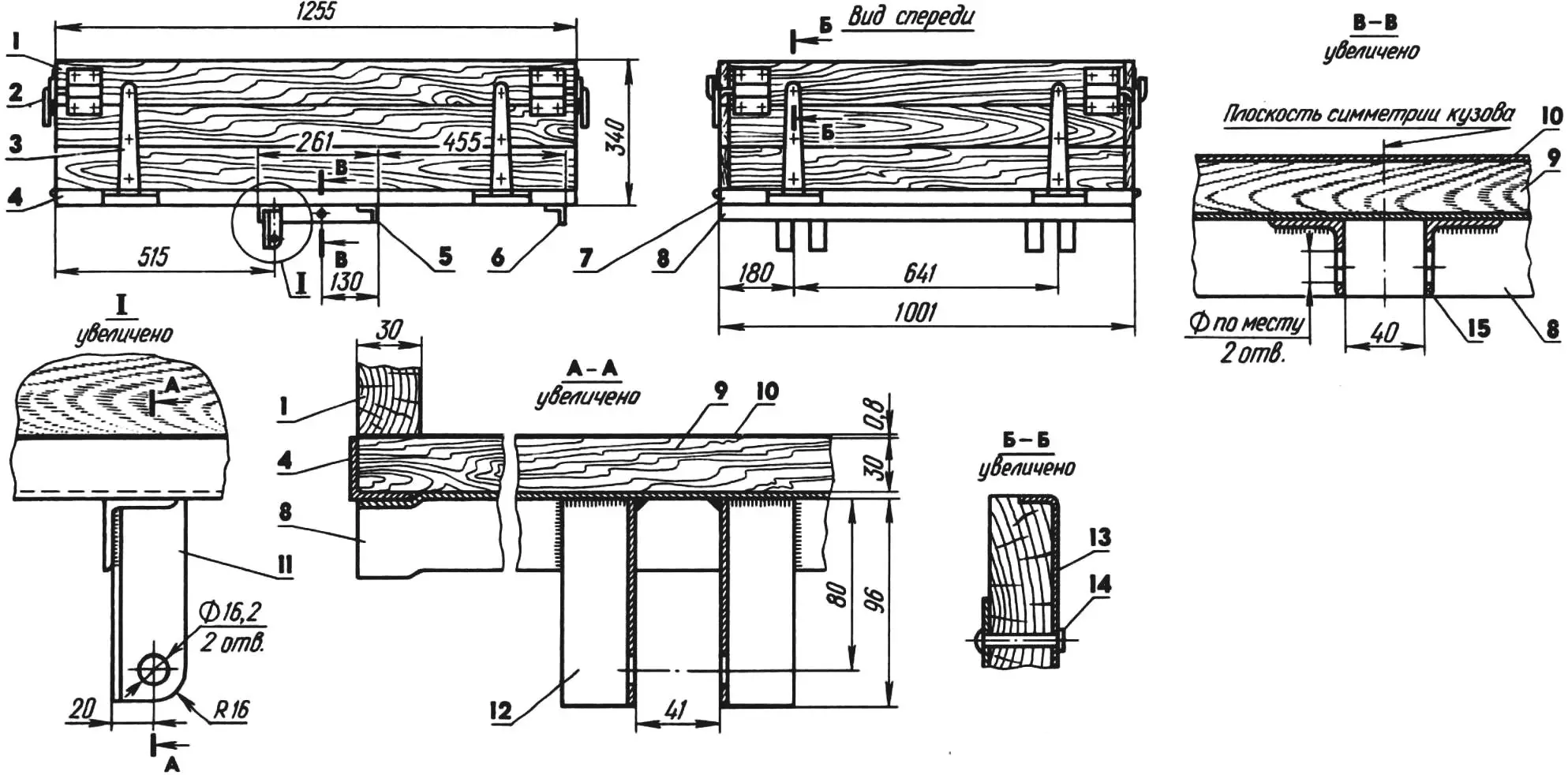
1 — left side board (board); 2 — side-board latch (4 pairs); 3 — side-board hinge (6 pcs.); 4, 7 — side-board edgings (angle 32x32x3); 5, 6, 8 — crossmembers (angle 36x36x3); 9 — floor (board); 10 — lining (steel sheet s0.8); 11, 12 — left-bracket uprights (angle 36x36x4); 13 — trim strip (steel strip 20×3); 14 — rivet (Ø 4, 24 pcs.); 15 — hydraulic-cylinder support (angle 36x36x4, 2 pcs.).
Space on the frame is even reserved for a hydraulic pump and a hydraulic cylinder: the former is located behind the battery, and the latter is pivot-mounted in the lugs of the matching support. Its rod bears against the geometric center of the floor, located behind the axis about which the body pivots when raised. This kinematics simplified the body design and eliminated the need to lock it against self-tipping. However, for lack of time Vasily Alekseyevich left the engine modification for driving the hydraulic system for later.
FRONT AXLE. It is a lever-type design with one degree of freedom. It is made of several lengths of thick-walled steel tube and is attached to the front of the frame by a sturdy pivot. The kingpin bushings are also made of steel tube and contain bronze plain bearings and kingpins, to the bottoms of which are welded hub brackets cut from the swing arms of an S3D motorized-carriage rear axle. Steering pitman arms and plate-type fender mounting lugs are bolted to the tops of the kingpins.
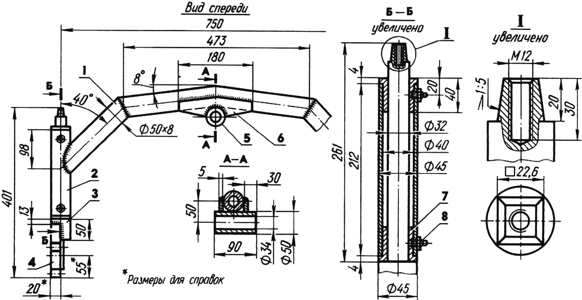
1 — beam (tube 50×8); 2 — kingpin bushing (tube 45×2.5); 3 — kingpin; 4 — hub bracket (from an S3D swing arm); 5 — hitch pivot bushing (tube 50×8); 6 — gusset (steel sheet s5, 2 pcs.); 7 — plain-bearing bushing (bronze, 2 pcs.); 8 — grease fitting (2 pcs.).
Here it is worth describing a small modification of the motorized carriage’s steering. An additional pivot assembly (the stator belongs to the frame, the rotor to the steering rocker) and the rocker itself were added to the stock set of parts. Owing to its rather complex shape, it introduces nonlinearity into the wheel-turning process, causing the inner wheel to deflect through a larger angle, which improves the mini-tractor’s maneuverability.
MUFFLER. It is assembled from lengths of pipe of various diameters. The inlet stubs are stock ones from the motorized carriage. On the mini-tractor the muffler is attached by two stock bracket clamps to the engine mount and connected to its exhaust pipes.
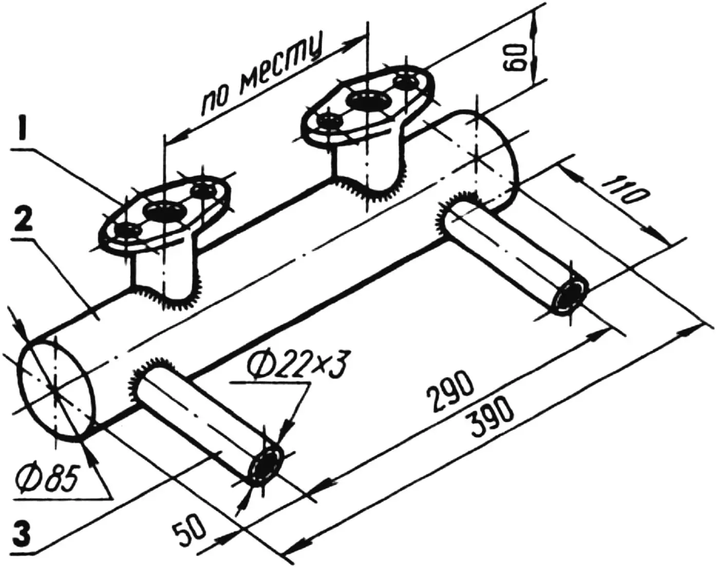
1 — inlet stub; 2 — resonator (tube 85×2.5); 3 — outlet stub (tube 22×3).
A few words about the “Shassik” transmission. As already noted, the designer took the final drive from a “Muravey” cargo scooter and mounted it in the stock engine-mount brackets. He then connected the outer yokes of the flexible drive joints to the forks of the rear-wheel final-drive reduction gears with half-axles — shortened GAZ-51 propeller shafts.

It would be wrong to claim that “Shassik” has no shortcomings. Like any homemade machine, it is far from ideal. Its virtue lies elsewhere. It is a clear example of a creative approach to reality. From seemingly scrap materials and worn-out parts, a rural designer built a mini-tractor that helps him solve many household problems. Such an attitude deserves both respect and imitation.
“Modelist-Konstruktor” No. 5’98, A. TIMCHENKO
Recommend to read
 “WATER BEETLES” IN THE SNOW
Paul A. Deryabkin, snowmobile enthusiast equipment Ivanova from the city, have created more than one snowmobile. His first design, snowmobile-amphibian (photo). successfully tested six... CANDLE holder
MATERIAL: heavy-gauge wire or metal rod with a diameter of 6 mm, copper thin wire, copper or brass sheet thickness of 3 mm. TOOLS: tin snips, hacksaw, file, drill and a drill bit Ø...
