Owners of private houses or dachas often face the need to prepare concrete solutions. Mixing water, gravel, and cement in a certain proportion is not difficult, but very labor-intensive, requiring considerable time and physical effort. And if it is necessary to perform large volumes, the process of preparing concrete or masonry mortar turns into hard labor.
The concrete mixer, which will be described below, is distinguished not only by its simplicity but also by its ease of use.
Using it is not tiring, mixing the components lasts only 10 — 15 seconds, not counting the moment of loading the concrete mixer. And the mood improves from quickly completing such necessary work. Moreover, it is done with quality, as the mixture is thoroughly mixed and becomes homogeneous, which is very important for the manufacture of concrete and reinforced concrete structures.
A significant advantage over many other variants of similar devices is that its manufacture did not require sophisticated and expensive drive mechanisms (electric motor, gearbox, pulleys, belts), since the drive is manual, with a rotation lever.
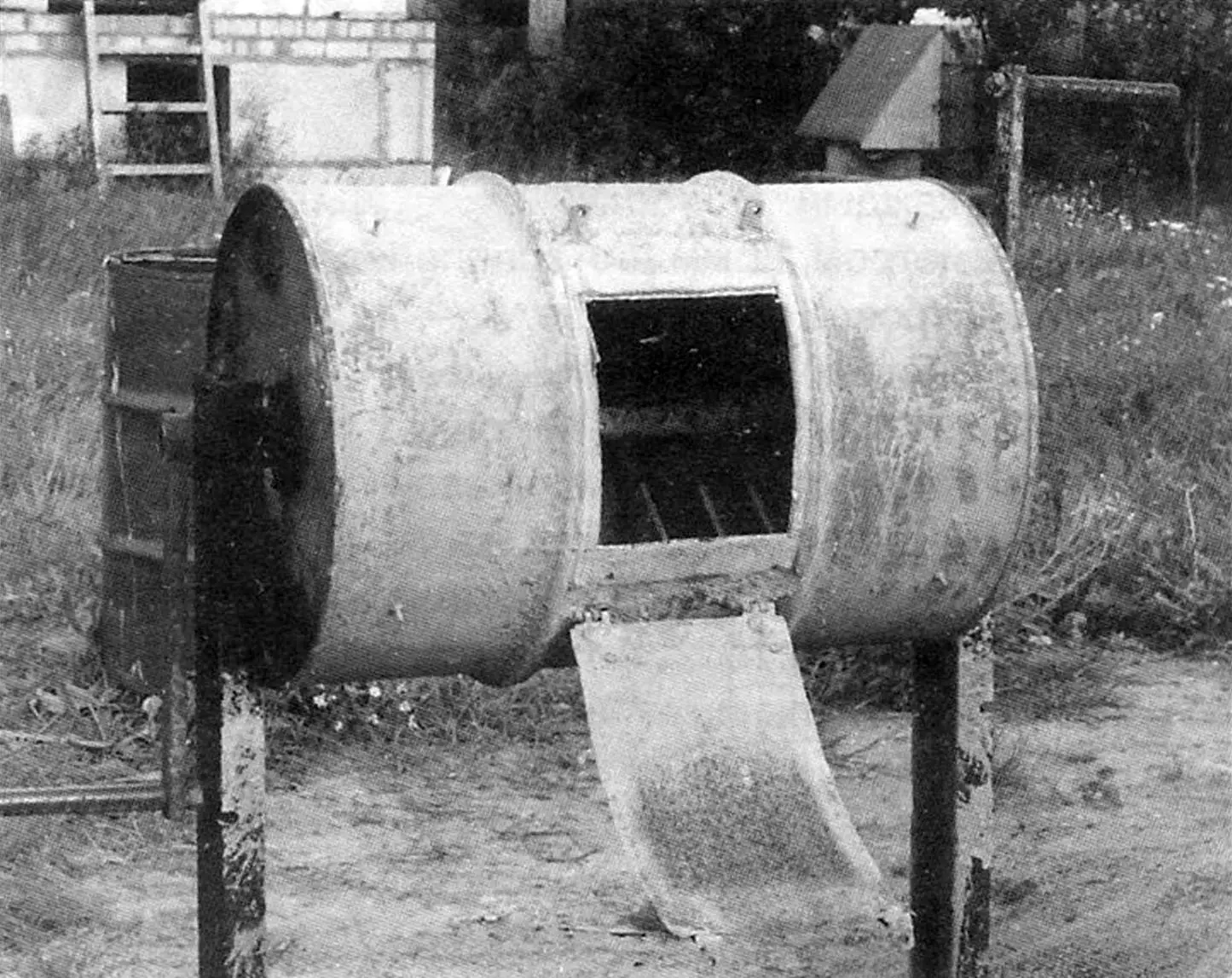
The concrete mixer is made from an ordinary 200-liter barrel, horizontally mounted on a working shaft installed on two supports in rolling bearings; loading-unloading is through a rectangular opening in the shell. Many variants of concrete mixers based on standard barrels have been described. Each of them has its own “peculiarity”. Here, the “highlight” is the combs located inside the drum, ensuring accelerated mixing and improved quality of the concrete mixture.
Well, now a few practical tips for making a concrete mixer for those who have decided to repeat our experience.
First of all, you should prepare the necessary materials: a 200-liter barrel, channel No. 10 (or weld 50×50 angles along the edge), a 40 mm diameter round bar, rolling bearings 208 (2 pcs.) and other items, in accordance with the list of positions in the drawing.
We start manufacturing by processing the barrel. In the center of the bottom and lid, we drill holes with a diameter of 40.5 — 41 mm for the shaft and corresponding holes for flange mounting bolts, with which the drum is rigidly connected to the shaft. For loading concrete mixture components, we cut a rectangular opening 240×300 mm in the middle of the barrel wall and glue strips of soft rubber 5 — 8 mm thick along the outer contour for sealing.
We make a lid that closes the drum during mixing and attach it hingedly using card hinges, and to fix it in the closed position, we install two brackets (40×40 angles) with holes 8 — 9 mm in diameter for tie bolts on the barrel and lid (of course, it would be better to weld them, but bolted fastening can also be used). To fix the lid, special latches, the so-called “frogs”, are quite suitable instead of angles and tie bolts.
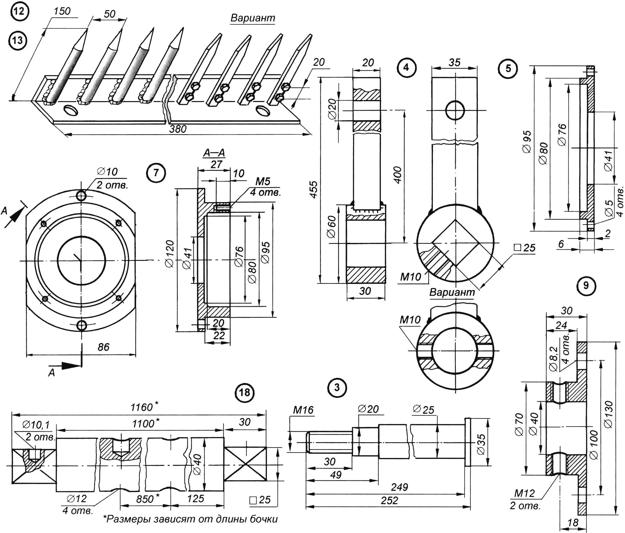
Inside the barrel, along its generatrices at 90° intervals, we install combs made of 36×36 mm angle (or slightly larger) with welded steel pins 10 — 12 mm in diameter and 150 mm long at 50 mm intervals (pins can also be made from strips, replacing welding with bolted fastening). The length of each comb is 760 mm (for convenience of installation inside the drum, it is better to make it from two halves).
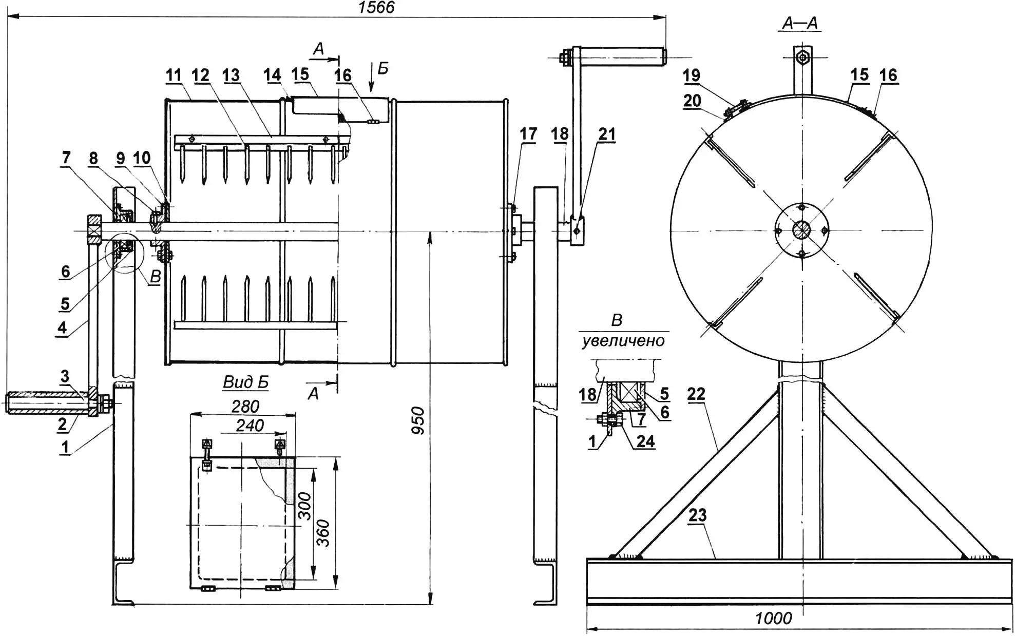
1 — stand (channel No. 8, No. 10, angle No. 5); 2 — handle attachment (pipe 40×5, L245, 2 pcs.); 3 — handle axis (round Ø35, 2 pcs.); 4 — lever (strip 20×35, round Ø60, 2 pcs.); 5 — bearing housing cover (2 pcs.); 6 — bearing 208 (2 pcs.); 7 — bearing housing (2 pcs.); 8 — flange stop (bolt M12, 4 pcs.); 9 — working container flange (2 pcs.); 10 — reinforcing washer (2 pcs.); 11 — working container (200 l barrel); 12 — comb pin (strip 4×10 or rod Ø12, 64 pcs.); 13 — comb base (angle 36×36, L380, 8 pcs.); 14 — opening seal (rubber); 15 — lid (sheet s1 — 1.5); 16 — card hinge (2 pcs.); 17 — flange fastening (bolt M8, 8 pcs.); 18 — shaft (round Ø40); 19 — lid tie (bolt M8, 2 pcs.); 20 — tie bracket (angle 40×40, 2 pcs.); 21 — handle stop (bolt M10, 2 pcs.); 22 — spacer (channel No. 8, No. 10, angle No. 5, strip); 23 — shoe (channel No. 8, No. 10); 24 — bearing housing fastening (bolt M10, 4 pcs.)
The next stage is the manufacture of the manual drive mechanism, which consists of a shaft rigidly connected to the drum and rotation levers mounted on the ends of the shaft.
The blank for the shaft is made from a round profile with a diameter of 40 — 45 mm, from ordinary carbon steel. It is well machinable, so some milling work can be replaced with locksmith work, for which a file with a coarse notch will be required. With its help, we form a square on the ends of the shaft for installing the rotation lever flanges. In one of the faces, we drill a shallow hole with a diameter of at least 10 mm and, accordingly, cut a through threaded hole M10 in the lever flange for a stop bolt. In addition, on the shaft in two places, we drill two blind diametrically located holes with a diameter of 12 — 12.2 mm: for the drum flange stop bolts.
When making flanges, you cannot do without lathe work, but you can try to find something suitable at scrap metal dumps. In this case, only some refinement of your finds will be required. If the inner hole is large, it is not difficult to reduce it using a transition bushing. If it is small — it is necessary to bore it. All this will reduce the cost of making the concrete mixer.
After refining the shaft and flanges, we begin assembly: we pass the shaft through the axial holes of the barrel while simultaneously mounting flanges on the outside and reinforcing washers on the inside of the drum. The washers are necessary to prevent ruptures of the drum walls, as barrels are made of very thin sheet steel. Through four holes drilled in the flanges and ends of the drum, we pass M8 bolts and tighten them with nuts with spring washers.
After the working organ is assembled, it remains to place it in the stands (it is better, of course, to make a frame, but this is extra material and time costs). For stability and rigidity, we weld a shoe (channel No. 8 or No. 10, 1000 mm long) and spacers from the same channel or from angles, or from strip steel 8 — 10 mm thick to the stands. If there is no welding, then the stands, shoes, and spacers can be connected using overlays and bolts. In the upper part of the stands, coaxially with the hole for the shaft, we fasten the bearing units with M10 screws.
The drawing shows the housing for ball bearing 208. Others can be installed — the main thing is that the shaft diameter is at least 30 mm. And one more requirement: the bearing housing must fit tightly to the inner wall of the stand — to ensure the rigidity of the structure. Therefore, if the outer diameter of the housing is greater than the distance between the channel flanges, then using a hacksaw, grinding wheel, or, if possible, on a milling machine, two flats should be removed from the side surfaces of the housing to the required size. To protect the bearings from moisture and dirt, the housing is closed with a cover.
A simpler (but less effective) variant of the bearing unit is a bronze bushing. To reduce friction in the “shaft — bushing” pair, it is advisable to drill a hole in the middle of the bronze bushing wall with an exit to the inner cavity, place felt strips in it, and fill it with machine oil. During operation, it is necessary to constantly add oil. To prevent water from entering the filling hole during rain, a screw must be screwed into it.
It remains to make the levers and handles for rotating the drum, again based on the available material. These parts are shown in the drawing. Another tip: to avoid calluses on your hands, it is necessary to install bushings cut from pipes with a gap on the handle axes, pre-lubricated with any lubricant, ensuring their free rotation. The length of the bushing should be such that it can be grasped with both hands.
After manufacturing all units and parts, we perform final assembly: we install the drum with the shaft in the bearing units in the stands, and mount the drum rotation levers on the ends of the shaft.
Then we dig two pits in the ground for the stands with shoes to a depth that should ensure convenient work taking into account your height. If unloading the ready solution is supposed to be done into a cart, then the height of the concrete mixer installation should be such that the cart can freely fit under the barrel hatch.
The technology for preparing the solution is very simple: we load sand with gravel, cement into the concrete mixer alternately, pour water (all this in the appropriate proportion), rotate the drum (approximately 10 — 15 revolutions) — and the solution is ready.
When performing large volumes of concrete work, you have to use the concrete mixer for a long time, with inevitable sticking of the solution in the gaps, at the corners of the comb connection with the drum body, as well as at its ends. Usually, a crowbar is used to knock off the sticking. This process is labor-intensive and extremely inconvenient to perform: after all, you need to get to the most secluded corners of the concrete mixer, otherwise the cleaning will be ineffective. But all this can be avoided if you use small cobblestones 30 to 80 mm in size in the amount of 1.5 — 2 buckets. We pour them into the concrete mixer, pour a bucket of water, and rotate the drum: 20 — 30 revolutions in one direction and the same in the other. Then we unload the contents of the concrete mixer into a vat or cart with sides (it is advisable not to delay this process, as particles of the solution settle on the drum walls again).
For the owner of such a concrete mixer, the work of preparing the solution will not require large time costs and will no longer be heavy.
«Modelist-Konstruktor» No. 2’2006, V. PATSINO, Borisov, Belarus
Recommend to read
 ITS ELEMENTS – LAND AND WATER
Moscow musician D. T. KUDRYAKOV among Amateur designers known as the author of a unique car is amphibious "Triton" — one of a kind vehicle that is registered simultaneously in two state... FUEL TANK — CO2
Whatever you say, but the popularity of a particular model often depends not on its flight data and... flight readiness. That is why many modelers prefer to equip their technique is...
