
When repairing and testing the electrical equipment of motoblocks not fitted with a battery, as well as Voskhod-3M motorcycles and mopeds, you have to start the engine each time to power the electrical system. It is troublesome and wastes fuel. Yet there is, in my opinion, a good solution: use the household mains as the energy source. All you need is a modified power supply unit from a children’s film projector.
Indeed, transformer T1 in a basic film projector can deliver up to 4 A into the load at 12 V on the secondary winding. All that remains is to convert alternating current into direct current and feed it through a probe and an electrical connector into the motoblock’s onboard network.
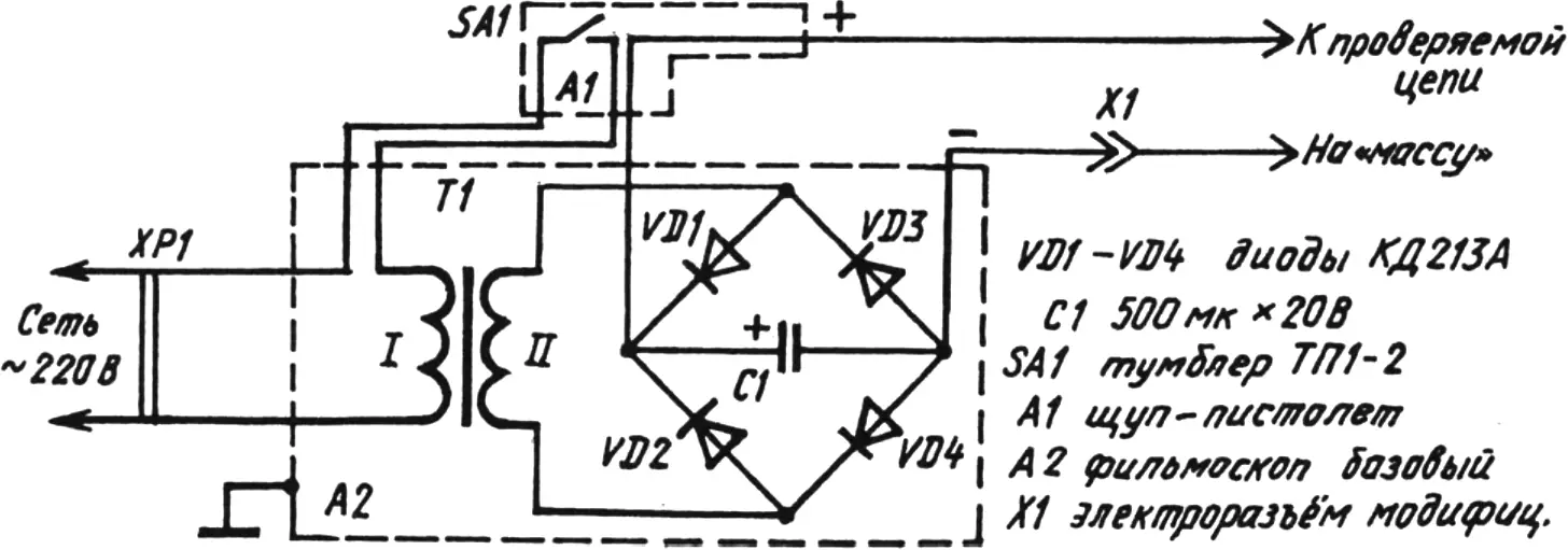
The first task can be handled by a rectifier built as a diode bridge VD1—VD4 with a high-capacitance capacitor C1 that smooths output voltage ripple. The second is solved with an improved toy pistol and a large colored eraser of the “Architect” type, with a connecting electrical terminal block cut into it.
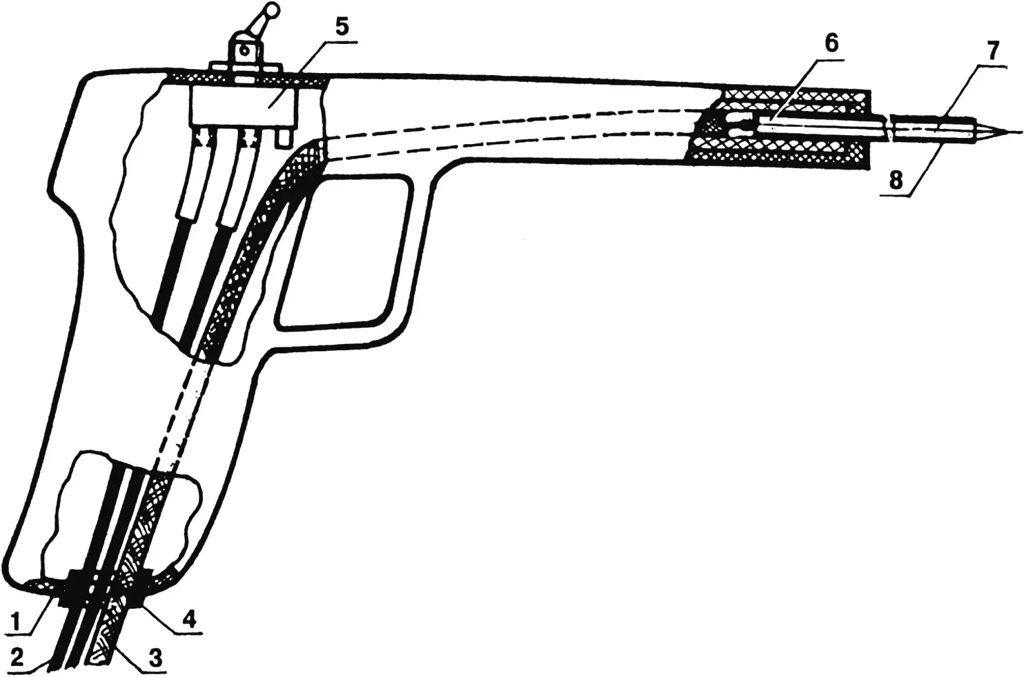
1 — housing (toy pistol); 2 — mains cord; 3 — power supply wire, positive; 4 — rubber bushing; 5 — switch TP1-2; 6 — foam seal; 7 — probe (pointed copper rod); 8 — vinyl insulation.
All of this is connected to the household mains with an ordinary plug XP1. Then the 220 V AC applied to the primary winding of T1 is transformed into 12 V, which after rectification and smoothing can be used to test the motoblock’s onboard electrical equipment: lighting devices, audible and visual signaling. The negative wire (usually black or blue) is connected directly to ground. The positive wire (as a rule, in red or orange insulation) is connected with the probe to the circuit being tested.
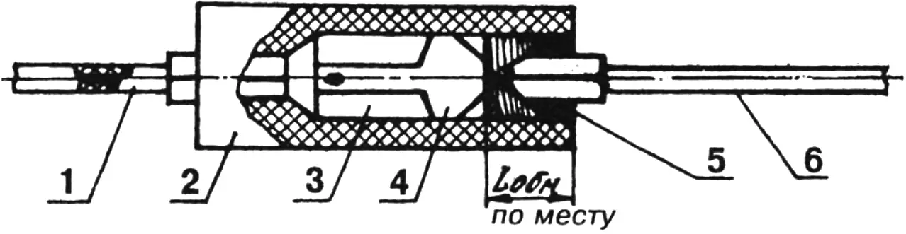
1 — input wire; 2 — elastic moisture-proof sleeve (office eraser of the “Architect” type); 3 — socket contact; 4 — pin contact; 5 — sealing wrap (rubber or polyethylene micro-cord); 6 — output wire.
This color coding should also be followed when using an “Architect” office eraser as a moisture-proof and substantially sealing electrical contact sleeve. Especially if the standard electrical connector has already worn out considerably.
One more important note. To avoid strong inductive current surges when “ringing out” electrical circuits, temporarily disconnect the CDI unit, ignition coil, and generator from the electrical system.
“Modelist-Konstruktor” No. 8’2000, D. YAKOVLEV
Recommend to read
 Sister stoves
Needless to say, it is pleasant to warm yourself on a damp or cold day by the home hearth (whether a Dutch stove or a European fireplace), and to admire it as well, if it is skillfully... TO CHANGE THE BLADE — NO PROBLEM
There are many devices DPJ pinching the blade of the jigsaw. Here is another, developed by I. Radchenko from the village of tal'menka of Altai Krai. In otpetie from the existing is a...
