In different regions of our country, the soil is cultivated in different ways. Soil and climate conditions naturally leave their mark on the designs of small-scale mechanization tools developed by owners of household plots. Some build micro-tractors and motor blocks designed for use with a plow; others build motor tillers.
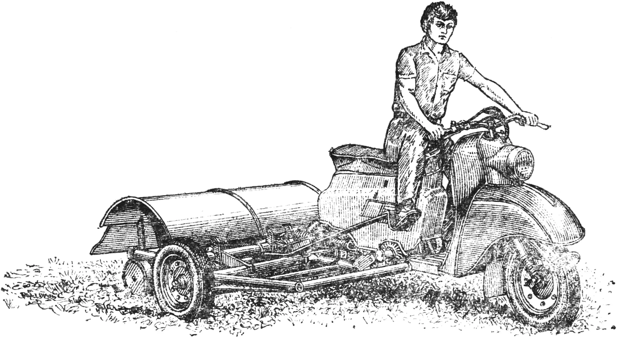
Our reader from Sverdlovsk Oblast, A. Gordin, offers a version using a set of cutters mounted on a homemade side trailer for the Tula-200 moped. The advantages of such a working tool are that it has a large working width and loosens the soil well.
My till implement, it seems to me, is attractive in that the moped does not have to undergo major modification. All you need to do is remove the rear wheel and mount it on the side trailer shaft. And slightly lengthen the drive chain, because the wheel moves back from the fork, and the rear cross tube of the trailer is attached to the fork. The front cross tube is inserted into the Tula frame in front of the engine and is hinged to it.
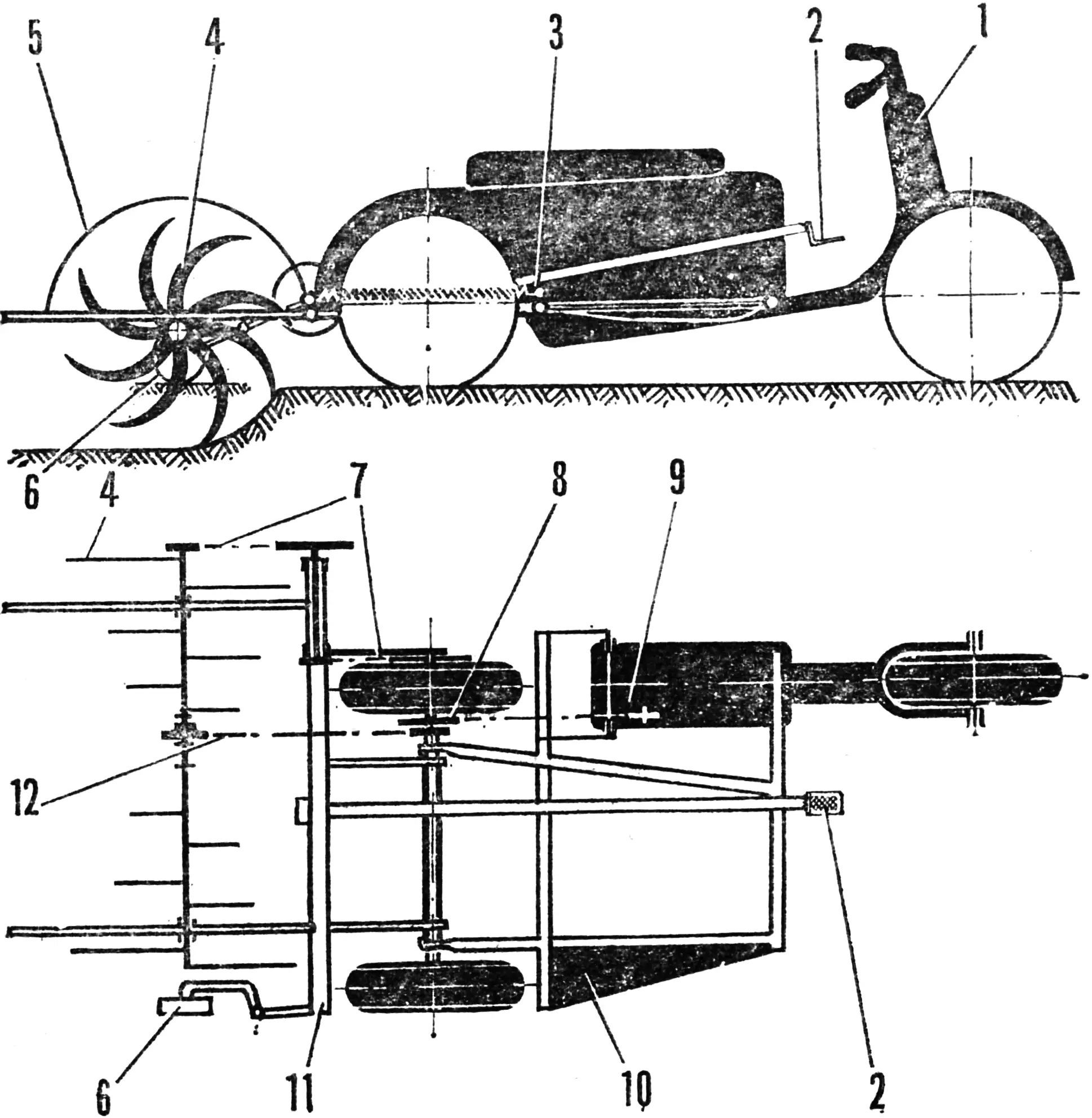
1 — moped, 2 — rotary tiller lift pedal, 3 — spring balancing the rotary tiller, 4 — rotary tiller, 5 — housing, 6 — depth-limiting wheel, 7 — chain drive from rotary tiller to wheel, 8 — double-sprocket, 9 — engine, 10 — trailer frame, 11 — rotary tiller frame, 12 — chain drive from engine to rotary tiller.
The trailer running gear is a hollow shaft resting on the lugs of the frame’s longitudinal tubes and secured in them with clamps.
Mounted on the shaft are: wheel hubs with No. 206 bearings and spacer bushings, a double-sprocket for driving the working tool (its housing is similar in design to the left wheel hub), a drive sprocket, and a rotary tiller lift pedal.
The latter’s frame is welded from tubes and steel plates and is mounted on the trailer at three points. It carries the rotary tiller — a block of bushings with curved, sharpened tines welded to them.
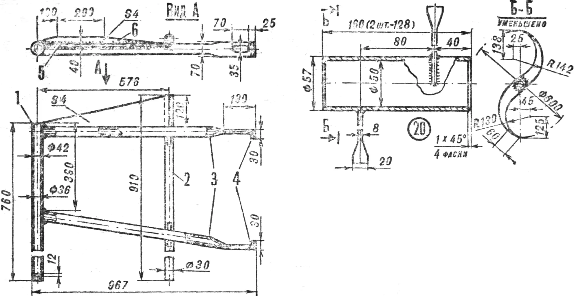
1 — front cross tube, 2 — rear cross tube, 3 — longitudinal tubes, 4 — lugs, 5 — horizontal gusset, 6 — vertical gusset.
The rotary tiller is assembled as follows (Fig. 4). Tubular shaft 19 is fitted with bushings 20 with tines, hub 21 with a sprocket, No. 210 bearings and their half-housings 22, between which links 23 with bell cranks 24 are clamped. The assembled block is pre-tightened with screws 27, the left one of which is fitted with sprocket 28 (when working dense soil, the number of its teeth can be reduced from 8 to 7 or even to 6).
For even rotary tiller operation, the tines should be arranged around the circumference so that they enter the ground in pairs on the right and left. After that, screws 27 are finally tightened and the bushings are secured to the shaft: seven holes are drilled for bolts 25 and one for the torque-limiting bolt 26.
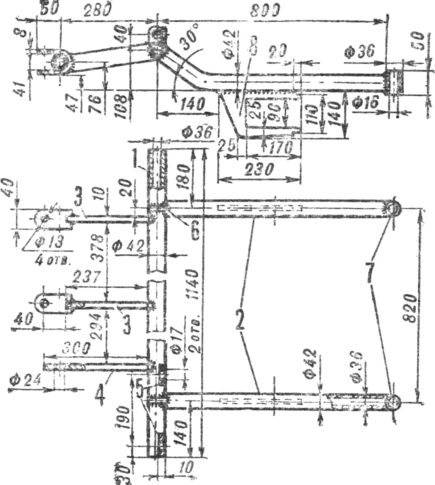
1 — main tube, 2 — load-bearing tubes, 3, 4 — mounting points on the trailer frame, 5 — lugs for securing the intermediate shaft housing, 6 — loop for the housing, 7 — bushings for installing depth-limiting wheels, 8 — bracket for mounting the rotary tiller shaft.
The rotary tiller is placed in frame brackets 16, chains 29, 33, and 34 are fitted, and their tension is adjusted with intermediate shaft screws 31 and links 23. Bracket 17 with depth-limiting wheel 18, which sets the soil working depth, is installed on the right end of frame 16. Pedal 35 is fitted, and the rotary tiller is balanced with a spring.
The assembled mechanisms are checked, lubricated, and turned by hand with the unit raised. You can start the engine and begin cultivating the household plot. Movement should be in circles, and the working tool’s speed should be kept steady with the throttle; otherwise the tillage will be uneven. On dry soil, uniform tillage depth is achieved by installing two more depth-limiting wheels 18 on the ends of frame tubes 16.
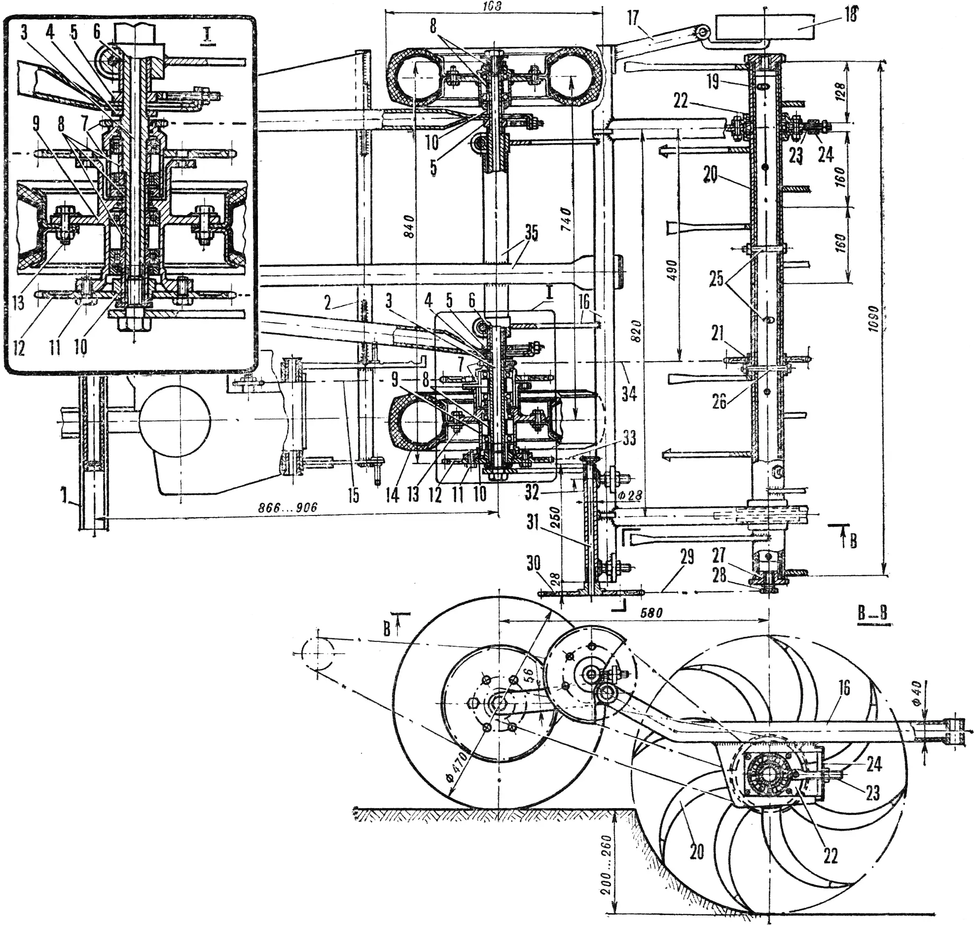
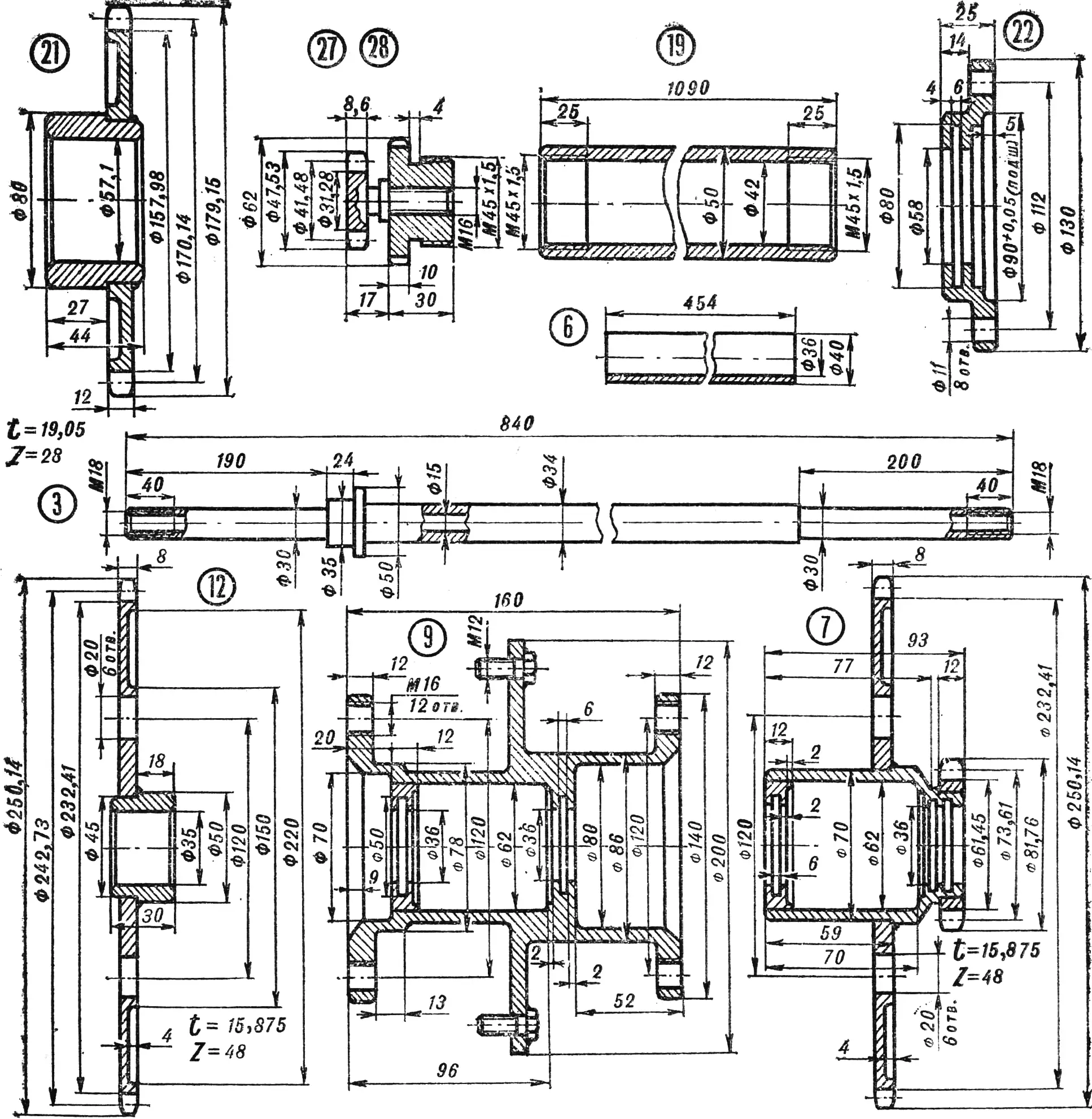
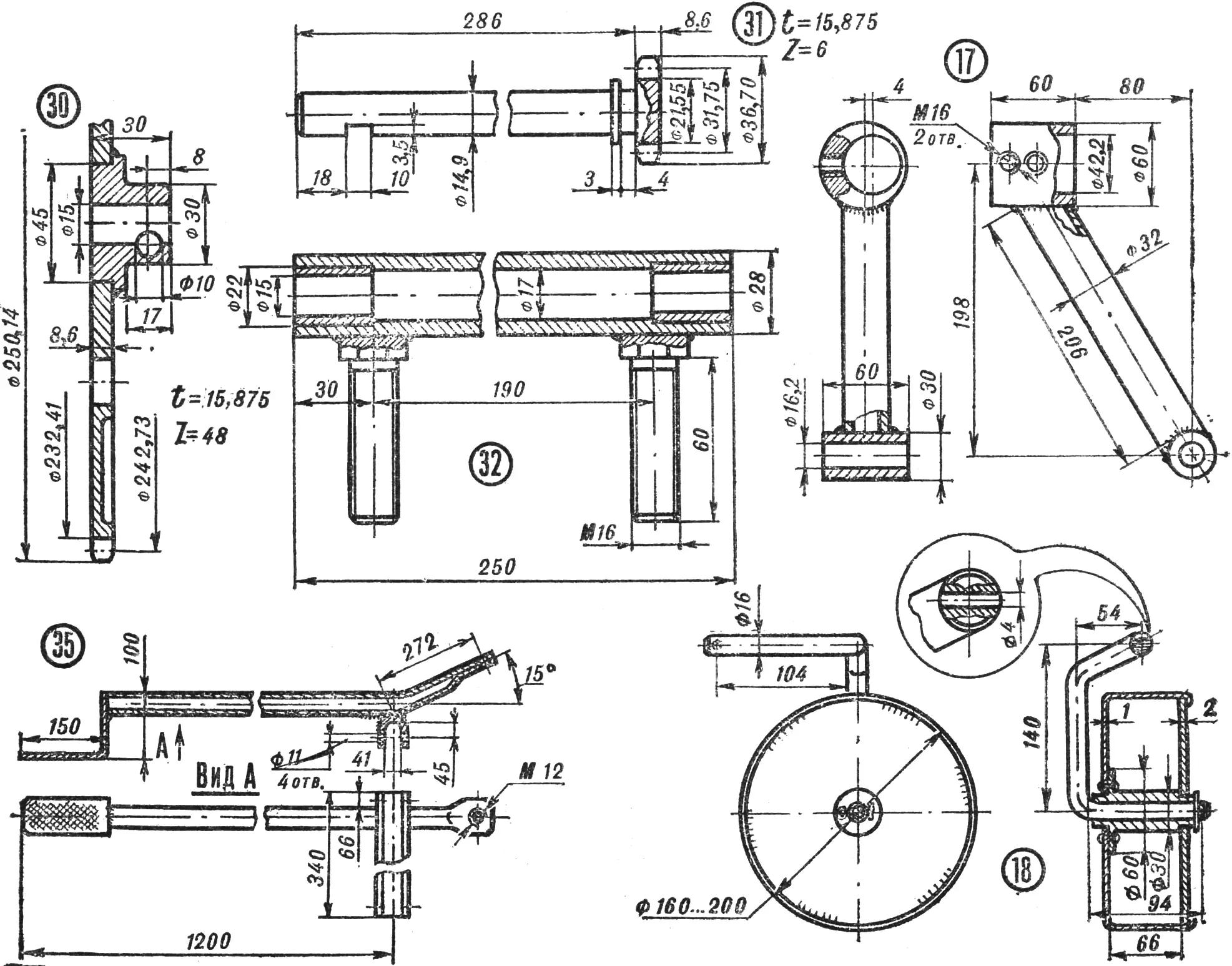
1 — moped frame, 2 — trailer frame, 3 — trailer shaft (steel 45), 4 — washer, 5 — clamp (steel 35), 6 — spacer tube, 7 — double-sprocket (steel 45), 8, 10 — spacer bushings (steel 3), 9 — hub (steel 3), 11 — screw, 12 — drive sprocket (steel 45), 13 — wheel mounting bolts, 14 — wheel, 15 — drive chain (pitch 15.875 mm), 16 — rotary tiller frame, 17 — bracket. 18 — depth-limiting wheel, 19 — tubular shaft, 20 — bushings with tines (steel 45), 21 — hub with sprocket (steel 45), 22 — bearing half-housings (steel 3), 23 — link (steel 35), 24 — bell crank (steel 3), 25 — mounting bolts M10, 26 — torque-limiting bolt M8. 27 — screw (steel 3), 28 — sprocket (steel 45), 29 — transmission chain (pitch 15.875 mm), 30 — sprocket (steel 45), 31 — intermediate
On turns, when driving over an obstacle, or when the engine is overloaded, the rotary tiller is raised with the pedal. If engine power is insufficient, the outer cutters are removed. When moving from one plot to another, chain 34 is removed and screws 11 are moved to sprocket 7.
It may happen that, to increase the unit’s passability, the wheels will need to be locked together.
Turning a moped into a tractor no longer surprises anyone: home-built motor transport has long been a common base for such designs. But being able to easily turn the tractor back into a moped after finishing work in the vegetable garden or orchard is, without doubt, a design breakthrough by our reader A. Gordin.
Indeed, is it really necessary to multiply engines on one’s farm? Is a separate self-propelled agricultural unit needed? Would it not be better to have a universal drive for various working tools that ease labor on a household plot?
We invite skilled builders who have made such designs to share their experience: send photographs, drawings, and descriptions of the universal small-scale mechanization tools you have created. We also await such materials from leaders of agricultural design clubs and young technicians — participants in the magazine’s “Small Mechanization” competition — for the best designs of auxiliary mechanisms, attachments, and hand tools for work on household plots and in school experimental farming.
«M-K» 10’84, A. GORDIN
Recommend to read
 WALK-BEHIND WHEEL
For simplicity, I decided to make the walk-behind, in-parzych, unicycle, and secondly, on the basis of units, components and parts of various machines manufactured in the factory. Took... ACCORDING TO THE PRINCIPLE OF COMMUNICATING VESSELS
...it is possible to make a device for determining the marks in the construction of garden buildings. For this you will need a long hose with transparent bits filled with water.
