INSTEAD OF SHOVELS – MICROCABIN

INSTEAD OF LAPATI - MICRODOMAIN“Hello, dear editors! Write “M” from 1969. Drawing magazine has fulfilled a number of projects. Pleased with them, that is, on all hundred. Particularly pleased with microtracker Amurchonok, has become my reliable assistant. He will plough the ground, and weeding perform, and hilling plants with it — no problem. And required construction works: load, which should drop the mortar (concrete) is thoroughly kneaded. I would like to equip your microtracker potato. The same as in the photo stitch “M-K” 5’89. If you publish the blueprints, then the fall will have time to do everything. To harvest potatoes to carry on their plot for not using old-fashioned shovels, and a modern, mechanized way.

Letters with a similar request to the editorial office received a lot. The response to them is published below the joint author of the material that interested readers design potato digger and a special correspondent of our magazine.
 
we offer design is intended for mechanical harvesting of potatoes. Moving behind microfractures in the aisles, this trailer unit a spade-like blade “rips” the soil (to a depth of 100 to 120 mm), digging tubers. Together with the land and leaves they lean on the chain-rod conveyor of the Elevator. The earth is sifted, and potatoes, cleaned from the remnants of the stems in a rotating drum, a row is placed at the rear. In parallel, twisted lies almost in the rope plant.
 
Loss and damage to the crop is reduced to a minimum thanks to the sophistication and reliability of the design, and the appropriate track width of the tractor used, the distance between the wheels supporting-the hub of potato digger aisles. In this case, 2×560= 11 20 mm and 560 mm (see figure).
The basis of the kinematics trailed potato digger PKM are gimbal (steering of Trantor T-40), two sets (of the scooter “Tula 200”), two chain-rod (based on roller chains for agricultural machinery DWP-38 — for the Elevator and drum cleaner) transfer and an angular gear (from a pick-up stacker differently PC-1.6 And N1:1). Torque is supplied from the PTO of the tractor. As independent support-transport node is taken with the usual transport trolley with composite wheels.
 
Stars used the model with the number of teeth is equal to 9, 14 (from the farm) and 1 7, 38 (of the scooter). However, the hub Z1 uZ4 had to redo several, Z6, Z7, Z11 (Z6′ , Z7`, Z11`) is to plant in single-row radial ball bearings sealed type 180 000.
 
But, of course, is much easier, if we can get the corresponding parts from decommissioned serial potato harvester. Conveyor Elevator somewhat shortened in width. It is removed from the tube. And to achieve that the speed of movement of the chain-rod tape fast-crawling dig shingles of the Bush to the desired size. As for existing industrial potato harvester trays, setting them in the design of the PCM (between the drum and the Elevator) is not provided: the complication in this case can be considered inappropriate.
 
The potato collected on a homemade frame-base. Design here, as it can be seen from the illustrations, welded. Made from scraps of steel channel No. 8 using ucoin (channel number 5), a steel angle 63×40 mm and 8-mm plates.
 
Trailed potato PKM
 
Trailed potato PKM.
 
 
Layout machine
 
The layout of the machine:
1 — shaft drive PKM, 2 — frame base, 3 — pressure unit, 4 — angular gear box (from a pick-up stacker differently), 5 — shaft drive drum cleaner, 6 — node support-transport, 7 — the drum-cleaner, 8 — Elevator chain-bar with shingles.

 
The kinematics of the potato digger
 
Kinematics of a potato digger:
1 — PTO mini tractor, 2 — shaft drive PKM, 3 — shaft reduction input node 4, the input shaft angular gear (from a pick-up stacker differently PC-1.6 A), 5 — output shaft of the reducing node, 6 — transfer of gimbal (steering of the tractor T-40), 7 — node, support-transport (based on transport truck), 8 — shaft of the input drum cleaner, 9 — axis stars “squirrel cage” (2 PCs.) 10 — shaft of the Elevator, 11 — axis of the sprockets of a chain-bar conveyor.

 
Frame base
 
Frame base:
1 — plate charms (the strip 80x40x8 mm, STD, 2 PC.), 2 — front suspension (steel channel No. 8), 3 — longeron (channel steel # 8, 2 PCs), 4 — kosina (channel steel # 5,2 PCs), 5 — plate mounting support-transport node (Vs, 2), 6 — the riser of the drum-cleaner (8-mm steel plate, STZ), 7 — cross-member-support rear (steel area 63×40 mm).


Pressure node
 
Pressure node:
1 — plug the propeller shaft (from the steering control of the tractor T-40, 2 PCs.). 2 — shaft (Steel 45), 3 — dowel prism 6x6x12 mm, Steel 45, PL. 3), 4 — nut M27 (2 pieces) 5 — washer (2 PCs.), 6 — sprocket Z1=17 weld (scooter “Tula 200”), 7 — hub (Sgal 45), 8 — thrust (2 piece), 9 — 180 206 ball bearing with seal (2 PCs), 10, body ugolka (Steel 30), 11 — sprocket Z2=17 (of the scooter), 12 — weld plate (5-mm St 3.2 CPU.), 13 — asterisk Z4=38 (of the scooter “Tula 200”), 14 — hub-hub (Steel 45), 15 — key 5x5x10 mm prismatic (Steel 45,2 PCs.), 16 — shaft driven (Steel 45), 17 — thrust (PT 3), 18 — M5 screw (4 PCs) 19 — washer lock (4 PCs), 20 — lid (St 3), 21 — spacer (PT 3), 22 — enclosure-glass (Steel 30).


Mount the reduction of the node (option)
 
Mount the pressure reducing unit (option).
 
 
Drum cleaner
 
The drum-cleaner:
1 — 1790 mm chain roller PRD-38 (2 PCs), 2 — drive chain tension (from 1760 mm cut area 20×20 mm, 2 pieces) 3 — terminal welded axle sprocket “squirrel cage” (Steel 45, 4 PCs.), P1 — based weld axis stars “squirrel cage” (628 mm cut water-gas supply pipes 33,5×4, reinforced, 2 PCs.), 4 — disc support (steel area is 36×36 mm, curved, 2 PCs.) 5 — plate reference (V. 5, 6 pieces) 6 — star socket under the ball bearing (4-piece), 7 — 180 206 ball bearing with seal (6 PCs.), 8 — asterisk input (master) of the shaft (2 PCs), 9 — bearing-Cup bearing (Steel 30, 2), 10 — terminal “squirrel cage” (47 PCs), 11 — shell protective (scrap rubber hose, 47 PCs.), 12 — welded end of shaft (Steel 45,2 PCs.) 12′ — the basis of a welded shaft of drum cleaner (568 mm section of pipe 33,5×4 enhanced water-gas supply), 13 — spar (588 mm section of steel area of 36×36 mm, 3 PCs.), 14 — flange (STZ), 15 — a plug of a propeller shaft (from the steering control of the tractor T-40).


Base-transport:
 
Node support-transport:
1 — axis (Steel 45), 2 — flange (St 5,2 pieces) 3 — wheel Assembly (t transport truck, 2 PCs.), 4 — the bearing housing (Steel 20, 2), 5 — 202 ball bearing (4 PCs.), 6 — bearing-suspension (130 mm cut steel angle 60×40 mm, 2 pieces), 7 — nut M8 (8 PCs.), 8 — split washer (8 PCs), 9 — bolt M8 (8 PCs.) 10 – M12 (4 square), 11 — Grover washer (4 PCs), 12 — nut M12 (4 holes) 13 — frame base PCM.

 
Elevator
 
 
Elevator:
1 — the ploughshare (from the paintings circular saws or 5-mm Steel 9KHS), 2 — the jacket (2.5 mm St 3) a 3 — node input axis of a chain-bar conveyor), 4 — 1670 mm feed conveyor (based on roller chains PRD-38, 2 PCs.), 5 — Poloz (PTFE-4D, 2 PCs.), 6 — beam structural reinforcement (channel No. 8 steel, 2 PCs.), 7 — pole (Article 3, 2), 8 — the driveshaft, 9 — solitaire (V. 3).


The input axis of the chain-rod conveyor
 
The input axis of the chain-rod conveyor.
 
Driveshaft Assembly
 
The driveshaft Assembly:
1 gear Z=18 bevel gear angular, 2 — node bearing reducer, 3 — pillar of left side cover, 4 — Board casing left, 5 — spacer ring (30-mm section of the tube 38×4 seamless cold-drawn steel), 6 — bushing (145 mm 38×4 pipe cold drawn seamless steel), 7 — shaft of the Elevator leading (Steel 45), 8 — dowel prismatic 8x7x45 mm (Steel 45,2 PCs), 9 — sprocket Z=14 (farm equipment, 2 PCs.) 10 — ring-a shorting bar (17-mm section of the tube 38×4 seamless cold-drawn steel), 11 — Board casing right, 12 — pillar of the right side of the casing 13 is a Cup-bearing (V. 5), 14 — bearing cap clamping (St 5), 15 — washer grower a 16 — nut M24,17 — ball bearing 180 206 with a seal (3 piece), 18 — bolt M12 (8), 19 — split washer (8 PCs), 20 — nut M12 (8 PCs.).

 
Of 5-mm plate (Steel 9KHS) is made and share. But it can be cut out of cloth of a circular saw will work just as good. Four bolts having heads “under flush”, the ploughshare is attached (hence, the possibility of replacing if needed) to the hard casing of the Elevator is delayed and mysteries. Oval sharpening (30°) allows the working body to do without a large depth. After the mechanized hilling is often quite enough that it does not go beyond 100 to 120 mm. it is almost completely eliminated cuts the tuber.
 
You can change the tilt of the Elevator (hence “angle of attack” of the blade) by varying the attachment of the casing n frame-based (illustrations not shown), as, indeed, reduction and fixation of the node.
The design of the latter (see Fig.) unauthorized. Consists of rigidly connected to each other cylindrical housings: bushing and Steel glass 30. They rotate on ball bearings leading and driven shafts of Steel 45 with prismatic impaled on a dowel with asterisks.
 
As already mentioned, the hub of the sprocket ^(Z1=17 and Z4=38) welded. The technology of manufacture of such with sufficient completeness has already been covered by the journal (see, for example, “M-K” 5’91). Moreover, as the hub for the Z4 can take a 25-mm segment of reinforced steel water-gas supply pipe 33,5×4.
 
Perhaps the most difficult to manufacture in a “home Studio” would be a drum-cleaner. It is based on two 1790 mm roller chains PRD-38. More precisely — 94 link located on their axes, and on the ends 47 of the rods with a protective (to prevent damage to the case tubers) shell in the middle. For tensioning the resulting “squirrel cage” and giving it a certain strength are two diene bent from 1 760-mm segments previously tempered steel area 20×20 mm. And the welding is performed after the tensioning of the chain.
 
But you can do two rims from a teen bike, if any you have at hand will be. On the bottom, using clamps “squirrel zero” stretched and welded item. For even greater rigidity of the structure can be reinforced by welding bars (10… 12 mm) grooved fittings.
 
“Squirrel cage” rotates, sandwiched between asterisks, located on the two axes and the shaft (fixed on the supporting diene with six welded plates). And axis, and the shaft is composite. Made with the same technology and represent the water-gas supply pipe of appropriate diameter, both sides have end caps welded from Steel 45.
 
Both axes not moving. Welded and base plates. But the driven sprockets on the axles rotate as the sleeve each mounted on the outer cage of the ball bearing 206 18S. The axes are welded to the base plates after the overmolding ball bearings with sprockets and adjusting their position. As for the shaft it revolves on bearings 180 206. And with it, rotate and leading asterisks, forcing him to spin and the drum itself. To “input” the leading star of four screws M10 flange with welded thereto a propeller with a fork.
 
Similar design has the shaft of the Elevator. Sprocket Z=14 rotate together with it, being planted on the prismatic dowel 8x7x45 mm and clamped from the sides by using spacer rings and sleeve, made of segments of cold drawn seamless steel tubes. Bevel gear welded to the shaft. Fit a pair of bearings in the gearbox housing is made deaf; fastening the housing to a support is carried out by bolts M1 2.
 
The input axis of the chain-rod conveyor resembles a threaded bolt M24 at the end. The axle is inserted into the hole of the casing on the left side. Then put spacer, and followed by the bearing from 180 205 is pressed onto its outer MAG sprocket Z=14. Put on the intermediate sleeve, the second bearing with sprocket, spacer ring. And after this is inserted the axle into the hole in the casing on the starboard side. The fastener ends a mystery M24 with washer.
 
Chain-bar tape — it is like a modified (stretched) “squirrel wheel”. It is made on the basis of two 1670 mm roller chains PRD-38. But bars here are somewhat less (44 PCs.). On top of that they are shorter “squirrel”: 275 mm. For the best slip tape on the slide, it is made of PTFE-4D. Enshrined it on the beam of the structural reinforcement using four screws MB with countersunk head. Located on the sides of the casing of the Elevator, the two slides serve as supporting surface for the chain links and protect it from damage.
 
It now remains to consider only the supporting-hub. But it is quite simple in design, and any difficulties in the manufacture hardly anyone can cause. The size and kreplenie parts of clear illustrations.
 
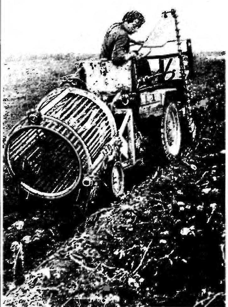
Six-year experience of operation of potato digger PKM and showed high reliability of this design and its advantages are revealed,compared,
 
for example, with a drum auger. While the kinematics has been so successful that the Krasnoyarsk combine plant decided to take it as the basis for the development of mass models. But that’s something not seen one. But we have to be nerazvorotlivy factory workers, as they used to.
 
E. SVIRIDOV, Krasnoyarsk, N. KOCHETOV, our special. Norr.

Recommend to read

  • SOLDERING IRON-ECONOMYSOLDERING IRON-ECONOMY
    Repair of electronic devices in radio is associated primarily with the need to restore the holes and the possibility of damage to conductor paths of printed circuit boards. We offer...
  • MAGNET HAMMERMAGNET HAMMER
    To fix the drawing paper on the drawing Board, a Board which is made of particle Board, is difficult. For anchoring one corner you have to use some drawing pins, as they bend. If you use...