PARITEL ‘ CLASS A1

Soaring leader CLASS A1
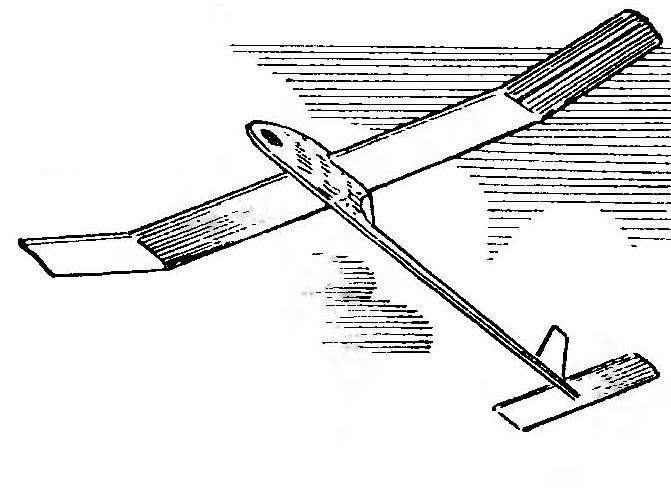
The proposed model glider created based on ideas… not to be used as a construction material balsa and composite materials. The supporting plane of the apparatus — traditional design. Despite the lack of hard cladding nose part of the wing, consoles have sufficient rigidity on twisting. When the geometric proportions corresponding to the best representatives of this class, the model makes a good start with Leer and reliable planning with winds of up to 7-10 m/s. At high accelerations on consoles is not excluded for arbitrary twist, so it is not recommended to install on the glider towing hook with automatic dynamic start.

The most time-consuming part is the wing, consisting of two consoles. Each of them formed by the wing and ear. The profile of the wing center section on a constant, like a-8306-S. It is supported by the ribs 26 of the veneer of lime. The “ears” of the wing is trapezoidal and similar profile. Rib “ears” are cut separately on the profile template by the method of successive stepwise displacement of the pattern of the upper and lower parts of 2.5 mm.
 
For ribs will fit the veneer and some varieties of mahogany, which is used in finishing furniture. The thickness of the applied workpieces 0.8 — 1.2 mm. These ribs are useful to cover the two sides with a layer of nitrocellulose lacquer to reduce warping from moisture.
 
Console going in the stocks. It fixed two-rack-and-pinion front and rear edges, and glued the finished ribs. The shanks of the ribs be sure to glue in the slot trailing edge of a wing 1.5 — 2 mm. After Assembly, the frame edge being profiled.
Stabilizer model design and further explanation is not required. All-moving keel has a frame made of strips of a cross section of 3×3 mm. other options are: Styrofoam, corrugated box cardboard, drawing paper, etc. the Drive is provided by the line of 0.3 mm, stretched by the ring rail on the tow hook. When towing the keel is located exactly on the axis of the fuselage, and in planning a flight it is rejected until it stops and sets a trajectory of steady turn.
 
Plating of bearing surfaces — micuenta paper coated with nitrocellulose lacquer or Mylar film with a thickness of 20 — 25 microns. For covering of the stabilizer and fin will approach the film thickness of 10-15 microns. When using macalintal paper wing is retained by clamps in the stocks during the month. On the left console at the rear edge of the twist is given to “lug” up to 4 mm, and on the right by 2 mm only center section. At a distance of 7 mm from the leading edge of the wing is glued to the thread of the baffle thickness 0.5 — 0.7 mm. the Angle of attack of the wing is+2°, the stabilizer is approximately -1°. Fine adjustment is carried out when the debug starts with the hands.
 
The geometrical parameters of the glider
The geometrical parameters of the glider.


The profiles of the bearing surfaces of the model
 
The profiles of the bearing surfaces of the model.
 
 
Console wing
 
Console wing:
1 —solitaire (plywood, thickness 1.2 mm, each of 10— 12 mm), 2 — ending console (Linden, thickness 3 mm) 3 — shelf side member (pine, 2×5 mm), 4 — front edge (pine, two strips: 2×5 mm and 3×3 mm), 5 — area (plywood, thickness 1.2 mm), 6 — rib (Linden, thickness I mm) 7 — wall of side member (plywood, thickness 1.2 mm), 8 — axis holes for the wing mounting pins, 9 — root rib (plywood, thickness 2.5 mm), 10—trailing edge (pine, 10×2 mm), 11 —a connecting rib (Linden, thickness 3 mm), 12 — power rib (plywood, thickness 1.2 mm).


Stabilizer
Stabilizer:
1 — ending (lime, thickness 2 mm), 2 — solitaire (plywood, 1,2 mm thickness, sides 7 mm), 3 — the front edge (pine, 3×3 mm), 4 —longitudinal (pine, 3×2 mm), 5 — rib (Linden, thickness 1 mm), 6 — pin (bamboo, 0 2 mm), 7 — the Central rib (Linden, thickness 3 mm), 8 — trailing edge (pine, 6×2 mm).


Fuselage Assembly
Fuselage Assembly:
1 — load balancing (tin or lead), 2 — nose part (Linden, 10 mm thick), 3 — the front pin fastening the wing panels (wire OVS 3 mm), 4 — back pin (wire OVS 2 mm), 5 tail beam, 6 — Kiel, 7 — the axis of rotation of the keel (wire OVS 1.5 mm), 8 — bearing stabilizer (plywood, thickness 1.2 mm), 9 — adjusting pad, 10 — hooks wick (wire 0,8 mm), 11 — stud fastening MZ the start of the hook (wire OVS 3 mm).

 
The fuselage of the glider consists of the bow and the tail boom. The nose part is very simple, it only attached balance weights, hook rails start and the hinge rods wing panels.
 
Tail boom is made of dense grained pine or spruce. Section it — 10×12 mm in the root portion and a 5,5×4,5 mm at the end. With nose connects “us” with epoxy.
 
The entire surface of the fuselage is painted with a waterproof paint or coated with a nitrocellulose lacquer. Starting the hook — side type, it is made of wire or dural area.
 
In the drawing, the glider shows a wick system determinatio stabilizer. In our opinion, it is most simple and convenient for the runs of the model during training and competitions. Application timer from the camera brings a lot of hassle when setting up and adjusting of the mechanism and system of determinization. Time spent on such work, it is enough to build a spare set of wing panels.
 
NOVIKOV,
the head of the circle

Recommend to read

  • SHARE EXPERIENCESSHARE EXPERIENCES
    It is known that if two are going to swap, say, apples, then in the end they will still be an Apple. Well, if these two will exchange ideas, then each will have two ideas... This idea...
  • FOUNTAIN PEN PAPERFOUNTAIN PEN PAPER
    Simple and beautiful ball-point pen can be manufactured in a few minutes, if there is a rod with pasta and... a colourful illustration from a magazine or just a sheet of paper. For this...