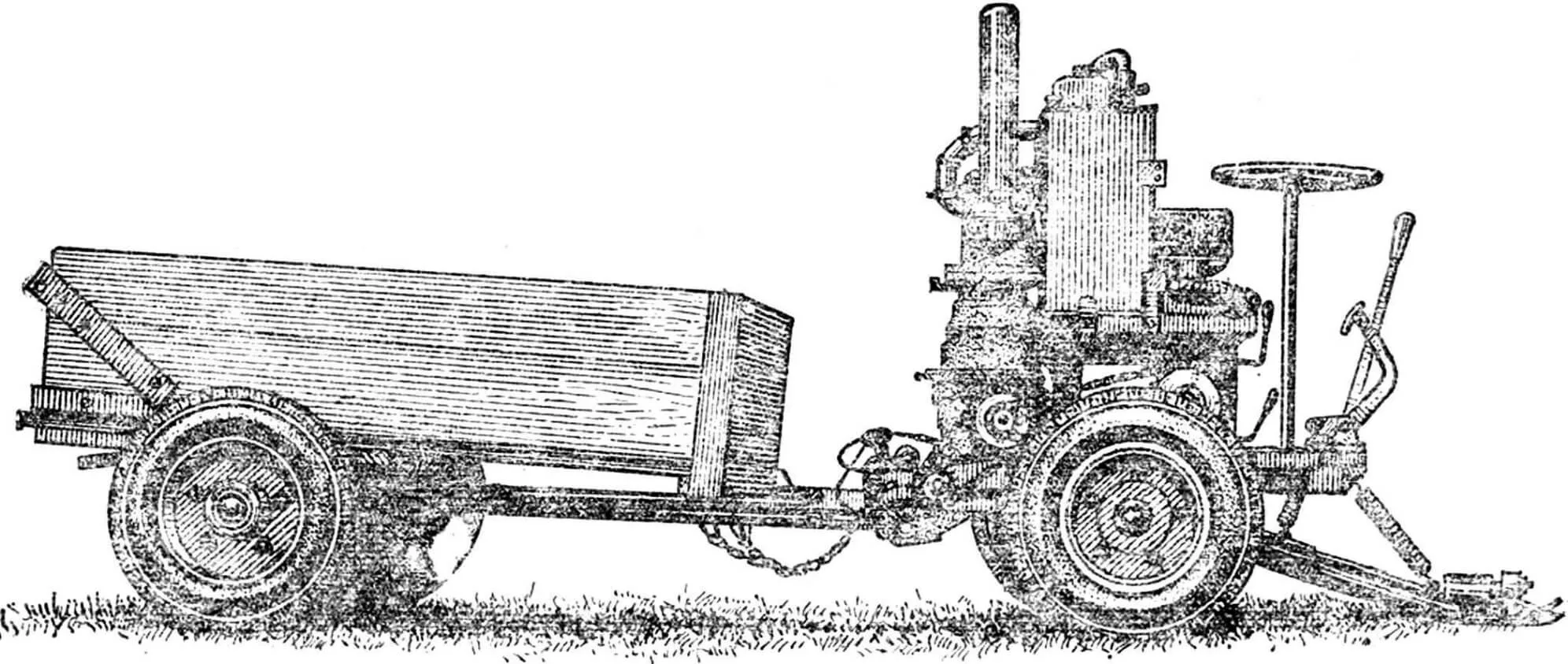
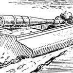
— How to explain such a “hybrid” — a two-wheeled mini-tractor and a single-axle cargo cart on a rigid hitch? Doesn’t a mini-tractor have more capabilities with the same four wheels? — those who got acquainted with my mechanical assistant usually asked.
The question is not idle: it reflects interest in the features of the chosen unit scheme. It’s not just about engine power. With the small dimensions of the structure, the PD-10 I installed is quite sufficient for agricultural work on our lands. The main thing is that I managed to compactly place the units in the machine, using the principle of vertical connection — assembling them on “one axis”. And as a result, it became possible to install a driver’s seat here (by the way, that’s why it’s a “mini-tractor”), which means making a more convenient steering wheel control. Being on a trailer, and a loaded one at that, and controlling from there, holding the walk-behind tractor levers in your hands, as often happens, is far from simple.
Other advantages — lower metal consumption, greater power-to-weight ratio, reduced specific fuel consumption. Placing the driver over the drive axle increases wheel grip on the ground. Good maneuverability is ensured by a short two-axle base, while a “traditional” mini-tractor with a cart would have at least six wheels and three axles.
The mini-tractor can not only plow, cultivate crops, but also be used as a drive for various mechanisms. I also adapted it for mowing.
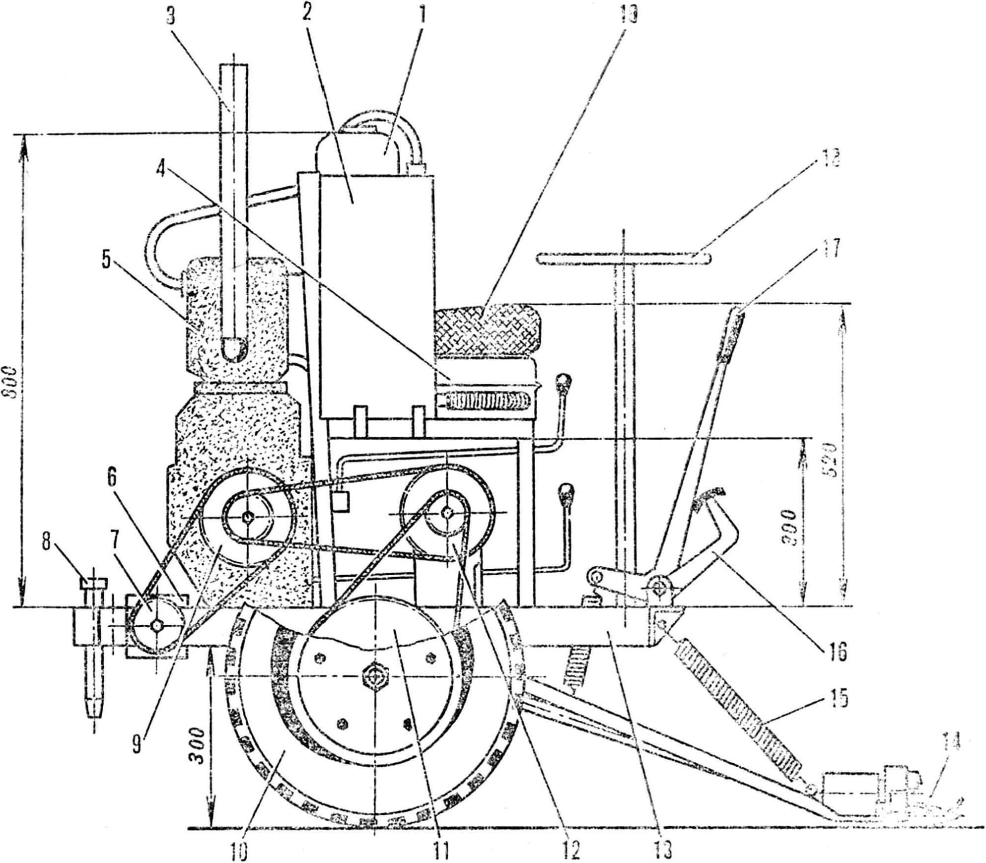
1 — fuel tank, 2 — expansion water tank, 3 — muffler, 4 — main water tank, 5 — engine, 6 — mower drive bevel gear housing, 7 — power take-off shaft sprocket, 8 — kingpin, 9 — engine output shaft sprocket, 10 — wheel, 11 — wheel axle sprocket, 12 — intermediate shaft sprocket, 13 — frame, 14 — mower, 15 — compensator spring, 16 — brake pedal, 17 — mower lift lever, 18 — steering wheel, 19 — driver’s seat.
Working out this option gave me, perhaps, the most trouble. The fact is that I initially hung the mower on the side. But this increased the width of the unit: it was difficult to mow grass in forest belts and sparse forests, even to drive along field roads to the work site. In addition, the strong vibration of the mower was disturbing. Therefore, it had to be moved forward. At the same time, I changed the drive. If earlier its scheme was similar to the combine harvester drive, now I installed the crank directly on the knife mechanism itself. Control became easier from this, and the vibration disappeared. The mounting time was also reduced. True, the weight of the drive increased somewhat, which forced me to install stronger compensator springs for the mower weight.
From a broken wing from wide-cut rakes, I made mini-rakes, placed them at the back on the cart body and equipped them with a lifting lever. This mechanized the next stage — windrow pickup. In addition, sparse grass became not scary. In such places you work, and it seems like nothing is left behind you, but I attached mini-rakes — after ten or twenty meters I collected at least a small pile.
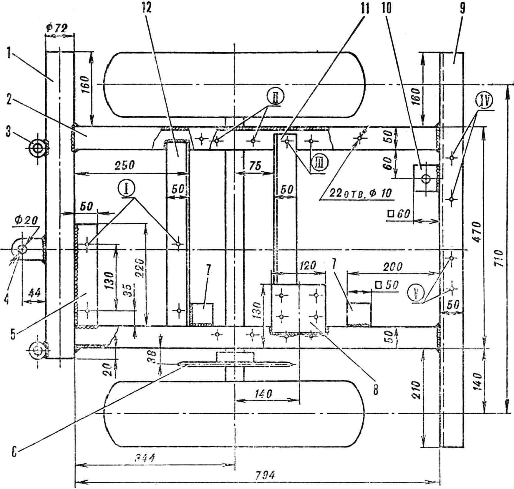
1 — power take-off shaft pipe (pipe 72X3, length 650 mm), 2 — longitudinal channel, 3 — turn limit chain eye (pipe 36X8, length 50 mm), 4 — hitch eye, 5 — engine mounting plate, 6 — wheel axle sprocket, 7 — seat mounting bracket, 8 — intermediate shaft bearing housing mounting plate, 9 — front angle, 10 — steering wheel support, 11 — brake band anchor angle, 12 — cross angle.
Bolt mounting holes:
I — engine, II — wheel axle bearing housing, III — mower suspension eyes, IV — steering cable drum, V — control lever axle.
Most parts and units are from decommissioned agricultural equipment. I took the mower blade from a wide-cut tractor mower, adapted the drive connecting rod from it, and used the crank from a horse-drawn mower. The suspension levers are former longitudinal steering rods from a combine with mounting forks at one end (corresponding eyes from the same rods). You can also pick up the crank shaft bearing housing from it, but the whole unit turns out to be somewhat heavy because of this: it’s better, of course, to make a simpler one. To install it, I welded an additional plate to the knife blade. By the way, in my version, the knife has 18 fingers. Positions 20 through 23 are occupied by the connecting rod, that is, the blade is cut off after the 23rd finger.
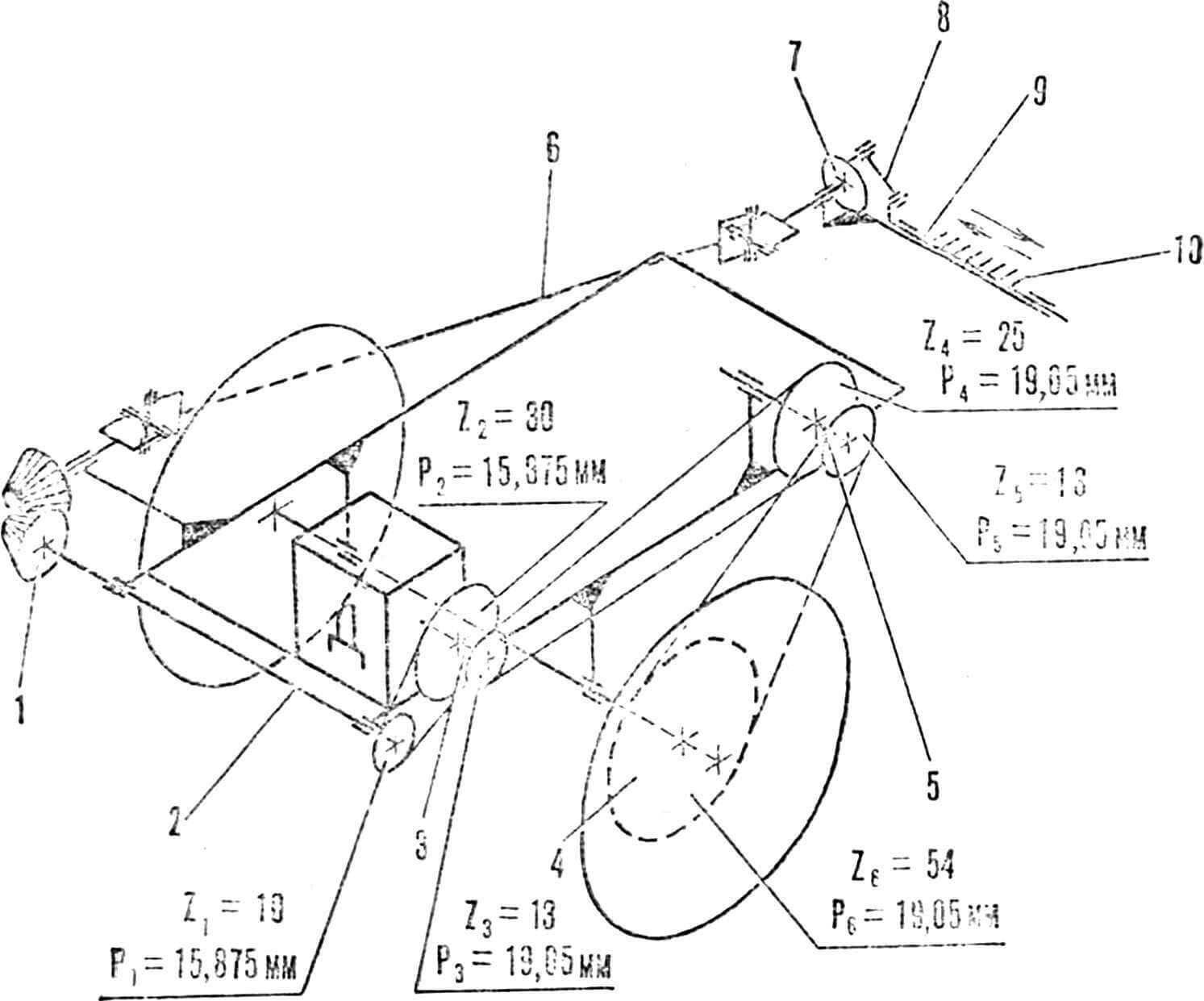
1 — mower drive bevel gear, 2 — power take-off shaft, 3 — engine output shaft, 4 — wheel axle sprocket, 5 — wheel drive intermediate shaft, 6 — driveshaft, 7 — crank wheel, 8 — connecting rod, 9 — guide, 10 — knife.
To control the mower position, a lift lever is installed to the right of the seat, and in such a way that it works “away from you”: it became possible to use a foot pedal as well.
Eighteen working fingers leave some reserve of engine power for mowing on a slope — “uphill”. I can advise those who live on the plains to slightly increase the blade length by 2—4 fingers.
The engine of the mini-tractor provides working speeds of 3 and 12 km/h.
1 — frame, 2 — brake band, 3 — wheel axle, 4 — brake drum, 5 — brake band anchor angle, 6 — mower suspension eye, 7 — brake rod.
The track of the walk-behind tractor and cargo cart is different — 710 and 1100 mm respectively: I consider such a “train” more stable. Wheels from SZA. I installed a gearbox from a DT-54 tractor. Cooling is water-cooled, with circulation through expansion and main tanks. The fuel tank is homemade, fuel flows from it by gravity.
Gear shift and clutch levers are brought forward for convenience — in front of the driver’s seat. However, it is necessary to provide for their duplication in this case, placing the same levers at the back of the unit as well — for control from the “ground”.
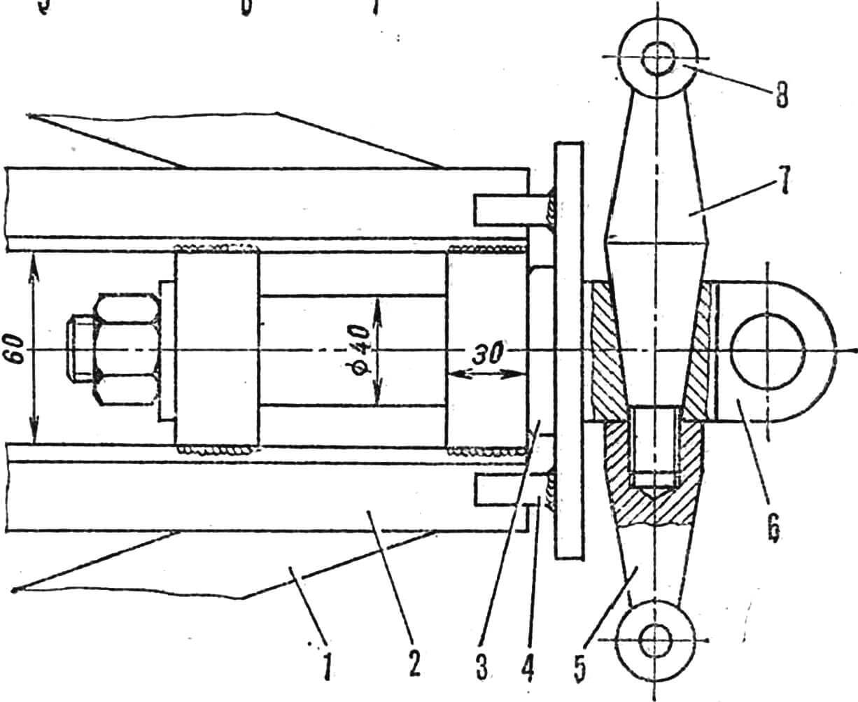
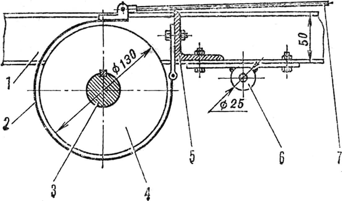
1 — drawbar frame, 2 — hub, 3 — steering knuckle, 4 — cart roll limiter, 5 — pin-lever, 6 — kingpin fork, 7 — transverse rod lever, 8 — steering cable mounting head.
The frame consists of a front beam — 50X50 mm angle, two side channels and a transverse pipe Ø 72 mm. For engine installation, a 50 mm wide plate cut from a 6 mm thick metal sheet and a 50×50 mm transverse angle are provided. The steering pulley brackets, additional shaft bearing housings, and seat mounts are also made from metal sheet. Holes for mounting all units on the frame are drilled Ø 10 mm.
Transmission. The drive of the drive wheels is carried out through a two-stage gearbox, and the power take-off shaft drive — through a single-stage gearbox, bevel gear pair and driveshaft. Most transmission parts are used from decommissioned agricultural machinery.
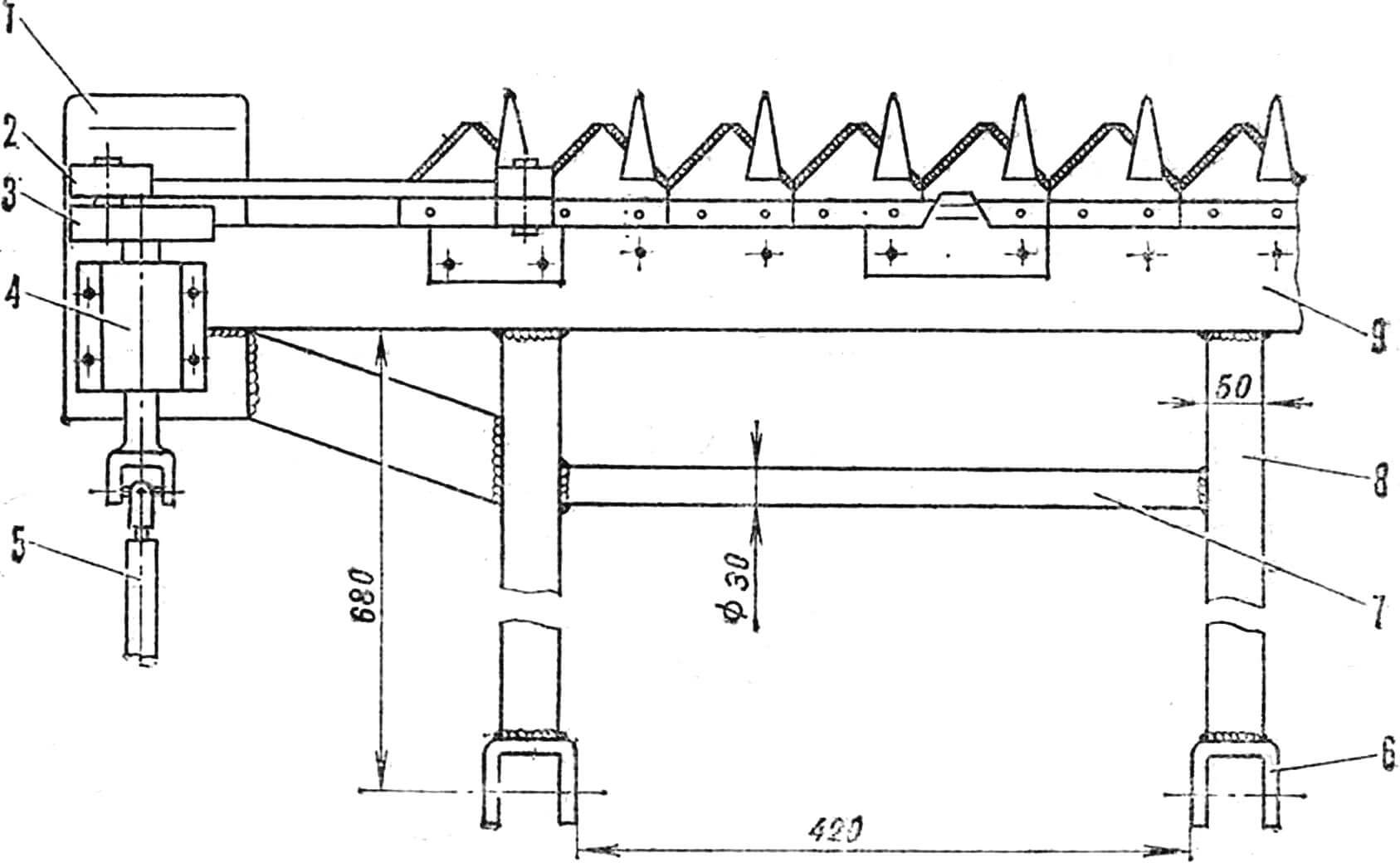
1 — safety “sleds”, 2 — connecting rod, 3 — crank wheel, 4 — bearing housing, 5 — drive shaft, 6 — rod eye, 7 — suspension crossbar, 8 — rod, 9 — mower.
The brake is band-type, tension-type, from SK-3, but somewhat shortened. It is fixed on a special transverse angle: its connection with the side channels is on bolts together with the mower suspension eyes, and the brake drum is installed directly on the running shaft — the wheel axle.

Steering is cable-operated, with cables crossed to match the direction of steering wheel and wheel turn.
The hitch device of the cart is a steering knuckle used in the GAZ-51 design. The transverse rod lever is preserved, but instead of a nut on the other side of the knuckle, a threaded pin-lever is made. There are also cart roll limiters — protrusions on the knuckle disk — in case of “attempts” to overturn it and turn radius limiters — chain loops. Agricultural implements are attached similarly, only with the help of an adjustable additional rod.
I. SAVARBAYEV
Recommend to read
 “SALAMANDER” CLASS FSR
Today we offer RC modelers a high-speed hydroplane races for long, designed and built by famous Hungarian athlete Istvan of Salim. "Salamander" — the so-called new microtiter — has a... PATRIOT FOR RUSSIA
All-wheel drive SUV UAZ PATRIOT. SUVs are in fashion now. The highway was filled with jeeps of all sizes and kinds — from toddlers, in size far ahead of the domestic "Oka", to giants,...
