Despite the many difficulties of various kinds that occurs at each step of the athlete or Amateur Modeler, RC aircraft not yet “died out” among the mass of the cart. Oddly enough, on the contrary, in recent years they are becoming increasingly popular Probably, this is due to an enduring interest in the most complex kind of modeling and at the same time on our appearance more than the poor modelistica “market” instrument of cooperative production. Not to say that it’s world-class products. But it is “down” above the same “Supramar” and is already able to satisfy the needs of novice and developing athletes — circuit decisions in a number of cooperative rulemaking and receivers close to the Western products.
For every one who was finally able to buy the coveted instrument, immediately the question arises a considerable difficulty: how to lay model? The solution of this problem on the proposed development.
The basic principles that served as the basis when designing the model: sufficient simplicity, accessibility and, most importantly, high performance properties at different flight speeds and specific loads. After creating working drawings and interconnection of the nodes was built three completely geometrically similar models differ from each other only power circuit and motor units (and consequently the specific load on the bearing surface). Tests of the three devices showed that with careful error free performance of the plane, its aerodynamic configuration satisfies the requirements within a wide range. All models without any problems can not run with the chassis, and with the hands; flight even in windy weather resistant; responsive control in all axes, and at smaller angles of deflection of the rudders degree of stability allows trust to fly RC, even for beginners. With a full rudder any modification of a micro-airplane with sufficient power of motor “twists” the basic aerobatics. Very broad opportunities both in terms of initial training and the development of skills of piloting this model with two-channel control (Elevator and ailerons). Of course, anyone can try the classic combination of Elevator and rudder dual-channel option. However, it appears. that such “beginners” not only will be limited by the degree of proteraiotita, but will also bring a number of useless skills in the complicated control principle.
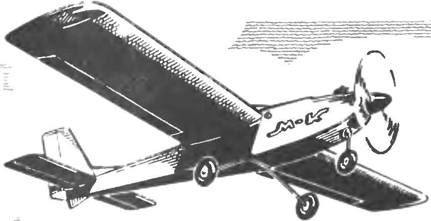
Universal RC model. The main geometrical parameters.
Shown in the figures, the modification of aircraft was the main. It is designed for three-channel equipment (lot side part is about 350 g) and a good, reliable engine KMD. Requirements for high capacity are not required, since takeoff weight is in the range of 1350 grams without landing gear, and thrust enough even for unextended vertical pieces (this is, of course, adjusted the air screw). Lightweight same model in assassina performance have a takeoff weight of about 1000 g and confidently fly even with motors of the “Rhythm” or MK-12V. However, it is still better to use the same KMD, but working in a softer mode.
Fuselage:
1 — motor mount (plywood 6…8 mm), 2 — wedge insert (Linden 4 mm), 3 — front upper stringer (pine 4 mm), 4 — falshstena side of the fuel tank (plywood 1 mm), 5 — cover (dugout detail of lime), 6 — panel bulkhead (plywood 2 mm), 7 — Logement surface (thin foam), the 8 — contour of the wing 9 on Board (plywood 1.2 mm), 10 — jumper sheathing (plywood 1 mm), 11 — pin (beech Ø 6 mm), 12 — upper stringer (pine 4х9 mm for entire length), 13 — frames (plywood 2 mm), 14 — brace (pine 2,5×4 mm) 15 — spacer (pine 2,5×4 mm), 16 – dorsal fin (Linden 2 mm), 17, 23, 30 — items covering the tail node (1 mm plywood), 18 — triangular rail amplification of the junction of the keel with a stabilizer, 19 — edge pine (4×6 mm) 20 — bracing (pine 2,5×4 mm) 21 — ending (Linden 4 mm), 22 — a window for passage of the rods 24, the lower stringer (pine 4×4 mm) 25 — back of the lower sheathing (plywood 1.2 mm), a 26 — base (plywood of 4 mm), 27 — strengthening of Board (plywood 4 mm), 28 — front lower trim panel (plywood 1.2 mm), 29 — arc edge (plywood 2 mm), 31 — the front frame (plywood 5…6 mm) 32 — double-stringer (pine 4х9 mm). If it is possible to reduce the cross section of the rails on part of their length with vibrolance, the main stringers of the fuselage to carry the main section of 5×5 mm and mm. 5×9 Plywood shell elements punch in the slats flush.
Front removable landing gear:
1 — hooks (curved long M3 screws from high-quality steel), 2 — front bulkhead of the fuselage, a 3 — strut of the front wheel (wire OVS Ø 3.5 mm).
Rear removable rack chassis:
1 — strengthening the side of the fuselage (plywood 4 mm), 2 — front part of bottom plating, 3 — rack (wire OVS Ø 3 mm), 4 — pads (steel 1 mm), 5 — screws, 6 — frame (plywood 2 mm), 7 — rear part of the bottom plating 8 is Foundation (plywood is 4 mm).
By construction, all parts and components quite familiar to modelers of any level. Therefore, in the manufacture of RC can not stop attention. I can only say that in any case the main link in the Assembly of power frames and components is used exclusively plasticized epoxy resin K-153. Cover all surfaces of the Mylar film is the average thickness on the glue “Moment” (cutback solvent for nitropaints) or N-88.
Wing (basic version):
1 — tight foam head (thin paper in PVA), 2 — rib (plywood 2 mm), 3 — foam forehead (profile received by the processing unit according to the templates using thermotron; the mass of the forehead of packing foam about 30 g without the plating of the SS-4-40—45 g), 4 — shelf side member (pine 4×5 mm), 5 front flange (lime 2,5×8 mm), 6 — plate splice of the spar (plywood 1.2 mm for the entire height of the profile) 7 — framing of the compartment steering cars (Linden), 8 — polonaruwa, 9—the growing edge (pine 5×9 mm), 10 — power Polonnaruwa (to put in the pin mounting of the wing on the fuselage), 11 — the covering of the wing (plywood 1 mm), 12 — front side member cover plate (plywood 1.2 mm), 13 — additional rib (plywood 2 mm) 14 — boss (put in the pin mounting of the wing on the fuselage), 15 — torsion actuator of the ailerons 16 — additional shanks (plywood 1.2 mm), 17 — wall edge pine (3×5 mm), 18 — trailing edge (pine 5×9 mm), 19 — Aileron (dense balsa or light lime 7х30 mm) 20 — the fairing edges (light lime), 21 — ending (plywood 3 mm), 22 — oblique Polonnaruwa (plywood 2 mm), 23 — end insert plate for side member (Linden 5 mm). The wing — Mylar film thickness of 25 microns over the entire area.
A template to build the profile of the wing (corresponding to the main constructive scheme of the wing).
Wing light:
1 — additional rear flange (pine 3×7 mm) 2 — ending (plywood 2 mm), 3 — brace (pine 3×3 mm), 4 — pad front edge (pine or basswood 2. 5×10 mm), 5 — the leading edge pine (5×5 mm), 6 — Polonnaruwa (plywood 1.5 mm), 7 — rib (plywood 1.5 mm), 8 — shelf side member (pine 4×5 mm), 9 — strengthening the front edge (pine 3х15 mm) 10 — Central for more steak side member (plywood 1.5 mm over the entire height), 11 — compartment, steering machines 12 — power rib (plywood 3 mm), 13 — strengthening edge (pine 5×12 mm), 14 — shank-plate (plywood 1.5 mm), 15 — tough sheathing (plywood or 1 mm cardboard and the center of the forehead), 16 — shank (plywood 1.5 mm), 17 — torsion actuator Aileron (aluminum knitting needle Ø 3…3.5 mm), 18 — the edge (pine 2,5×5 mm, two racks), 19 insert (Linden 5 mm), 20 — wall edges (plywood 1 mm), 21 — shank rib.
Profiles and ribs of the wing light:
A — basic version; B — variant with a hard skin of the forehead, insulation thickness of 0.5 mm (weight of plating of about 70 g) and extra nose ribs of the foam plates with a thickness of 2 mm; In the version with the hard skin of the forehead with a double layer of glued paper (weight of skin about 40 g), foam ribs, banded with strips of cardboard and gestionsite the ailerons.
Stabilizer:
1 — ending (Linden 4 mm), 2 — edge pine (4×5 mm), 3 — braces (pine 2×4 mm), 4 — “rib” pine (3×4 mm), 5 — a lining of the center (cardboard), 6 — strengthening edge pine (4×4 mm), 7 — trailing edge pine (4×4 mm), 8 — jumper (pine 4×6 mm), 9 — wheel height (light basswood or balsa). A — set of the stabilizer of the plates pine 4 mm thick; B — variant of the stabilizer is filled with a foam type packing, with a covering of paper (center) and tissue paper (across the surface); In — variant with dramatically light weight set of slats 2×4 mm with power shell made of cardboard (a weight of 40 g on the casing of the stabilizer with rudder).
Advantages of flight characteristics “school” can say modelers another modification of the microplane. But before that it is useful to deal with the masses of the individual parts of the proposed machine. If you look closely at the weight distribution of the apparatus, it is easy to see that directly on the frame (with a takeoff weight of 1350 g) only 760 g, and the average “heaviness” version, even including the mass loss for close-fitting, varnishing and painting. Rough calculations give the net weight of the average strength of about 680-700 g. Now try to repeat the weight distribution of the model, laying down the specific load-bearing surface, equal to 70 g/dm2. Such have many of the Western models built from kits manufactured there-packages. Sure, calculations will give unexpected results. The fact that during the takeoff weight 2540 g, and a constant weight of the side of the instrument is given a heavier power plant on the frame, it will be possible to take… twice more! This means that before you open the prospects of creating an extremely durable model. After all, double the stock weight definitely increases the thickness of all sheet metal parts in half and section the core elements 1.4. Draw your own conclusions… And we will only Express our astonishment, where “possible” to lay such a significant weight in sets for mail-order machines, the main material is balsa.
Finally, the angles of deviations of the rudders on the proposed “island”: the Elevator ±20°, rudder ±25° and the ailerons ±15°. As already mentioned, during initial pilot training is helpful to reduce rates due to the change of the shoulders of the transfer levers about half. It is necessary to note, based on its own and a rich foreign experience, the need for scrupulousness the selection of power sources “bot”; analysis of accidents statistics says that almost 80% of loss of equipment associated with our batteries, and especially batteries.
V. KIBETS, design engineer CCTBM
Recommend to read SUITCASE-TRAILER You are going on vacation? Certainly your companion will be a heavy suitcase. Just to carry this heavy hand is not necessary. Miniature two-wheeled cart will turn it into a kind of... BOTTLE CONDITIONING At his dacha in hot weather use air conditioning own design based on VOSTOCHNOGO fan. I was attached to his box, which is put in the supine position for a few plastic bottles of frozen... Scroll back to top