 Bold, uncomplicated and, importantly, “volatile” model-copy will work if you choose as a prototype little-known light aircraft of the series Pixie.
Just check for yourself what this historic machine are well suited for playback in any form – from miniature rezinomotornaya for start-UPS in gyms and ending with copies of giants, equipped mnogochlenami petrol engines for “open” sky. Therefore, we recommend to get acquainted with the published drawings of all adherents of creating Prokopi, regardless of the “weight categories”. And, very conveniently, scaled drawings of the model you only have to reconstruct the nose of the fuselage for a specific power system, but still consider the nodes of the connector wing. The rest of the model can be retained without change. This universality of the development has already attracted my fellow Modeler, who decided to play “train” in radiolarite!
Before you meet with a cord polyopia, readers will probably be interested to learn about the history of prototype aircraft, as well as its main technical characteristics.
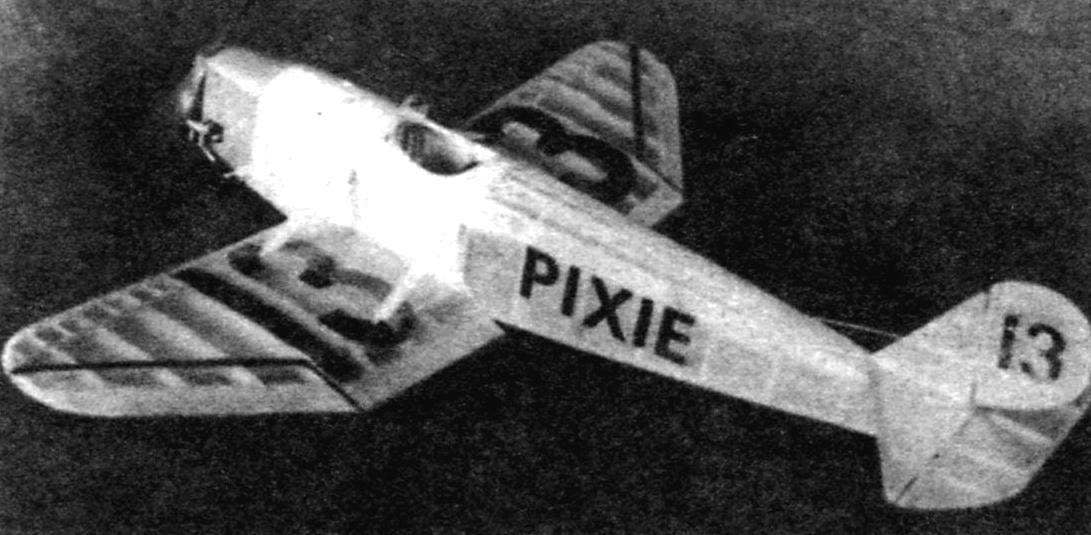
Model-a copy of the Parnall Pixie
The machine constituting the subject to be copied was created in 1923 by a small English firm, Parnall specialized then on light airplanes. In the framework of the research program of the enterprise constructed several variants of the Pixie. So, one of the first modifications had a wing of increased span of 8.4 m and a very weak engine power about 8 HP was Also implemented the project of high-speed micro-airplane with a much enhanced engine and wing length of just over 5 m. you Need to mention the double modification of this machine.
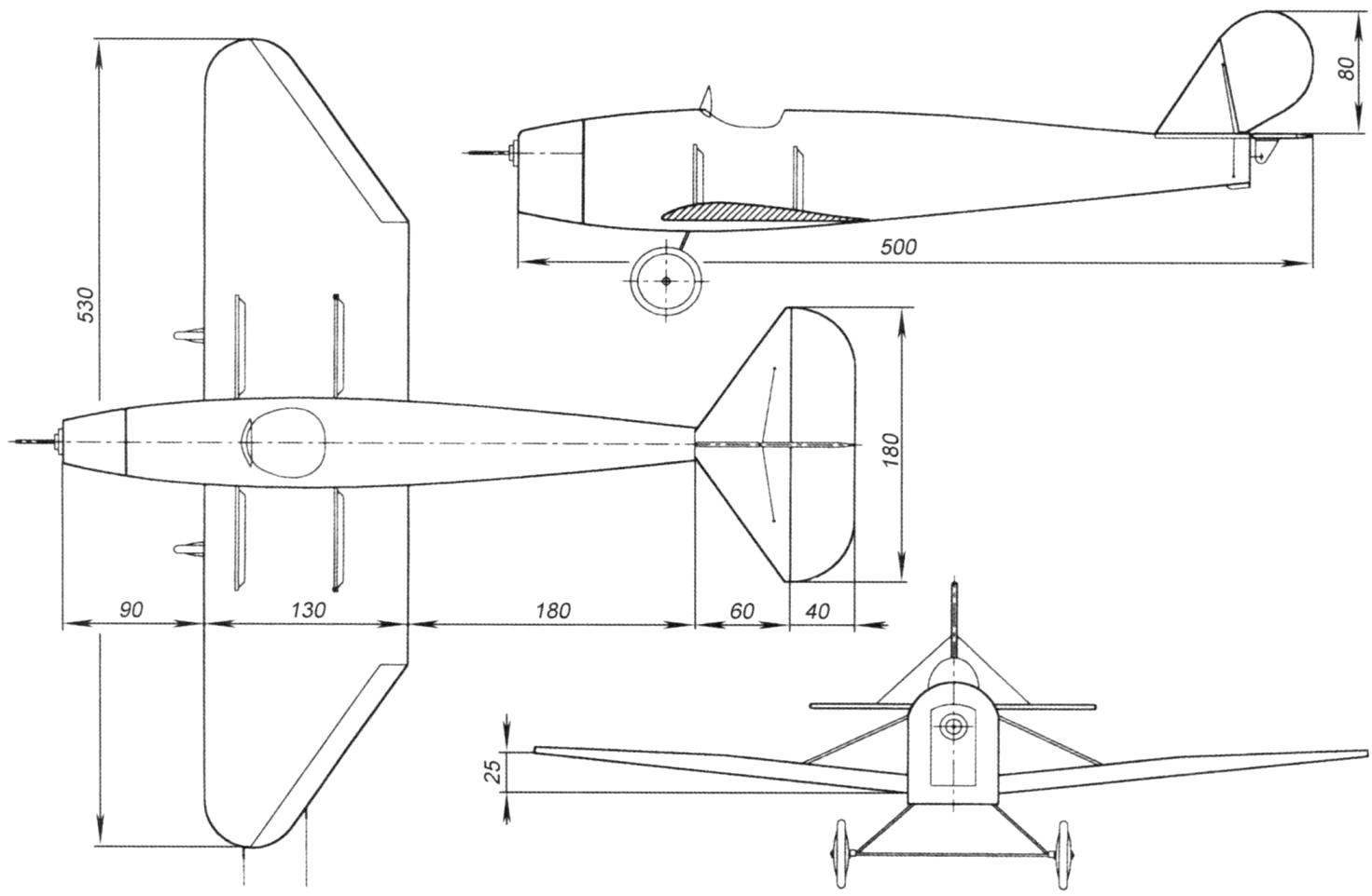
But the greatest success fell to the variant of the Pixie, who had averaged characteristics (that he selected the prototype for polyopia). Full length of the fuselage of this machine without node setup air screw is 5.2 m. the Wing span of 5.5 m is hung on the nodes at the bottom of the fuselage. Each of the consoles is supported by a pair of short struts, reaching to the upper longitudinal member of the fuselage truss. Short, stiff landing gear wheels are larger diameter. The basis of the plant – two-cylinder boxer engine capacity of 36 HP Maximum flight speed of 140 km/h. Very unusual proportions of the aircraft, which had a lengthened fuselage with the wide wing of small scale allow you to build an unusual, but effective model.
MODEL DESCRIPTION
The basis of the fuselage are two side of the farm, recruited on the flat bench of the balsa slats. Note that the assemblage of farms need to so that their external side facing down to the slipway. After gluing all of the joints of the front part of the farm is enhanced by plywood pads (they must be within the frame of the fuselage) running from the forward edge of the fuselage to the trailing edge of the wing. Recommend you to think carefully about their form, since the reading of the drawings it can be understood ambiguously. The pad must lie overlapping on all of the rails (its contours coincide with the outer contours of the side of the farm). Under cross-struts of the fuselage in the linings need to do cutouts.
After removal of the raised sidewalls of the stocks they are joined in a single farm the fuselage using alternately driven in place of the spacers. This operation is best done on a flat bench, placing it on the fuselage top surface down. While on the slipway needs to be applied to the projection of the fuselage (top view).
After Assembly of the frame, begin to its finalization. Primarily in the corners between the bottom longerons and plywood plates need to paste the balsa plate. Here you should also carefully understand the drawings on each side of these plates should be three pieces. They are placed close to the upright farms, and the upper edge of the same profile of the wing. In principle, the thickness of the plates should correspond to the cross section of the rails of the fuselage (4 mm). But since in this area the Board have a noticeable camber outwards, we recommend you to make the workpiece of thicker balsa veneer. After fitting the parts in place and dry they are sanded flush with the fuselage, forming a landing plane for mounting the wing panels.
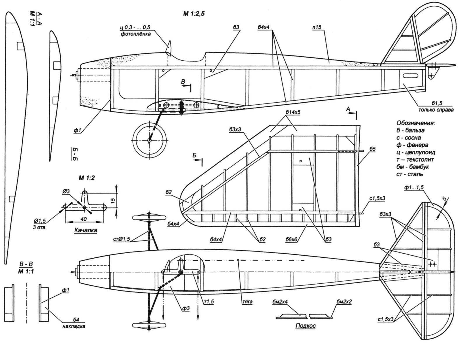
Now for the training landing gear from steel wire and are rocking the control of non-foiled fiberglass or Micarta. When these details are done, adjust the place in the fuselage horizontal power panel out of plywood with a thickness of 3 mm. the Front chassis is associated with a thread, passed through a series of drilled holes, and rocking placed on the axis, is made of screws with M3 nuts and washers. After the control of connectivity of nodes panel is glued in place. It remains to mount the lining to the output thrust of an Elevator to make the upper fairing of the fuselage from packaging foam. The latest in the form of the workpiece immediately bonded in place, while the final form is processed on the fuselage. In conclusion, it is necessary to mount a frontal frame of mm plywood. Installation of the plant is made later.
The wing is so simple in design that does not require special explanation. It should only be noted that the gusset plate strengthening fins placed at the lower plane of the wing, and minervarya panel for gluing the struts – at the top. The root ribs are glued consoles and processed according to the profile of pads of balsa wood with a thickness of 5 mm. Later they will allow to prepare the ends of the consoles in the form of a curved side of the fuselage and the angle of the “V” of the wing. By the way, only after this fit of the wing to the fuselage you can glue close to the side members of the mounting studs from the pine strips cross section 1. 5×3 mm. In the left console ribs and punctured holes for the wire cords, and in the ending glued a pair of plastic tubes to their exit.
The fixed part of the tail represent the simplest flat farm, recruited from the balsa rails of different sections. Handlebars has a feature. To obtain a sharp trailing edge, the boundary line runs from thin plywood. These items must fit in the corresponding notches in the ribs and edges of the rudders.
The next stage is the mutual adjustment of all main parts (fuselage, brackets, struts and rudder). Checking the connectivity again, you can get to the cording. As it can be use as a subtle signature termobloki and mcalenney paper. The foam fairing is pre-fitted by thin writing paper on PVA. In any case, keep in mind that the aircraft prototype was mostly white. On the sides of the fuselage starting at the rear edge of the wing, towards the tail was a large, black lettering PIXIE. On rudder both sides in black and the number 13. This number – and on the Central part of each of the consoles, with a font height equal to approximately 75% of the maximum chord of the wing. Landing gear was of the natural color of the metal. On the wing and, optionally, a thin black line to indicate the ailerons. They went from a broken trailing edge to the ending and had a chord corresponding to the rear sloping spar of the wing model. The visor of the cockpit is bent from your camera roll. The top edging on the prototype was not.
After finishing automated finishing model, need to deal with the engine. Here are no specific recommendations are not going to give because it all depends on your ability to find easy and powerful motor. Only advice – you need to find a motor with a capacity of at least 15 watts. The engine is placed in the foam nozzle of the fuselage, simulating the hood of this motor. The outer surface of the foam glued thick paper in PVA and painted with silver paint (on the plane, the prototype of the hood is bent of unpainted duralumin sheets).
Slat electric motor are connected with the contacts of rocking thick flexible wires. At this stage it is useful to put on the fuselage, all tail surfaces and to control the resultant alignment (wing because of their small relative weight of the adjustment will not give). It should be located in the area of the front wing spar or to be behind him at a distance of 5-8 mm. If necessary the nose or tail of the fuselage load.
Connecting cord wires to the gym can be performed in two ways. First, using a pair of electrical connectors, accessed via a removable hatch on the bottom surface of the fuselage. For wiring the electrical cord through the console it had to paste a couple of the guides Solomin. This option allows you to get rid of external connectors, usually located outside, near the wingtips. If this option is straightforward – use the normal when the console is placed immediately built-in leashes, firmly connected to the rocking chair, and connectors are installed outside.
It remains only to connect the wing to the fuselage. Carefully marked out on the fuselage to make room for studs already affixed to the ends of the consoles, run under them apertures. Using the pads by lining up the console is already nested struts relative to the fuselage, and all joints are poured with epoxy resin. If necessary, touch up the struts with white enamel, and their ends simulate under the small metal fittings with silver paint and black paint.
After selecting a propeller you can start overflights of the model.
The parameters of the current-carrying cord and power supply primarily depends on the engine and therefore not given here.
ARTAMONOV, head of the society, Saint-Petersburg
Recommend to read
 Model rocket boat
Missile boats are designed for application of sudden missile attacks on surface ships and transport ships on transportation on the sea lanes in the areas of fighting. It is small, with a... POTATOES IN DUTCH
The experience of potato growers says the Dutch technology of cultivation of root crops is the most efficient, and the work is minimal. And rows of clean, smooth, and the harvest...
