The connecting rod and both heads have pressed bronze bushings made with one hand (the external the motion model for annular track of the track) flange.
Spool is a curly polished plate of stainless steel with the thickness 0.4—0.5 mm. It is welded to the flange, the cone which is pressed by screw M3,5 to the knurled surface of the socket in the crank pin. When assembling the engine, make sure that between the spool and the end distribution wall there is a gap equal to 0.08—0.1 mm.
The piston pin is facilitated by drilling, peel plies are treated and polished. Material SHKH15.
The piston is extremely lightweight. Large recesses in the skirt are designed not only to reduce weight, to and for efficient cooling of the flow entering the crankcase fresh mixture. Threaded ring, lock insert with your finger and the rod, at the same time protects the finger from axial movement. Maximum relief piston group allows you to make centrifugal load longitudinal low, to increase the operating speed of the motor and to limit vibrations. Balancing is carried out by pressing on the cheek of the crank tubes of an alloy of VNM type. Piston material — al-26.
Casing from brass LS-62. The working surface (mirror) is chrome-plated and prichert. In steel, the shirt is inserted freely.
The head to reduce stresses in the sleeve are made navertyvajut on a shirt. Different from conventional designs are relatively powerful radial cooling fins and videobrasil grooves on the inner surface. Made on material of AK4-1T.
Fig. 5. The engine with axle and wheels:
1 — wheel with welded rubber and glued balsa bosses, 2 — gear, 3 — key, 4 — axle wheels, 5 — cheek 6 — intermediate gear 7 — a protracted bolt, 8 washer-screw, 9 — columnar shaft 10 — bearing wall, 11 — sealing ring 12 — shirt cylinder, 13 — cylinder, 14 — head engine, 15 — piston and connecting rod Assembly 16, the nozzle 17 distribution drive, 18 — pin, 19 — distribution wall, 20 — Carter, 21 — a protracted bolt, the 22 — plug 23 — spacer, 24 — supporting washer 25, the shoulder of the shock absorber.
Fig. 6. Dukhobory the engine with the crankshaft of the engine and a single-stage gearbox (flap valve suction mounted on the wall of the booster channel).
The drive axle is no different from the usual. Fork (30KHGSA) as easy as possible and has bronze bushings.
Bearings-axles — No. 1000098 (8X19). The same in the intermediate gear. Its axis, simultaneously serving as a finger attachment plugs, made of steel, the Assembly is pressed into the eyelet of the crankcase. Is on both sides of the slot under the locking bolts.
Gear made of steel 40X. Hardness after carburizing and Kalki 45НRС. Intermediate Z=40 and counter shaft Z = 45. Width of the crown in all cases is equal to 4.3 mm.
The drive wheels lightweight design, dural, devulcanizing rubber. The hubs are fastened with screws. Window relief cut and after balancing the wheels sealed the balsa plugs, which greatly reduces disturbances introduced into the ambient flow.
MODEL DESCRIPTION
Frame (tray) is milled from a block of duralumin (D16T). Has a relatively large compared to the size of the whole body height. This allows you to make it more hard and well to make a motor mount. When processing of the frame is particularly careful to the landing places of the plant: notch under the bearing wall and the hole for the pin junction of the wall. From the material of the pallet is machined and the intake to the carb. The gap between them to seal. This will ensure full use of the energy flow for a naturally aspirated engine. it is not so small — velocity head when the model of 300 km/h is equal to 0.04 ATM. Want to imagine what kind of pressure? Then try to clamp a hand outlet home vacuum — pressure there is the same.
Upper fairing (body) hollowed out of basswood and covered on all sides with Fiberglass 0.2 mm thickness for epoxy resin. Channel for supplying to the head of the motor cooling air is made of three layers of the same fiberglass on foam mandrel and glued into the body.
The front wheels of the knife-like shapes are made by conventional techniques. Their distinguishing feature is a small diameter and a sufficiently large distance between them. The first aerodynamically allows to correctly resolve the forward part of the model (the most important in relation to the flow) and reduce the weight of unsprung parts, although places high demands on the rubber. The second gives you the opportunity, strangely, to get rid of extra air resistance. The fact that closely spaced wheels, result in rotation of the entire annular layer of flow between the disks. The result is the same as if we put one nose wheel, but with the width of the treadmill equal to the distance between the discs.
Front axle — conventional pendulum-type plug with the machined sockets for bearings No. 1000095 (5X13). Careful selection of the material of the shock absorber. The size and elasticity of the rubber from which it is made, depends the whole bridge with different quality coatings kartodromo.
Tank with a volume of 80 cm3 soldered tin with a thickness of 0.4 mm. It is mounted on rubber pads, dramatically reducing foaming of the fuel. A stopping device operates on the principle of the latch, pressing the rubber feeding tube.
Shock absorber axle ordinary spring Tina. It is necessary to provide the ability to adjust the torque of the spring itself — this is useful when debugging “shell”.
Pay attention to two specific details. First, the air intake is located on the inner side of the model, and the exhaust channel of the resonance tube is bent in the outside. This is done in order to try to avoid running the course in a cocurrent stream of exhaust gases. After all, our “shell” is one and the same location in a matter of seconds! And getting exhaust gases into the intake can not be considered useful. The second — on the model of flywheel. The calculations showed that for normal operation is sufficient available rotating parts. So, if you are concerned about the low weight of this little micro-car, to improve traction with the track, use the extra load.
In conclusion, I would like to appeal to those who are not afraid to experiment. We want to offer the scheme with front-wheel drive. Using a horizontal motor with a split in the center of the wheel (or gently envelope them) resonant exhaust pipe, can dramatically improve the aerodynamics of the model. Compressed the front wheels closed bottom front wedge-shaped divider of the air, most of them located inside the body, and the protruding upper zakoptelova well streamlined “light” type aircraft. This allows you to make the area of the midsection is even less when a good elliptical sectional shape. Fully enclosed the wheels are to mix the incoming air, even their sides and create a vortex trail, which hides the entire tail section of the model, nullifying the effect of its shape on the magnitude of the total aerodynamic drag. But the creation of such a vortex tail takes considerable energy! If the wheels are closed and only a small part of them meets the incoming flow for its rectangular “heads”, it makes sense to do and licked the back of the body. By the way, this model has another advantage: it has no tendency to raise the nose, lifting the wheels from the track Assembly.
Certain interest and unusual power system using the most promising design of the crankshaft — two-post. The advantage of this motor — the volume of the crankcase can be reduced to the minimum that will provide the most rational form of the overflow channels. If you think that there is no need to make a longer connecting rod thus reduced in comparison with conventional motors side loading on the piston. Suction goes through the flap valve, ending in the cavity of the booster channel. In addition, with a slight increase in gauge, you can go to a single-stage cylindrical gearbox, fully using the advantage of such gears. Winning with the power of motor 3 HP compared to the bevel gearboxes will be almost a 0.1 HP! However, it does not dispense with the flywheel, since the mass and the number of rotating elements is small. However, it’s easy — just a cheek of the crank install ring, machined alloy type of VNM, and having a large specific gravity.
V. TIKHOMIROV, master of sports of the USSR

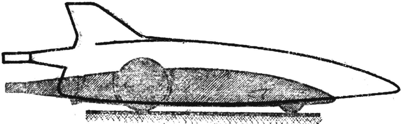 A lot of history in the fate of the car racing! Even now, when they are built almost the same pattern, in conversations the athletes to hear the terms “boat”, “drop”, “arrow”, meaning certain areas in the layout. Remember that was a “drop”. The name itself speaks about the shape of the hull. Aerodynamics have always maintained that the teardrop body has the lowest drag, to overcome which spent a large part of engine power. The advantage of “drop” and that it is well located for the centre of gravity of the car: it is very close to the drive wheels. This means that irregularities of the track model of this type will respond much less.