 To the editor of the magazine received a lot of letters in which modelers are asked to familiarize them with the device of the engine, designed by the Leningrad athlete E. Gusev. During 1970-1972 racing the car with this engine (cylinder volume up to 10 cm3) set five all-Union records.
Published drawings of the engine with a short description of individual components.
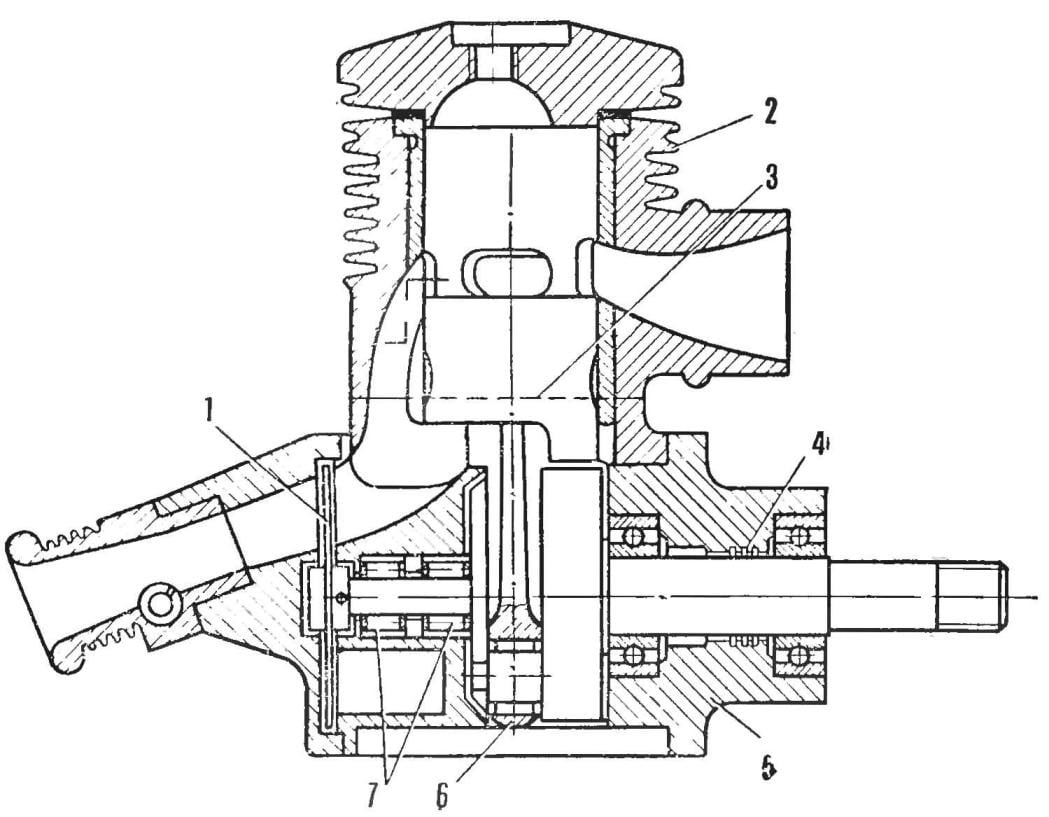
Engine “GEM-70” with three-way venting is designed to operate with a resonant tube has a cylinder diameter of 24 mm, a piston stroke of 22 mm, the displacement of 9.95 cm3. The engine crankcase consists of two parts: crankcase (lower part) and shirt of the cylinder. Across the shirt are four studs for mounting to the crankcase and the mounting of the cylinder head. Carter and the shirt is molded in a metal mold, and the venting and exhaust channels profiled in the casting, in the future, the purge channels do not require revision; the parting line of the crankcase and the shirt parts of the purge channels equally along the length.

Fig. 1. The engine Assembly:
1 — disc valve, 2 — shirt cylinder, 3 — line connector housing, 4 — labyrinth seal, 5 — toe crankshaft, 6 — needle bearing 7 — bearings.
Front and rear crankcase cover model, so the engine can be used for installation in car, air and boat.
The crankcase is cast from alloy AL-9.
Crankshaft made of alloy steel 12ХНЗА followed by heat treatment (cementation, or cyanidation). Shaft dynamically balanced, cheek shaft closes (swallowed) dural cap. Crank the neck has a Ø 7 mm, maximum main bearing journal diameter 10 mm. the Crank shaft is mounted in two ball bearings No. 1000900 (landing dimensions 10Х22 mm), and one of the bearings in internal size has a sliding fit: axial run after the installation of the flywheel 0.15—0.2 mm. For sealing the crankcase in the crankshaft wear made labyrinth grooves. The sock is made of alloy D-16 method
CASTING IN A METAL MOLD.
The slide cover consists of two parts — inner and outer, which profiled the suction channel, and in the space between them is a disk valve. It is made of steel sheet of thickness 0.3 mm and freely, with a gap of 0.05— 0.07 mm, rotates in the space between the parts of the cover. The drive of the spool from the crankshaft is carried out by the leash, mounted in two roller bearings. Between the latter there is an o-ring made of Teflon.
Rod, alloy steel, heat treated 12ХНЗА. The upper head has a bronze bushing, lower head— roller bearing, the rollers Ø1,5 mm, set in a steel cage. The lower end of connecting rod has an axial run-up of 0.18—0.20 mm.
The piston is made of special alloy of AL-26 by machining. Piston pin Ø 6 mm centered spring rings.

Fig. 2. Transverse and longitudinal sections of the sleeve:
1 — cross section a—A, 2 — vent window main channel, 3 — on the third (booster) channel.
Cylinder — brass LS-59, the inner surface of its porous chrome-plated chrome. The window on the sleeve are milled without additional sawing (Fig. 2). The outer surface of the sleeve prichert the hole of the shirt of the cylinder and is easy to install after heating to 200-250 shirt“. Cylinder head with an offset camera embedded in a sleeve for 2 mm and is secured with eight screws M3: four are the studs of the crankcase, four in the body of the shirt of the cylinder. The outer surface without fins.
Camshaft timing. Before the final layout of the Windows on the sleeve of their need to draw in accordance with the selected phases of the purge and release. The most successful phase, suitable for the configured and free exhaust: suction: beginning at 20° after BDC, the end is 48° after TDC duration — 208°, the purge: duration — 145°, III channel — 147“, exhaust: duration — 172°.
The engine with such valve timing works just fine without the resonance tube, and it easily enters in resonance, providing a significant capacity increase.
E. GUSEV, master of sports of the USSR, Leningrad


