At first, perhaps, to reorganize internally is still difficult. But guarantee, if it succeeds, then you will ironically look at classic patterned multi-element details of the expense of building a traditional, immediately aware of their unjustified pereprodannosti and illogic!
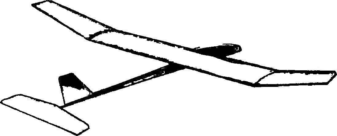
Svobodnaya model glider class A1:
1 — fuselage 2 — fuselage beam, 3 — keel, 4 — stabilizer, 5 — center section of the wing, 6 — “eye” of the wing.
So, try to embody the principle of “cutting off the excess” in the real model of the class A1. Let’s start with the wing as the main element determining the performance characteristics of microvarices. Take for case the maximum safely and… eliminate the spar itself (usually it represents a rather complex detail of the two shelves, buffs, walls, and kerchiefs). His role will be to perform leading edge, increased to unimaginable from the point of view of “Svobodnaya” dimensions — cross-section edges, planed pine, take equal 9X20 mm! Heavy item, which is pointless to compare with the balsa at all? Let’s break down the design work, and then go back to talking about the masses. Just note that all details of the profiled edge of the spar to center section and “ears” with the wood specific gravity of about 0.5 g/cm3 (although it is not so difficult to find pine or fir of high quality with a specific weight of 0.4—0.42 g/cm3 ) in the amount of not weigh more than 60 g (or 50 g with light wood).
Wing:
1 — force the leading edge-spar (pine-grained light-section 9X20 mm), 2 — pad (plywood 1.5 mm), 3 — extra spar (pine section OF 6 × 10 mm), 4 — the Central rib (lime, 12 mm thick), 5 — the intermediate rib (lip thickness: 2 mm), 6 — Klondike junction of the rib with the spar (plywood 3 mm punch in the rib), 7 — transient rib (lip thickness of 4 mm), 8 flange-spar “abalone” (pine-grained light-section 9X20 mm long, the wing end cross section reduced to 5X10 mm), 9 — ending scarf (plywood 1.5 mm, cut into edge and ending), 10 — ending (lip thickness of 5 mm), 11 — trailing edge (pine section 7H1,5…2 mm), 12 — plate rear edge (pine section 1,5X2 mm), 13 — Klondike edges (plywood 1.5 mm), 14 — front gusset (plywood 3mm).
The number of ribs cut in two or three times in comparison with the canons of the expense of building a traditional design and move on to a piece of basswood the thickness of 2 mm. Now they only need ten for the entire wing, and even two transitional and one Central, 12 mm thick. All the ribs in the amount of weigh together with endings ‘ 14 Add to list t-shaped edge with a mass of 6 g, and as a result, considering epoxy glue and small additional parts will be what a powerful frame of the wing without the covering Assembly has a weight of only 90 g in the twist of such a product is very hard, some elasticity in bending is in no way harmful, as when a powerful edge-longitudinal bending occurs without changes in the angles of the sections consoles!
Patterns for making wing ribs.
The wing turns out no heavier than balsa, clearly outperforming the latter as operational and prochnosti-zhestkosty characteristics. Unusual profile, after covering macalintal paper formed in mineralrich areas? Although a counter-question, and is not the answer, may I ask him: “You do not mind the profile obtained after covering the classic longerone wing given the painting of all longitudinal elements of the frame?” Because there is nothing to adjust not possible; in our case, due to the modification of the contour of the rib on average, obtained any desired profile, but still very precisely defined in most demanding area of the leading edge.
Well, it’s hard to move to a new design psychology? If special difficulties have arisen, let’s stabilizer. First of all look at the drawings and understand the scheme of the horizontal tail. Now we give the masses of individual elements: pine front edge — 3.5 grams, trailing edge after profiling for a ready stabilizer up to 2 g, of fake parts cross set — about 3 g in total in the thickness profile of about 6-7 mm. total 10 g maximum — and that after Assembly, the epoxy resin and viskazivaniya frame. The cording is performed from a thin Mylar film, glue only at the ends of the frame and the ribs (by the way, with film covering was specified a profile with a real thickness; under conditions more hard paper covering can be laid flat profile 3 mm thick).
Stabilizer:
1 — ending (lip thickness of 3 mm), 2 — leading edge-spar (pine grained section 3X12 mm, to the ends of the stabilizer of cross-section reduced to 3X4 mm), 3 — rib (lip 1.2 mm thick), 4 — the Central rib (lip 6 mm to the trailing edge to narrow up to 3 mm), 5 — trailing edge (pine, harvesting a section of 4X4 mm after mounting on an edge section height be reduced to 3 mm and rounded back).
With a keel — even easier. If you use the hard aluminum wire (or aluminum knitting needles) Ø 2 mm and note that the weight of this edge equal to the mass of solid balsa keel, cut from a plate thickness of 2 mm after double-sided stitched ready element of the film becomes clear: this is better as balsa by weight (solid wood in fact, after finishing the paper emalita will be twice as heavy!), and strength. By the way, now you do not need for readjustment cut out the steering surface, do it for articulated suspension and fixation system of the steering wheel in place — new keel wire can be slightly podsokratit, and further to correct the tension of the film covering.
It remains to design in the style of the entire model and its fuselage. I think it is enough to say that the mass of pine slats with a length of 600 mm and a cross section of 10X12 mm, ostrogannoj by the end of 5X6 mm, equal to 18 g, as the rest will become clear. If you are interested in the case, compare the mass of these beams and classic, assembled from balsa and pine. Only one condition: to compare the weight of the blanks and completely finished decorated beams!
Fuselage Assembly:
1 — metal download (put both sides on the screw M3), 2 — bow section (basswood or plywood 10 mm thick), 3 — wing box (plywood 2.5 — 3 mm, ellipse size 15X50 mm), 4 — pin M3 fixing wing (wire OVS), 5 — pin additional M2 (wire OVS), 6 — coupler junction of the beams and the bow (thin nylon yarn with resin), 7 — tail boom (pine-grained light section of 10X12 mm to the tail section to reduce to 4X6 mm), 8 — of the root rib of the keel (lip 3-4 mm thick), 9 — the contour of the keel (hard aluminum wire or needle Ø 2 mm), 10 — keel to protect the rubber mounting stabilizer and wicking devices (lime 2 mm thick), 11 — box stabilizer (plywood 1.5 mm and the rake cross-section of 1,5X1,5 mm), 12 “patch” fixing the stabilizer angle of attack, 13 — hook wick (OVS wire Ø 0,8 mm), 14 — pin M2,5 mounting the tow hook, 15 — landing ski (bamboo or plywood to put under the bow of lime). On the “B” stabilizer conventionally not shown.
The forward part is generally self-explanatory, just pay attention to the location of the balancing weight consisting of two halves which rasp as needed. And mentally compare this system with the usual case in the bow, which have to enter the plywood sheathing to do the “stopper” to think about how to fix the fraction in the pencil case or make up for resin casting…
Powerful power circuit of the new model of the glider allowed to take the risk and mount the wing on the fuselage tightly. The meaning of such a technique that, once debugged, the model will never change the characteristics due to random displacement of the attached wing.
In addition, the new glider is much easier to manufacture, any features in the technology and debugging it has not. Due to the small number of joints as the adhesive when the Assembly is used exclusively plasticized epoxy (it also increases the reliability of the loaded nodes). The principal balance settings indicated on the drawings. After applying the paper covering and painting the wing is held in the stocks during the month. On the left “ear” is given a negative twist (4 mm at the trailing edge), the right half of the wing is twisted to plus 2 mm. To 8 mm from the leading edge across the span is glued to the baffle thread Ø 0,5 mm. Tow hook side type — in this power scheme of the airframe it enables an effective and powerful dinamalar.
A. DMITROV, the head of the circle
Recommend to read GREEN “HAIR” These guys have a lot in common. They all live in the Serpukhov district, their parents — farmers. But most importantly — they are all involved in the circle of technical creativity of... NO WORSE THAN DIAMOND The glass cutters with carbide rollers are widely used by home craftsmen. But those who work with glass often still prefer the diamond. And it's not just more sharpness and hardness of...