The second factor is dynamic stability — longitudinal component. How important it becomes clear from the fact that most of the world’s leading athletes use the airboat flexible shafts to align the axis of the screw to the horizontal position. But such a system is able to “eat” up to 30% of the power plant! But modelers did it, knowing that is not yet designed corner joints that meet the conditions of installation of the node in the flow front of the screw, and not knowing the other circuits.
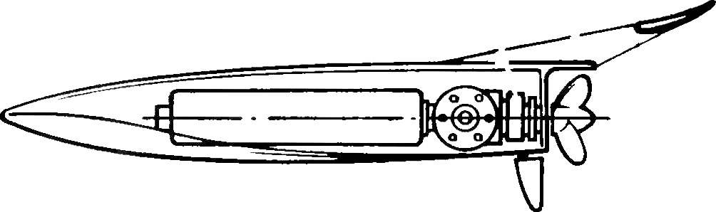
As soon “kill two birds with one stone”, it will become clear when considering the scheme of the new model. Its advantages not only in a sharp decrease in dimensions and thus mass. At the same time has managed to facilitate power system as a whole, to dramatically increase the efficiency of mechanical transmission, to simplify all of the actuators and thus to achieve a horizontal position of the axis of the screw. Also, now (and only now!) you can talk about an accurate reflection of the mode of operation of the propeller, which became the “cyberterrorism”. Earlier the slightest excitement on the waters led to the mover in such uncertain, instantly changing conditions, optimization has become simply meaningless; the method of selection was able to find only options that are more or less forced to meet the reduced requirements.
So — a new offer modelers the scheme of velocity model better than any known alternatives. Remains to try it in. Of course, you will have to devote to practicing her lines a certain time. But as they say, it’s worth it. The sharp increase of speed and dynamic properties is not all the advantages of the new scheme. Significant reduction in effort as the power plant and microcarpus allows to conduct a wide search in the field of hydrodynamics of the glider.
And what are the prospects of the proposed scheme? It turns out that from this point of view, it is more advantageously known. Take a look at the drawings. And try wisowaty in this model twin-engine installation with counter-rotating propellers. Two engines are the heads from the axis of the body, synchronization of propeller shafts can be either simple gear connection (which is calculated only on the efforts of the synchronization, much less than the effort the immediate transfer of power to a single engine!), or a light clutch. In addition to achieving ideal lateral stability of the glider, such a solution is interesting from the point of view of lifting maximum power with less cubic capacity depth force can be increased. And the problem of noise by dividing the allowable displacement is solved much easier.
Another interesting factor that you can encounter when creating ultra-small lightweight models — the need to ensure that the correct aerodynamics. In particular, it relates to the hull form, as airboat new type of load per unit area of the projection of the body “in terms of” a lot less, but the potential for rapidity more. It is possible that in the ship modeling questions of aerodynamics can come out on top and be faced with the problems of hydrodynamics. And then you can help graphs showing what criteria to use when selecting stabilizers and rear wings. As it seems like the device is unusual today, it will become necessary for the models of tomorrow.
Finally, I would like to offer another promising solution; it can even be used on regular RC today. This is to introduce into the transmission after the flywheel of the engine and the clutch. The event will be clear, if you carefully to understand what is happening with the engine and model when entering and cornering and why models with electric motors are at least not inferior to gliders with engines of internal combustion.
Before entering into the rotation somehow we have to reset the speed of any model. On the ice this is done by controlling the carb. However, small-scale mining operations schema inherent major disadvantage: at lower rpm the engine is out of the resonant mode exhaust, and dramatically drops the power some time continuing to go with a small deceleration due to the significant energy stored in the high-speed flywheel. Considerable energy has and heavy the model is that, despite the potential of the engine to dramatically reduce the power, forcing you to start preparing for your turn much earlier. But here’s the twist, here it is finally passed. Now what? Would need to dramatically increase speed. But… you don’t! The engine, derived from the resonant mode, in any action with the carburetor low power, but still in front of him, but the acceleration of the heavy models, the aim is to disperse inhibited the flywheel? What kind of dynamics…
We have the athletes to reluctantly transfer all the parameters of the model and the plant with maximum values at intermediate, not so distant from the terms of cornering. Though not as fast, but a little more dynamic. And that’s not excluded when the acceleration will be delayed so much that, unable to finish, will have to go to a new braking before the next turn. Another compromise… have not bothered to look for them?
And the output — the same relief the entire model, increasing the efficiency of the plant as a whole and… in the application of the clutch. Only it will allow the glider with the engine not only closer in dynamics to the “train”, but maybe even surpass them. The meaning of the introduction of the coupling here. Before turning clutch, until then, recorded a little bit is released (degree of raspisanii easily adjustable or can be controlled). The model, especially lightweight, quickly slows down, because the energy is already hyped the flywheel is not transmitted to the screw fully. But the flywheel starts to gain momentum and energy as we took some of the load from the engine. The motor goes to theresonance momentum. So, after cornering it is already prepared to deliver maximum power. Just need… to slow down his clutch. Too abruptly to do this will fail in a huge flywheel stored energy at the end of the turn directly running the dispersal model. And after the exhaustion of the excess energy perekrestnogo flywheel engine with high rpm shifts at resonance. Immediately!
The dependence of velocity on distance for different model types:
1 — optimized model with a reduced maximum speed and satisfactory performance of the braking-acceleration, 2 — a similar model, adjusted only for the maximum speed and have consequently degraded dynamic performance, 3 — model with the same motor dimensions and power density.
The dependence of velocity on distance for models with internal combustion engines:
1 — corresponds to the previous schedule, 2 — model is reduced and light weight, the propulsion system is optimised for the new conditions 3 — similar to 2 mu, but in the scheme used the clutch.
Perhaps such a system will require either a separate control carb and clutch, or their joint work, in which the thrust of the carburetor begins to move after poluraspredelenia clutch. Here, the experiment is easy to carry. It is important when choosing a clutch design to allow smooth switching. One of the possible variants shown in the figures. It is designed on a proprietary brakes for model aircrafts, according to their passport data and constructed graph of brake torque. In the drawings the clutch is shown as a separate node, however, there is a direct sense to combine the clutch with the flywheel of the engine. In the proposed embodiment, the clutch is able to hold only part of the torque, since motor 3.5 cm3 the time comes to 3000-4000 g*cm, the Desired friction is achieved by installing multiple drives on the slave leash of the shaft and counter-elements on the spines of the clutch housing. There are other options of clutches (centrifugal, such as those that are radio-controlled car, or classic friction multi disc), mechanically operated from a conventional rulemaking with the introduction of the thrust of the spring elements to control the brake torque. However, the electro-shaped piece much more attractive as it does not require the use of rulemaking, thereby achieving the simplification of the scheme with a corresponding increase in reliability, and simplification of the model. Of course, unlike aviation brake clutch should consume energy only when raspisanii.
Brake coupler and its characteristics:
1 — the leading shaft, 2 — current-carrying rings for the power winding of the electromagnet, 3 — clutch housing (mild steel, a wall for all parts not less than 2 mm), 4 — coil magnet (wire of PEL of 0.3 and to fill the coil form; winding resistance of about 6.5 Ohms, after checking to impregnate epoxy resin), 5 — spring, 6 — brake disc (a soft steel thickness of 2 mm), 7 — the driven element with a finger-leash within the window brake discs, 8 — ball bearings.
So considered interesting prospects for the development of a radio-controlled speed boats. Maybe not all the design findings will find application in the models of tomorrow. However, when developing new devices, before you reject the proposed solution, we encourage you again to read this article. And, most importantly, to try to distract from the fascinating influence of the usual supertehniki that use of very scarce materials and technologies based on “frontal” methods of speeding up reliable development. And suddenly everything is much simpler!
And last, think, and weigh again — whether or not to engage in such microglossary simplified Moto installations today to tomorrow with the “armored” made from supermaterials and equipped with powerful engines, not to be behind! Maybe the future for the public in the construction of microglossinae!
V. VIKTOROV, engineer-hydrodynamic

 Today we offer modelers an unusual material. If the majority of the publications was based on existing research and was devoted to the already realized results of the design search, then this article is for reservoir engineer V. Viktorova, as if in contrast to them, entirely composed of mere “ideas.” But how many times history of modeling, and technology in General, proved the viability and the viability at first seem “crazy”. Characteristically, they at first met with either resistance on the part of even the most experienced athletes (perhaps I ought to say not “even” but “especially”? After extensive experience of the wealth, but sometimes the “limiter” for anything that does not fit into the framework of experience), or complete disregard.