Not so long ago in the journal “modelist-Konstruktor” was about the simplest model of a glider made from a conventional packaging corrugated Board material although not aeromodelling, but it is durable, tough and light. By the way, a square meter of corrugated Board with a thickness of 3 mm has a weight of only 400 g, respectively, the density of this material is only 0.13 g/cm3! Experiments have shown that the durable and lightweight corrugated cardboard is well suited for creating flying models. Needed only in the cutting and processing of corrugated Board to consider some of its features and to use a knife-cutter, literally honed to razor sharpness, otherwise cut lines get ragged.
In the design and fabrication of simple models has developed some specific design techniques for working with cardboard. So, it was found that a sufficiently high rigidity of this material allows to create a spatial model elements with virtually no internal set. In particular, the fuselage and wings after gluing acquired sufficient strength and rigidity as to bending and torsion.
The corrugated Board has one more feature, due to its cellular structure, is the complexity of the dock cut-out panels. However, in the process of creating models for this purpose was developed a fairly simple way. It consists in the pre-trim the ends of these panels tiny channels made of thick drawing paper. First, the workpiece carefully marked pattern of this channel for corrugated cardboard, thickness: 3 mm overall band width is 9 mm, the width of the shelves profile at 3 mm. Next with a sharp knife-joint are shallow (approximately on half of thickness of paper) cuts on the two inner lines of the pattern, and only then from a sheet of paper is cut with a 9-mm strip and is bent at the cuts in the form of steel channel.
Further, the end of the panel and the inside of the “channel” promazyvaetsya glue — mounting “liquid nails” or stationery PVA glue, then trim until the glue is fixed on the end of the panel normal office pins. The finished panels fit together, the same adhesive connection is obtained quite durable.
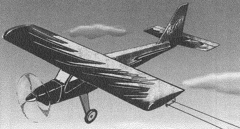
So, we present you another, this time more sophisticated aircraft made almost entirely of corrugated cardboard. This control line model plane engine KMD-2,5, which is a high-wing monoplane with the classical scheme with straight wings.
Geometry cord model airplane engine KMD-2,5.
The layout of the model:
1 — propeller, Ø 190 mm; 2 — engine KMD-2,5; 3 — fastening the engine to Motorama (screws and nuts M3 — 4 in kompl.); 4 — engine hood (Vileika of fiberglass and epoxy resin); 5, 8 — attaching the wing to the fuselage (M3 screws); 6 — wing; 7 — fuel tank capacity 70 ml; 9 — the top panel of the fuselage (cardboard); 10 — side panel of the fuselage (cardboard); 11 Kil (OCC); 12 — skid (steel wire Ø 2.5); 13 — tail boss (Linden); 14 — lower panel of the fuselage (cardboard); 15—rear support wing (Linden); 16—engine mount (plywood s10); 17—base of the chassis (Linden); 18—spring chassis (aluminum, sheet s2,5); 19—a gear wheel ø40mm; 20—connecting tube of the engine (silicone rubber); 21—front support wing (Linden); 22—rocking the Elevator control (duralumin, sheet s2,5); 23—self-tapping screw Ø 3 with two washers; 24—stabilizer (corrugated cardboard); 25 loop—”eight” of nylon yarn; 26—the Elevator (corrugated Board); 27—mount chassis (bolt M3 nut).
The fuselage model consists of two corrugated sidewalls, top and bottom panels, and engine mounts out of 10 mm plywood. In addition to these basic parts for the fuselage will also need front and rear support of the wing and the chassis base, carved from basswood. Made from basswood and the rear boss of the fuselage.
Fabrication of the fuselage begins with the preparation of panels of corrugated cardboard sides, top and bottom. However, note that the side panels should be exactly the same — this can be achieved, if after marking the outline panel on the sheet of corrugated cardboard to move with the needle coordinates of its corners to another sheet.
As mentioned above, cutting the corrugated Board should be razor-sharp knife-joint using a ruler. Pre-workout — the knife should be oriented so that the cut plane is perpendicular to the plane of the sheet, and slitting the corrugated Board should be two or three sliding movements of the knife. If in the plane of the cut will be ragged corrugations or “noodles” from multiple strokes with the knife, it will mean that the work is done right.
After harvesting of fuselage panels needed to turn over them the ends of the “u”, bent from strips of drawing paper, as has already been described above.
When assembling the fuselage, it should be borne in mind that the front and rear support wing and the base of the chassis are fixed by glue in the slots of the sidewalls. At first, these wooden parts (including engine mount) is mounted on one of the sidewalls and then to the place pristykovyvayas the second side panel. At the end of Assembly work are glued top and bottom panels. To ensure Squareness of panels of the fuselage until the adhesive has cured, it is recommended to keep it in its simplest device — the same used previously for the trim panels.
Tail feathers are made from corrugated cardboard. Billet fin and stabilizer cushions are covered with paper profiles — shown in our drawings. Edging for front edges it is best to bend and cut using the fit — plywood strips 3 mm long with a rounded edge. Trim the back edges of the keel and the rudder is bent in half a strip of drawing paper; the other paper edges and fringes “channels”.
Linkage of the Elevator on the horizontal tail is made with loops-eights of the nylon thread.
The wing is straight, with PLANO-convex profile, its relative thickness is 13.3 percent (20 mm). The use of corrugated cardboard allows you to implement beznervyurnaya scheme of the wing — shaped profile is supported by only two end and two Central ribs at the point of joining the wing and fuselage. If necessary, you can install one corrugated rib in the middle of each wing.
Wing:
1—root rib (corrugated cardboard); 2—rear docking port wing (lip); 3—trailing edge (pine); 4 — the bottom wing panel (corrugated Board); 5—zakonov-ka (fine-pored foam plastic); 6 end rib (corrugated cardboard); 7—front edge (pine); 8 — upper wing panel (corrugated cardboard); 9—front docking port wing (Linden); 10—base rocking administration (Lipa).
The jointing of panels of corrugated cardboard, decorated with paper “channels” (the numbers show the sequence of Assembly).
Diagram of the trim the front edges of the fin and stabilizer and trailing edges of keel and rudder.
Blank “channels” from the drawing paper to outline the panels from corrugated cardboard.
The scheme of mounting of the Elevator with loops-eights of nylon yarn (A—stabilizer and Elevator made of corrugated cardboard; B—formation of loops with a needle and nylon thread;—ready loop).
The sequence of manufacturing of corrugated wing panels:
And, a corrugated cardboard blank top panel of the wing with a banded front edge; B—top panel from sagging along the corrugations of the grooves; In—ready wing.
Elevator drive:
1—bezel made of paper “channel”; 2—a washer of stiff paper; a 3—M2 nut (2 PCs.) fixing the horn on the steering wheel height; 4—bushing (Linden); 5—pylon (steel, wire Ø 2); 6 — M2 nut fixing thrust management (2); 7—pull Elevator control (made of anodized aluminum Ø 3); 8—wheel height.
The upper panel of the wing must be convex, and to make it so, along the front inner part of corrugated cardboard blanks, smooth plastic rod (e.g., a handle from a toothbrush), you need to push multiple parallel grooves, placing them between adjacent corrugations. The thus prepared blank is easily bent in the intended places. Finally, panel enclosed paper channels. Wooden embedded parts (the connecting nodes and the base of the rocking control) are first fixed with glue in the slots on the lower wing panels; adhesive fixed on the bottom panel, and ribs. Near the end rib of the right (outer) wing lead is assigned a weight of 25 g. Further, the ribs and the fixings promazyvaetsya with glue, and the thus-prepared lower the top panel is covered, then the resulting “sandwich” is drawn stationery rubber bands to a flat, smooth Board to complete the curing of the adhesive. It remains to secure the front and rear edge of the pine slats and the wing is ready.
Chassis model — spring type, the spring is made of sheet duralumin with a thickness of 2.5 mm. Wheels — plastic, rubber (children’s toys), with a diameter of 40 mm, on springs they are mounted with M3 bolts and nuts.
Rocking control also dural from strips with a thickness of 2 mm. control rod made of duralumin knitting needles 3 mm in diameter — its ends flattened and drilled holes with a diameter of 2.2 mm.
Pylon rudder is made of cut steel wire with a diameter of 2 mm, bent in the form of the letter “G” on the horizontal and vertical parts of which is threaded M2. To install the horn on the steering wheel in the last pasted a fake sleeve with a diameter of 10 mm with an axial 2-mm hole; mount the horn to the steering wheel is two nuts, locking nuts from loosening — a drop of nitro.
The engine closes the hood, laminated of fiberglass and epoxy on the foam disc. The shell wasn’t glued to the foam blank before work is isolated hyperfine cling film.
Fuel tank capacity of about 70 mm soldered tinplate with a thickness of 0.3 mm. Into the tank soldered three copper piping filling, drainage and supply pipe of the engine. Note that the finished tank must be installed in the engine mount before gluing it into the fuselage.
Be aware that cardboard is highly hygroscopic, so after assembling the wing and fuselage should be painted with two layers of enamel.
The model is made of corrugated cardboard, it came out light and fly. I must say that the significant stiffness of this light material often leads to breakage of the wing or tail on hard landings. Probably the next models will have to change the method of mounting the wing to the fuselage — not fix it with screws and rubber rings on wooden pins.
I. MNEVNIKI
Recommend to read SECURE ATTACHMENT In search of reserves of living space and additional features of the interior, our attention is increasingly attracting ceiling: more and more decisions related to trillenium and slabs.... MASCHLANKA As the camouflage makes the scout invisible on the ground, so maschlanka hide from the eyes of the rough risers of steam heating, giving the room or the kitchen a more cozy feel. Hide so... Scroll back to top
 Not so long ago in the journal “modelist-Konstruktor” was about the simplest model of a glider made from a conventional packaging corrugated Board material although not aeromodelling, but it is durable, tough and light. By the way, a square meter of corrugated Board with a thickness of 3 mm has a weight of only 400 g, respectively, the density of this material is only 0.13 g/cm3! Experiments have shown that the durable and lightweight corrugated cardboard is well suited for creating flying models. Needed only in the cutting and processing of corrugated Board to consider some of its features and to use a knife-cutter, literally honed to razor sharpness, otherwise cut lines get ragged.