
 In recent years avtomodelisty closely watching the development of a new direction for technical activities and sports design of high-speed radio controlled model with internal combustion engine. At first they were built by high-class athletes, but now a lot of successful and budding. What are the athletic requirements for these models, and some technical data have model classes f-I and f-II?
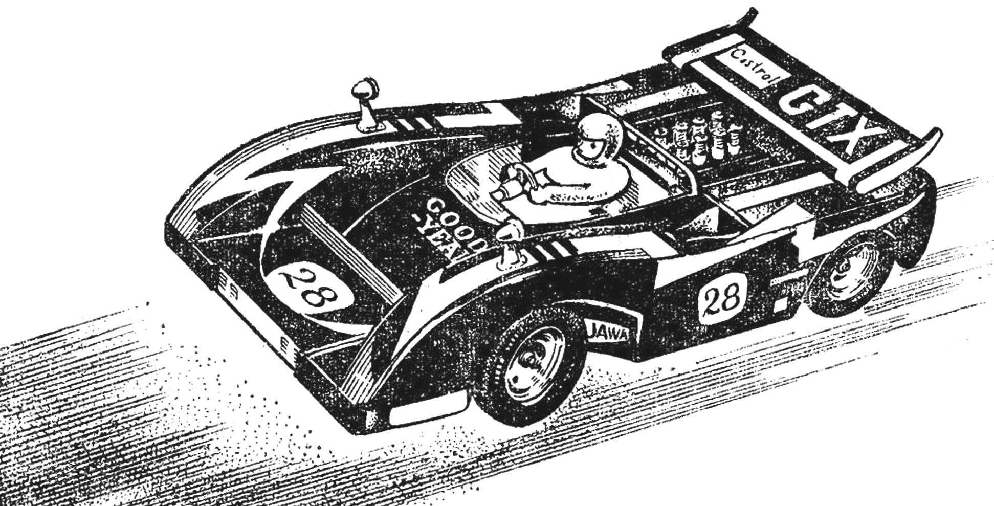
Technical requirements. The model class f-I are copies of cars “the formula” open wheel f-II — copy of the sports car “Grand tourism” (“GT”) with closed wheels. The body of both classes of models is only performed at the scale of 1 : 8 and on the forms must match the shape of the prototype. On the model set one or more motors with a total working volume of 3.5 cm3. The weight is not limited. Modern models it is in the range of from 2.5 to 4.5 kg. the deviation of the dimensions from the scale is within ±5% for length, height, wheels. On the model binding of the clutch and the brake. The clutch can be automatic and driven by a servomechanism. The brake shall hold the model at the start and to possess sufficient reliability. The capacity of the fuel tank (along with a feeding tube) is not more than 125 cm3. The engine silencer is supplied with a volume less than 20 cm3; the exhaust pipe must be directed at an angle not less than 10° sideways or up relative to the exhaust channel of the engine. Desirable install oil pan (a container for collecting waste oil), the amount of which is included in the measurement of the volume of the exhaust pipe. The size of the latter may not exceed 56 mm2 (tube with inner Ø 8 mm). All this is done to ensure that the noise from the engine measured at a distance of seven meters on the level and in the direction of the exhaust pipe, does not exceed 80 dB. In the body type model “GT” square openings for entry of cooling air jets may not exceed 100 cm2. On the model class f-1 provides the implementation of the figure of the driver arms and steering segment. The models of these classes is not included in the assessment of quality workmanship, exterior and completeness of details. The rules provide only a neat color and aesthetically pleasing model. However, these factors bring the model to the prototype and play a crucial role in the choice of viewers and fans of “your” car during the competition.
Further, the rules limit the main dimensions of the model, they should not exceed (in millimeters): base — 300±10%, width — 270 (including wings or spoiler), height 200 (no wing), length — 610 (without exhaust pipe), front wheel diameter — 78, rear — 90, the width of the wheels front — 50 rear 90, the width of the wing — 270, depth — 100, the installation angle is 35°.
When the backup car prototype in scale 1 : 8 there is a need for deviation from these parameters, the designer must confirm that documentary evidence.
At the technical inspection before the competition it is necessary to submit drawings of the car prototype published in any journal, or copies of these drawings from magazines. Without this, the model is not allowed to compete. (Permission for use of the transmitter also need to bring.)
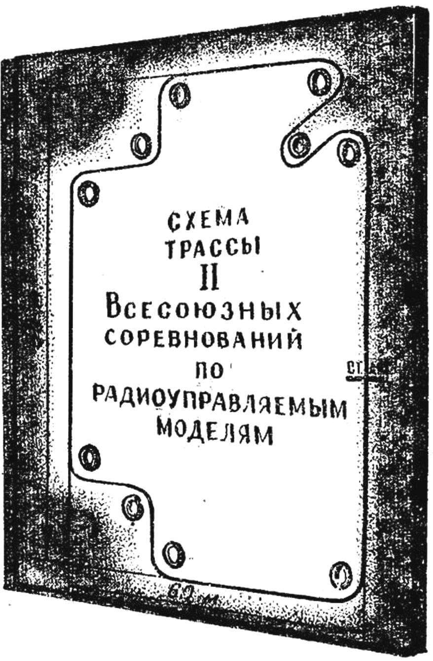
From the body of the model there may be a needle adjustment, carburetor, cylinder head with cooling fins, the lower part of the flywheel and gear reducer. Mounting screws and nuts must not exceed the width of the rubber. Models may only be used in multi-channel proportional radio system with replaceable crystals, because during the competition will start several (up to 6) models, and the race is on a level paved area on a difficult track with many twists and turns. The size of the track can reach 60X80 m.
Track and starts. During the race the athlete has no right to leave the workplace and touch the model. Releases model from the start and maintains it during the competition mechanic. Typically, the functionality mechanic performs someone of the team members.
The margin of safety for individual components and parts in the models should be significantly higher than that of the prototypes. During the competition the models develop speed up to 60 km/h. Choose a platform of large size with perfectly smooth tarmac is virtually impossible. Consequently, small bumps, cracks will be required. When you hit the wheels at that speed in a crack, or if you hit a rock with a height of 1.5— 2 cm and there is a huge load on the entire suspension model. On the turns, even at speeds of 15 — 30 km/h when models collide (and it happens, when one of the athletes made a mistake and he has to return the model to the right to pass rotation), the relative speed increase to 30 — 60 km/h, and this is a very serious test for the model. And in such situations does not help, as a rule, even protective bumpers (usually a loop of wire OVS Ø 2 — 3 mm), which use some athletes. Sometimes they cut the bolts, ruining the hood even more, are folded under the body and do not allow models to move forward. It also happens that models are flipped after hitting the barrier. In this case, it is important to not have damaged any of the power supply system of the engine or control models. It should also be noted that the track is not the track: it can be the sand and puddles. The first affects the bearings and gears, and the second on the operation of radio equipment, which does not tolerate moisture. The attachment of the device it is necessary to pay particular attention to: this is the most expensive that is on the model. The design model can complicate the individual nodes and details only if I am confident that together with the improvement of the dynamic characteristics of the node and the model as a whole won’t lose in reliability.
A good test for the already assembled model is to test it under conditions more rigid than the competition. Muscovites, for example, tested the model in March (when it is not the snow melted), in the rain, through mud, over uneven pavement — and all at extreme speeds. Needless to say, the difficulties in conducting such training, with only on subsequent rinse and clean model takes 1.5—2 hours. However, the result is obvious: the model, going all the championship, never let your designers. The time required for the construction and debugging of models of this class, is different and depends on the training of the designer, availability of reference material, from the material-technical base of the sports club, which operates the athlete. Typically, the construction will take 1 — 2 years.
Where to start building the model and in what sequence to produce it? Consider these and other issues on the example of the construction of models of formula f-II “McLaren M-8”. One of the important stages of construction of the model is the correct choice of prototype. There are many very elegant, light and elegant cars first formula (open wheel) that I began to admire the first saw. However, it is easy to make sure to squeeze equipment, engine, tank, muffler and the entire suspension into a small space under the hood pretty hard. In models with closed wheels the space under the hood about 2-3 times more and therefore are much easier to place all the details.
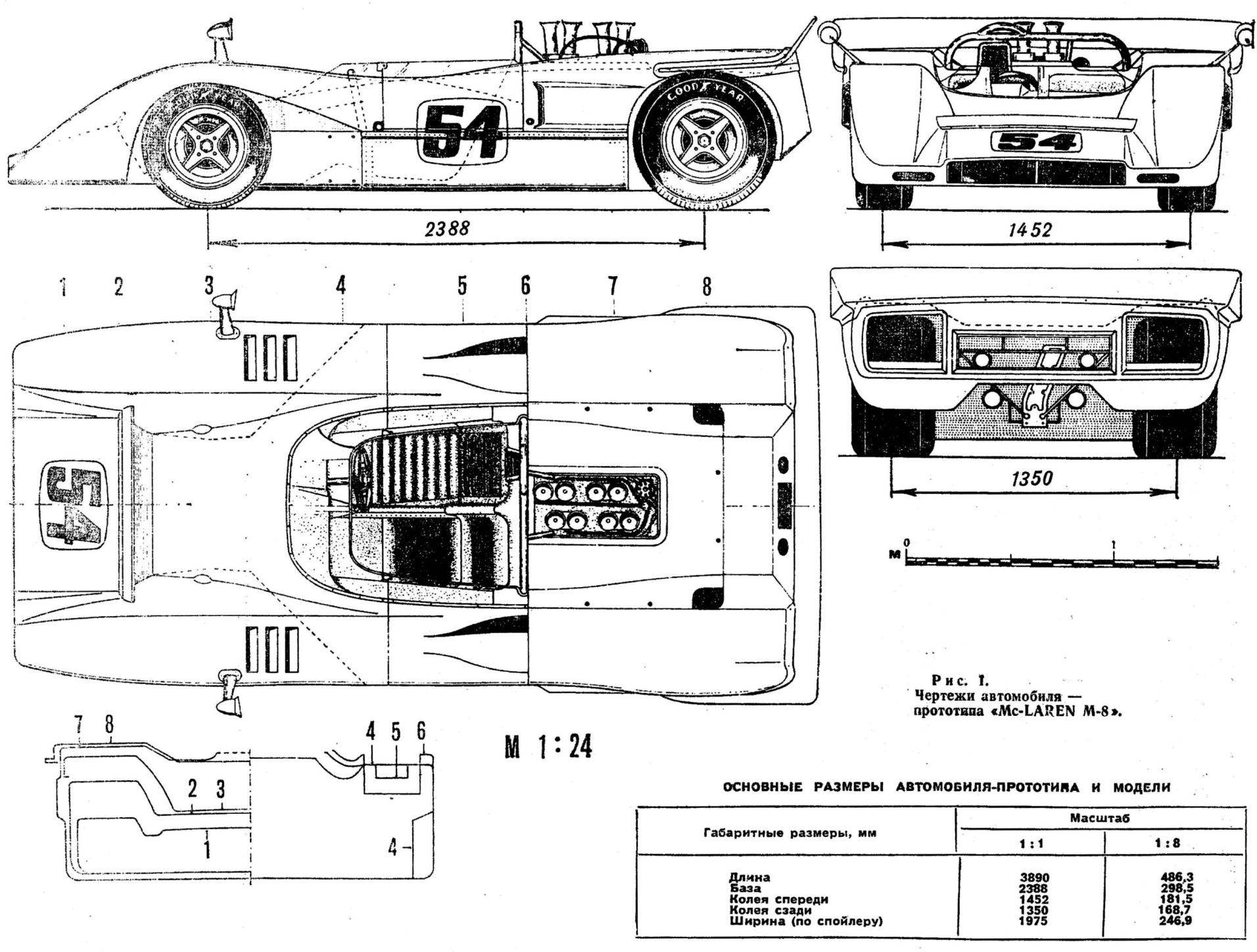
Fig. 1. Car drawings — prototype “McLaren M-8”.
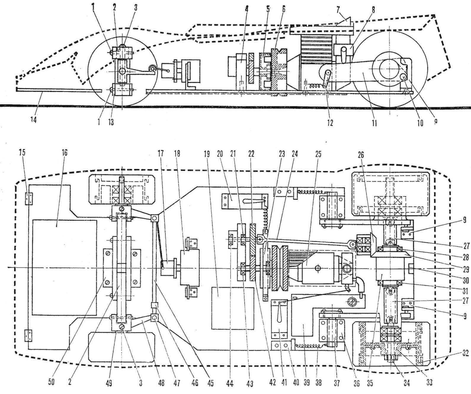
Fig. 2. Layout scheme of high-speed radio-controlled models Petrov:
1 — horizontal pins, 2,13 — wishbone front suspension, 3 — pin (Ø 4 mm), 4. — front bearings; 5 — drum clutch and brake, 6 — flywheel, 7 — inlet, 8 — carb, 9 — limit switches-lever, 10 — pin, 11 — swinging arm rear suspension, 12 lever — spring isolator, 14 — frame, 15 — loop body mounting, 16 — canister with batteries, 17 — mechanism of protection impact load, 18 — servo turning the front wheels, 19 — receiver with a decoder, 20 — servo brake drive, 21, 28, 31, 43, 44 — the bearings 22, 42 — led (Ø 39 mm) and host (Ø 25 mm) gear, 23 — band brake, 24 — cardan (Ø 5 mm), 25 — engine (dotted line shows the dimensions of the radiator), 26, 29 — master and slave gear, a 27 — side universal joints, 30 — lock mounting body 32, the disc wheel, 33 — split cone, 34 — axle shaft, 35 — differential, 36 — front of lever, 37 — axis (Ø 6 mm) 38 — spring (Ø 8 mm, 10 turns, wire Ø 1.5 mm EIA), 39 fuel tank, 40 — area of attachment of the spring 41, the servo drive gas engine, 45 — rod of a steering trapeze (Ø 4 mm), 46 — nut adjustment front toe, 47 — ball joint 48, the lever 49 swinging axle, 50 — strut front mount.
After selecting a prototype, and detailed acquaintance with him to begin tracing the models in natural size.
The most simple method is the increase of drawing points with the applied mesh. After drawing the model, you need to make at least one copy, Then take the drawing and it begin pre-configuration (Fig. 2). In case, if you already have the equipment and the engine, which can be expanded and rearranged according to the drawing, the task becomes much easier. If not, you need to make layouts of all nodes (to glue the matchboxes) in full size. The engine can take anyone as their sizes differ slightly. By the way, if you have no engine working volume of 3.5 cm3, you should not spend time looking for one, headroom of any good engine 2.5 cm3 is more than enough to achieve excellent results.
THE DEVICE PROTECT THE SERVO FROM SHOCK LOADS
We already talked about the fact that the motion model on uneven track or when hitting an obstacle the front wheels are experiencing heavy loads. If a rotating arm is connected to the servo control wheels hard thrust, all the bumps are transmitted to the relatively fragile in most plastic parts. Consequently, the node of the servo-mechanism with a rotary lever wheel should be provided with a buffer device
The site must meet the following requirements:
1) at negative loads on the servo, not to exceed the allowable, it is rigidly without play connected with a rotary lever and transfers the force to the wheels of the model; 2) when you return the servo to neutral position the wheels are also retained in the neutral position regardless of the direction of reciprocal movement; 3) when exceeding the permissible loads unblocking rods without a significant increase in the forces acting on the servomechanism. The swivel arms (with the wheels) are rejected until the limiters (stops) in the chassis; 4) after the termination of the excessive load, thrust, and therefore the wheels of the model automatically, without operator intervention, return to normal operating position and fixed in it with a certain force. Need to mention that all these requirements are satisfied only node, as shown in figure 1D, and with some approximation node 1G.
Consider the advantages and disadvantages of possible structures. Figure 1A shows the pull wire OVS is the double loop in the middle. Due to the elastic properties of loops such pull well prevents the servo, but it does not fixes the position of the wheels, and, as a consequence, the model spontaneously picks on track — manage is very difficult.
In figure 1B, the connection damper type without locking rods. The disadvantages are the same as in the previous example. However, due to the simplicity of the design is a compound often used in the first sea trials of the chassis. The competition is almost never used.
Figure 1C shows another device of the damping type, but with a locking neutral position by using a steel ball, which is included in the recess in the tie bar front suspension. With a sharp increase in the load, the ball goes out of gear, bushing stays in place, and a transverse rod, compressing the spring, moves with coke. The disadvantage of this device is the inability (due to lack of the elastic force of the spring) and its return to normal position quickly, the Operator throws the handle of the transmitter to full deflection in the same direction where he turned the wheel upon impact. Then, if, for example, the wheels turned to the right, cross the pull shifts to the left (relative to bushing) and remains in this position. Enough to turn the handle of the transmitter to the right — sleeve shift to the left (wheels and pull it does not move), the ball will engage with the transverse rod. But as often I can not see where he turned the wheel (and no time to think — the model is moving), it is necessary to manipulate both sides. The whole construction is reliable and is used often.
Most of the foreign athletes today prefer to scheme, shown in figure 1G. During normal operation, the leading arm with your finger leads to a spring of the appropriate form, and that drags the clutch lever. If you exceed the load, the levers are disconnected by unwinding the spring. The only drawback is the occurrence of the torque transmitted by the spring. In the normal position, without load, it is the smallest and increases with the unlocking levers. If you ignore this, then the mechanism is almost fully meets all the requirements.
The mechanism shown in figure 1D, was first used on the model E. Petrova, and now many modelers have appreciated its benefits. Through the use of two rods to the servo-mechanism type “Varioprop” and convert the reciprocating motion of the Cams of the machine in the rotation — a leading wedge (see Fig. 1D) is achieved by reducing the friction and distortions of the moving toothed slats in the servo-mechanism and thereby increases the transmitted torque. Especially it should be taken into account when using the servomechanisms of the type “Novapro”. Wingman (straight) the wedge engages with the leading and restrained by springs, the compression force of which is regulated by a screw. Lead wedge made of duralumin, driven — steel, and his sharp edges are rounded so that the contact surface of the wedges was the greatest. From the angle at the vertex of a wedge (usually about 90°) depends on the maximum transmitted torque. When removing the wedges torque practically does not change and remains less than the maximum.
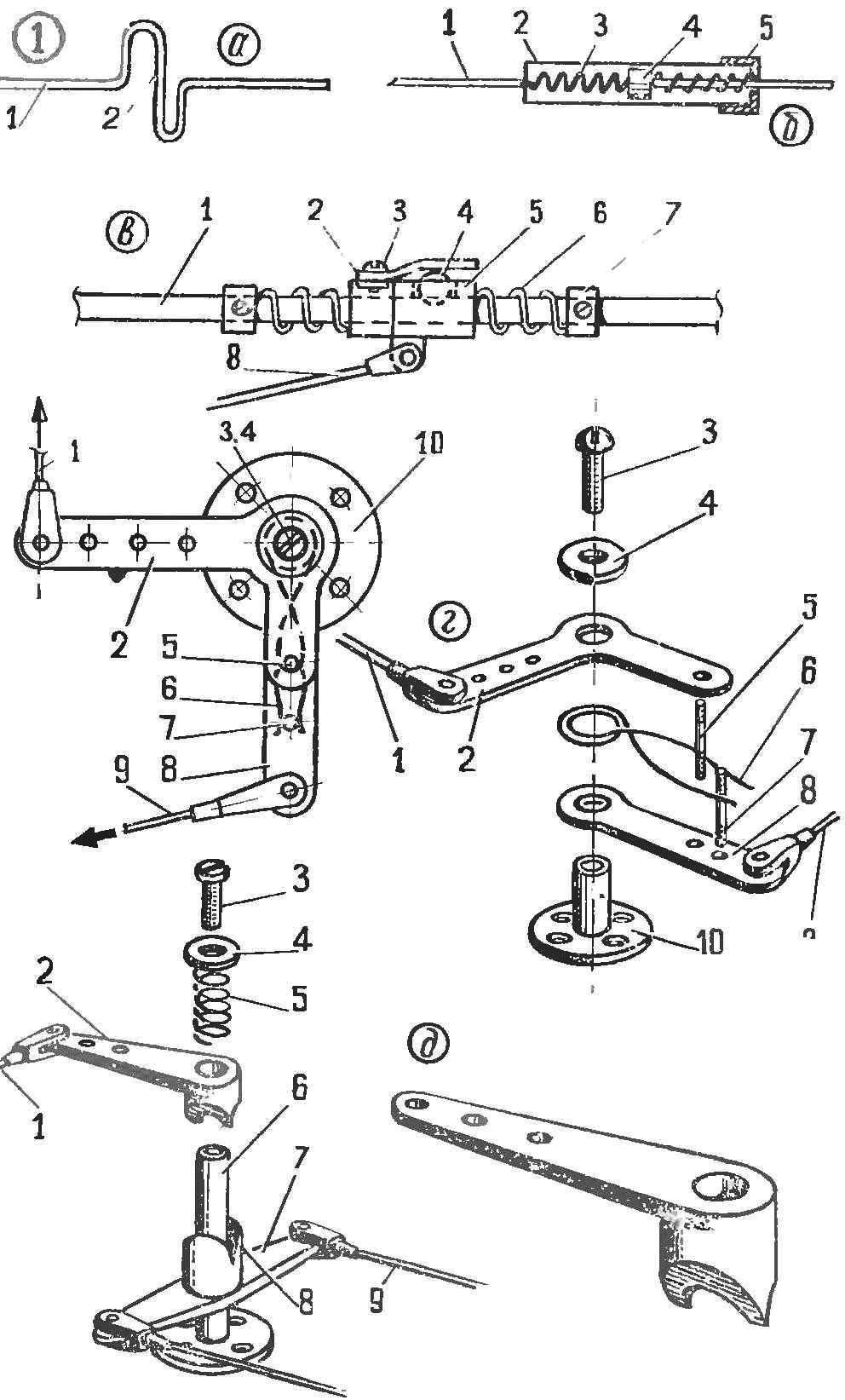
Fig. 1. Safety devices:
A — the simplest pull: 1 — wire OVS Ø 1 mm, 2 — loop; B — pull damper: 1 — wire OVS Ø 1 — 2 mm, 2 — metal glass, 3 — spring 4 — piston 5 — bottom of the glass with a hole (soldering to the glass); To fuse with fixation of neutral: 1 — lateral pull front suspension, 2 — flat-spring 3 — screw 4 — bulb steel, 5 — Bush with hole for bulb, 6 — spring, 7 — restrictive sleeve, 8 — thirst for power; G — fuse type “Variofan”: 1 — pull to the servo-mechanism, 2 — lead lever, 3 screws, 4 — puck, 5 — lead finger, 6 — spring, 7 — driven finger 8 — clutch lever 9 — thrust to the steering lever of a front suspension, 10 — axle mechanism with the disc attachment; D — fuse designs Petrov: 1 — pull to the steering arm of the front suspension, 2 — clutch lever with wedge 3 — screw 4 — washer 5 — spring, 6 — axis mechanism 7 is the leading lever back clip, 8 — reverse wedge, 9 — pull to the servo.
To set the mechanism at work is necessary, turning (carefully) lever the clutch and preloading the spring holding the wedges in a connected position, as long as the transmitted force starts to move the servo mechanism is de-energized. The more rapid rotation of the lever should be the unlock mechanism. Practice has shown that this is the easiest and most accurate method of selection efforts, but it requires extreme caution. This system returns very quickly to the wheels of the model in the position corresponding to the handle position of the transmitter, and the task of the operator — just follow the course and manage the model. To protect the joints of the wedges from the dirt, before the race abundantly to lubricate any grease lubrication, better yet close the cover (a rubber tube).
AUTOMATIC CLUTCH
The node of the mechanical clutch is an integral part of any car or model. After numerous experiments, almost all designers are offering automatic centrifugal clutch. It is relatively simple to manufacture, comprises few parts, is adjustable within wide limits, ‘reliable and durable, finally, allows to use a wide range of materials.
The principle of operation of the following mechanism. Pads clutch mounted on the flywheel of the engine and are held inoperative and at low speed springs. With increasing engine speed, the elastic force of the spring, which almost does not change, becomes less necessary: Fц.with. = mw2R, where m is the reduced mass of pads with springs, w — angular velocity, R is the radius of the turn. Diverge pads are pressed to the driven drum, rigidly connected through a gear system to the drive wheels of the model. If the brake on the model at this time is off, it begins to move. The use of such a clutch provides a soft connection and slippage of the pad during a sudden stop of the drive wheels, for example, during the attack on the barrier. It is important for the reduction of negative loads on the engine parts working in extreme conditions.
The clutch components are usually made of the following materials: flywheel — steel, brass, aluminum; grip pads — cast iron, brass, Ferodo, kaprolon, silicone, rubber; clutch drum — steel. Figures 2 and 3 show variants of structures of different clutches. The automatic clutch shown in figure 3, compares favorably with pre-existing fact that it is going to the motor shaft and is secured with one nut. This allows you to adjust its work on the stand and model to put in finished form. For the first time this kind of traction we have in the country used 10. Black and Petrov on the model class f-I “Lotus-79”.
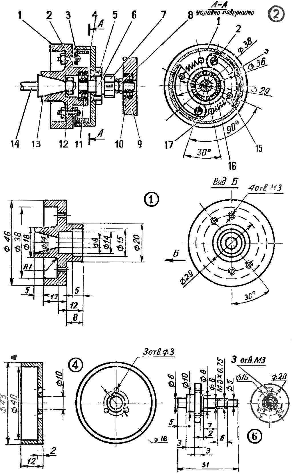
Fig. 2. Device for automatic coupling of the traditional type (for engines of 2.5—3.5 cm3):
1 — handwheel, 2 — screws mounting pad, 3 — pad clutch-4 — clutch drum-clutch, 5 — screw, 6 — axis led, 7 — gear, 8 — nut, 9 — front (mounted separately to the body), 10 — bearing 5X13, 11 — 6X16 bearing, 12 — a nut of fastening of a flywheel, the 13 cone washer, 14 — axis motor 15, 17 — M3 screws, 16 for tensioning the spring.
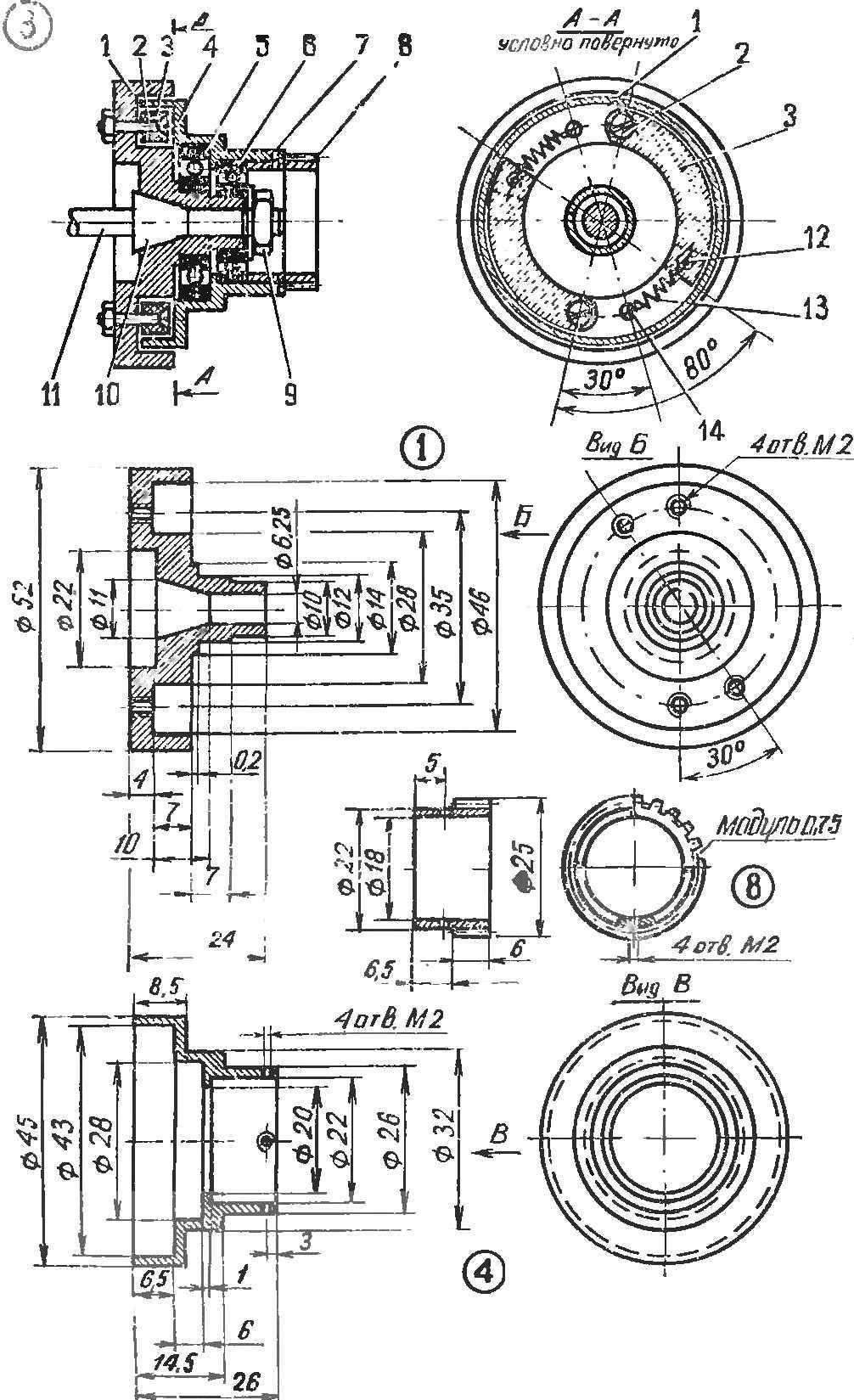
Fig. 3. Automatic clutch construction Petrov (on the engine type “N”):
1 — flywheel 2 — bolt mounting pad, 3 — pad clutch-4 — clutch drum, 5 — bearing 12X28, 6 — bearing 10X22, 7 — stud fastening drive sprocket, 8 — gear, 9 — fixing nut, 10 — cone washer, 11 — motor, 12 — the screw of fastening of the spring to the block, 13 — spring, 14 — bolt the springs to the flywheel.
Briefly about the design. The driving gear is taken larger diameters (Ø 25 mm) to reduce lateral pressure on the motor shaft. If it is welded to the drum over the bearing (which can take a smaller outside diameter), overall length of mechanism is reduced by more than 10 mm, and this will positively affect engine operation. Connections (traction) differential better to do it through gear, with cardan transmission. However, in the previous embodiment (Fig. 3) mechanism has proven itself in work. As shown, the clutch must transmit a force when the engine is not less than 0.5—0.75 maximum rpm, since motor torque will be optimal. The model accelerates with maximum acceleration, and while throwing the gas engine will be faster to disconnect from the drive wheels and allow the machine to go, for example, on the turns coasting. When braking, if the engine is not disconnected, it may stall.
DIFFERENTIAL
The advantages of using differential PA models internal combustion engines is obvious. You can make the drive axle for the models without differential, but the dynamic qualities of the chassis, especially on the turns, will be much worse. You need to take into account such an external factor: all the tracks for models of class f-I and f-II have a significantly greater number of left turns than right, and consequently more wear out much right wheels. The result is the straight model no differential to be much to lose in a considerable speed the engine power will go to equalize the diameters of the left and right wheels will increase and the slip of the rear wheels. The differentials used gear of any type.
FUEL TANK
The tank shape and the place of its installation on the model play a significant role in maintaining stable engine operation. You want to ensure proper fuel delivery in all modes: the sharp acceleration and braking, rotate the model, rollover, etc. have Very well proved design, shown in figure 4.
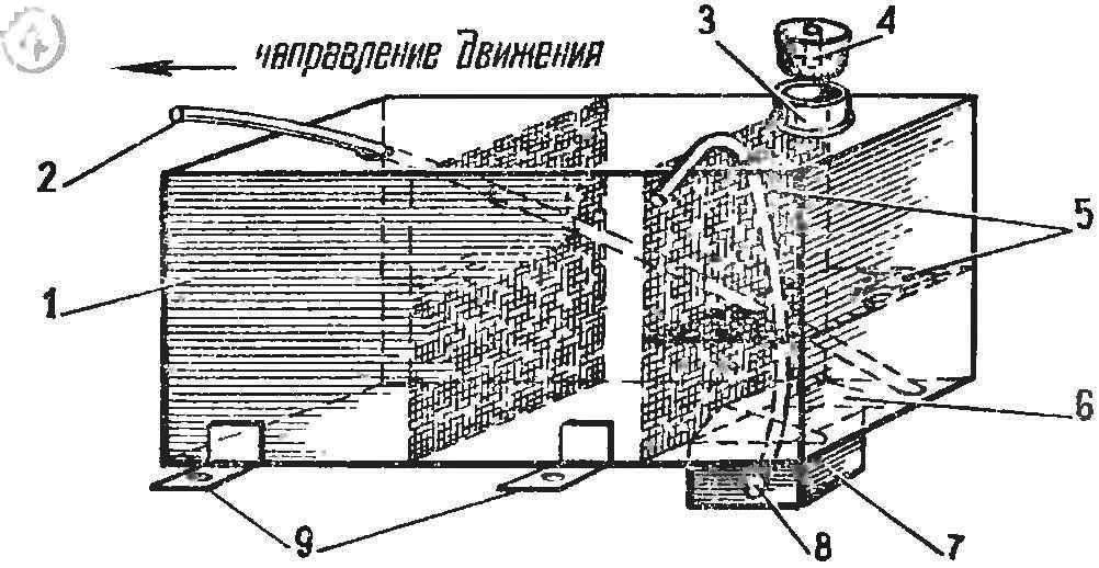
Fig. 4. Fuel tank:
1 — housing tank, 2 — drain pipe, 3 — neck tank, 4 — tube, 5 — copper mesh, 6 — roll feeder, 7 — feeder, 8 — feed tube, 9 — foot attachment.
The tank is soldered from thin steel (0.1 mm), has the form of a rectangular parallelepiped. It soldered a very thin copper mesh (two vertical layers and one horizontal), similar to that put model aircraft on the carburetor of the engine as the air filter. Neck tank is wide (Ø12 — 14 mm) is needed for a quick fill of fuel. She closed with a rubber stopper with holes for drainage. The tube is pressed tightly to the tank body model. The tank is soldered into the drain pipe, the upper end of which is filled with tin, and the drilled hole Ø0,1 mm.
At the top of the tank for brazing is planted “feeder” sides of the fuel supply tube enters the engine. As shown, the tank of this design, if it is filled at least halfway, delivers fuel with 10-15 even upside down. In the normal position model it in all modes works flawlessly. Due to the large area grid well clean the fuel from impurities for a long time.
THE FIRST WORKOUT
During the first training sessions should be guided by the following rules. Again and again to check up reliability of fastening of all the major sites, and detailed, the oil in the bearings and friction components and remove the excess grease. The batteries power the transmitter and on-Board equipment will recharge and check the battery capacity. Don’t forget just before the workout to test the operation of instruments without running the engine as close to the transmitter, and the distance of the highest removal. This should be done together.
For training it is advisable to choose a smooth paved area is relatively large and, importantly, without fences (particularly sidewalks) and away from power lines and powerful electrical devices such as transformer substations, etc.
At the first runs, moving at low and medium speeds (15-25 km/h), check and adjust the operation of the carburetor, brakes, set with a trimmer front wheels so that no operator intervention model was moving in a straight line at least 30-40 m at any speed. Turns first perform slower. The pre-training is performed only on the marked track. Same race in a circle practically do not give the necessary skills.
For marking trails it is best to apply the “impact-safe” baby nylon toy — skittles dice: they are less spoil the model with arrivals. Gradually increase speed to maximum. Modern races are held at average velocities of 25-30 km/h, and abroad is even higher — up to 45-50 km/h. This requires not only immediate response operator (it is necessary to take into account that you are driving and the team you submitted, delayed equipment ka 0.2 s), but also testing automaticity in the selection of solutions to supply commands to the model. Remember that any inaccuracy in the flow of the team, especially associated with stop, is equivalent to the loss of a quarter or the crap half the distance of the track.
After training, take the time to wash the model with gasoline, ether, lubricating all parts and especially the bearings, to carry out minor repairs or to replace individual parts.
TABLE COMPARATIVE CHARACTERISTICS OF THE PARAMETERS OF THE FRONT AXLE
TECHNICAL CHARACTERISTICS OF THE MODEL FORMULA F-II
Overall dimensions, mm:
length — 486,3
width of greatest — 232
height — 140
base — 298,4
Wing, mm:
length — 222
width 69.9 per
Track, mm:
front — 181,5
rear — 168,7
Tyre size, mm:
front — width 34,5 Ø 78,5
rear width 50, Ø 85,5
Dry weight, kg — 4,5
Weight distribution, % — 45/55
Engine performance:
power, kW/l/s — 0,45/0,6
the number of revolutions in min — 16 000
purge — cross
volume capacity, cm3 and 3.22
piston stroke, mm — 16
diameter of cylinder, mm — 16
Differential 6 cylindrical gears
Driveline — 3
Gear ratio — 4:1
The volume of tank, cm3 — 123,5
Clutch — automatic
Brake — band
Wheel drive — rear
E. PETROV
Recommend to read
 HOW TO REPAIR AIR CONDITIONER?
Mobile air conditioning RS-09 warm air was purchased in mid 2009 the Company Air Sonic has set the official warranty period for its products to 12 months, subject to the rules of... “BUSTILAT” DO
Glue "Bustilat" — a great helper in the household: they can bond a variety of materials. Another advantage is the simplicity of the composition, and therefore, the ability to cook it...
