
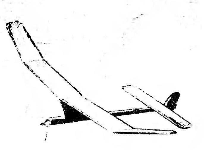
Classic simplicity of design, ease of construction and high technology are the advantages of the proposed timemay Svobodnaya model with an engine cylinder capacity of 1.5 cm3. To build this you can even in a poorly equipped aircraft modeling circles. Along with these advantages, the model has the more important differences, is invaluable in terms of exploitation of its athletes students. Reliability behavior timemay take-off phase, regardless of the weather conditions, consistently flawless transition from take-off to planning, but also the immutability of total flight time. The last factor is so important that is completely worth the somewhat archaic view of the model due to the high pylon, a legacy of the airfoil and unusual for a modern model of a combination of values of elongation, squares his shoulders and bearing surfaces. However, not afraid to repeat: the high stability of the results of this flight Tierney puts it in the real conditions of competition almost head and shoulders above the more modern technology in the subclass expense of building a traditional school. All the above fully applies to the option Microdrive MK-17 “Junior”, modified in accordance with earlier publications in the “Modeller-designer”, and with the upgraded MDS in 1.5.
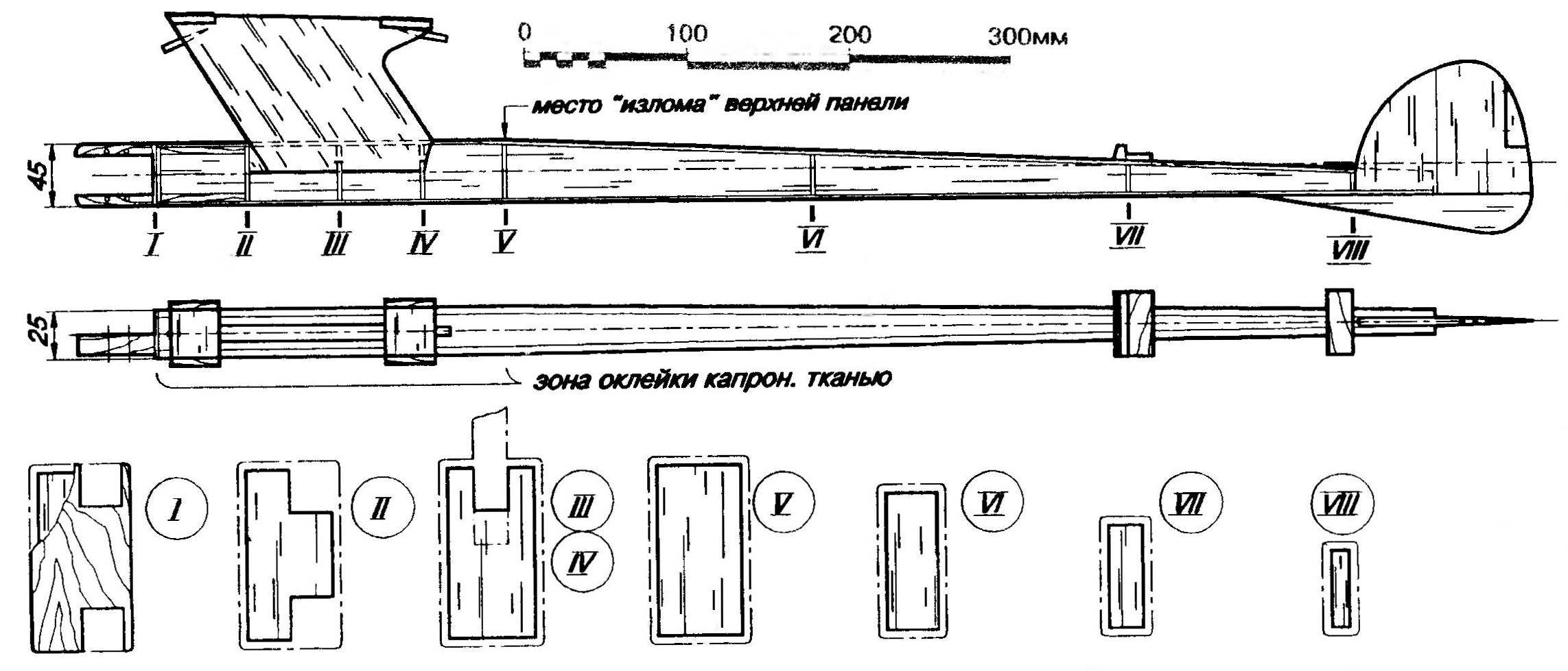
Tierney the fuselage is assembled from four plates balsa 3 mm balsa frames and of two beech boards motor section 9,5×12 mm. Front power frames duplicated: item balsa glued a plate made of plywood with a thickness of 1.5 mm, uniting the bars of the motor with the power side and closing the front ends of the latter.
The fuselage is going on the simplest slipway-Board. First glued the right and left side panels with all the frames and engine mount – note: forming the lower contour of the fuselage straight, which simplifies Assembly. The installation angle of the stabilizer is specified by the slant of the upper generatrix, and the engine is mounted without Vicosa.
The next step is to insert the keel plate of balsa wood with a thickness of 3 mm and workpiece pylon of solid balsa wood with a thickness of 7 mm. All loaded nodes spilled epoxy. After curing, the parts, if necessary, stripped and in its place stick the upper and lower sheathing panels. This operation is also carried out on the slipway, eliminating the possibility of twisting the entire fuselage. Then widened Logement platform of the pylon balsa plates with a thickness of 7 mm from the edge of the plates of 1-mm plywood, necessary to fix the angle of the “V” of the center section of the wing. Mounted the cradle of a stabilizer, cut from plywood in the thickness 1,5…2 mm and expanded ahead of the hard rail of lime; put the lower part of the keel.
The pylon are glued bamboo pins with a diameter of 3 mm under the rubber band wing mounting, after which the model is carefully ground and the fuselage glued long-grain paper for quality amalite. Before cording paper preferably with the help of enamel-paste over the front part of the fuselage thin nylon cloth. This will help him to become simply “indestructible” regardless of the accuracy of operation. After finishing cut from the keel, the rudder (shown in the figures) and is hung on two strips of soft aluminum with a thickness of 1 mm, and the exposed ends of the wood are varnished.
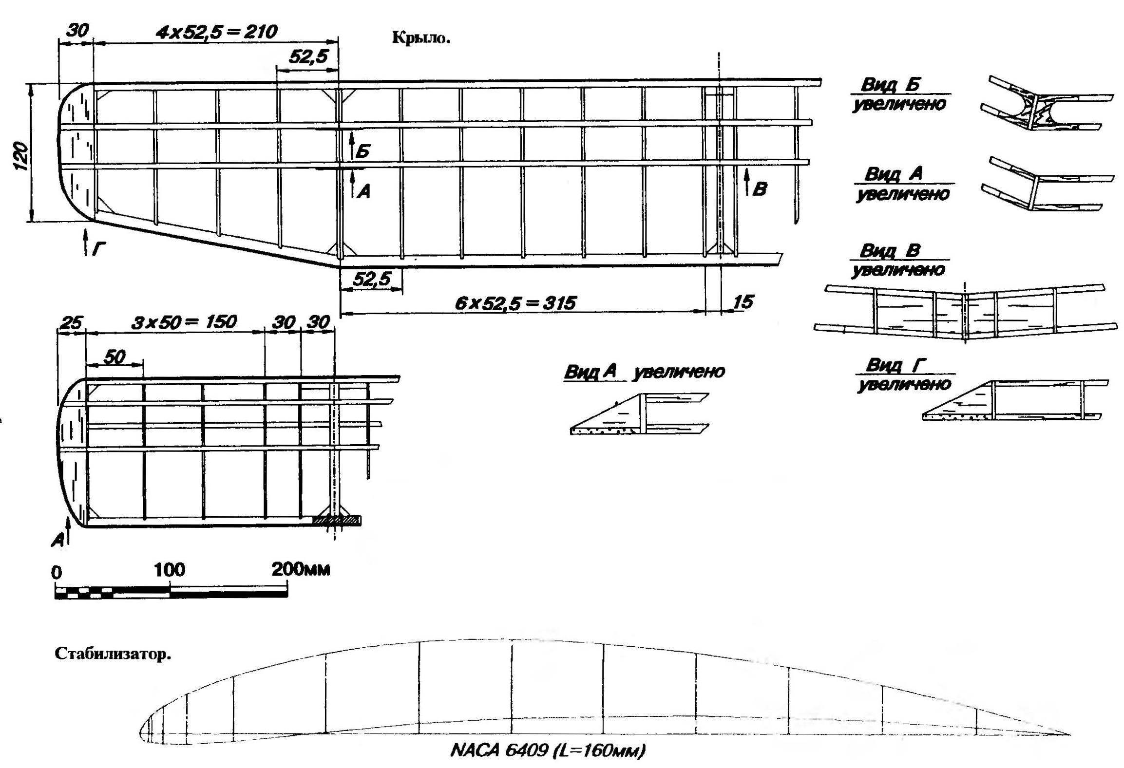
The wing is made in classical power scheme. All ribs are cut from brushed lime plates with a thickness of about 1.5 mm (butt rib in the center and the junction of the center section in the “ears” are duplicated). Shelf front longitudinal — pine or spruce slats cross-section 3×3 mm (such a small cross-section valid in connection with the great thickness of the airfoil), and the back of thick balsa the same section. The trailing edge is balsa, section 3×14 mm, front
hewed out a similar, but more dense material. If desired, the front edge of pine, slightly reducing the cross section. Both halves of the center section and “ears” collected separately on flat stocks. On the last set ending balsa plates with a thickness of 3 mm and the end of the insertion member. Then, using plywood overlays all elements of the wing together. In the joints of the edge are enhanced fake scarves. The final Assembly it is important to carefully check that the corners of the “V” of the individual elements corresponds exactly to the General form of the model.
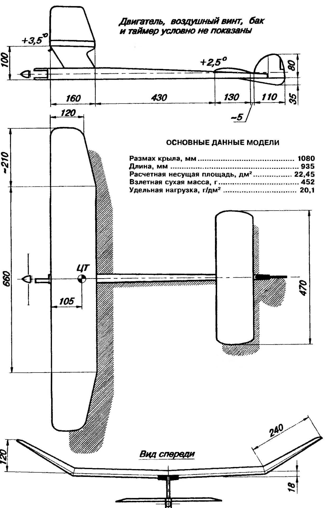
Basic geometrical parameters Svobodnaya Tierney model aircraft with internal combustion engine working volume of 1.5 cm
Fuselage.
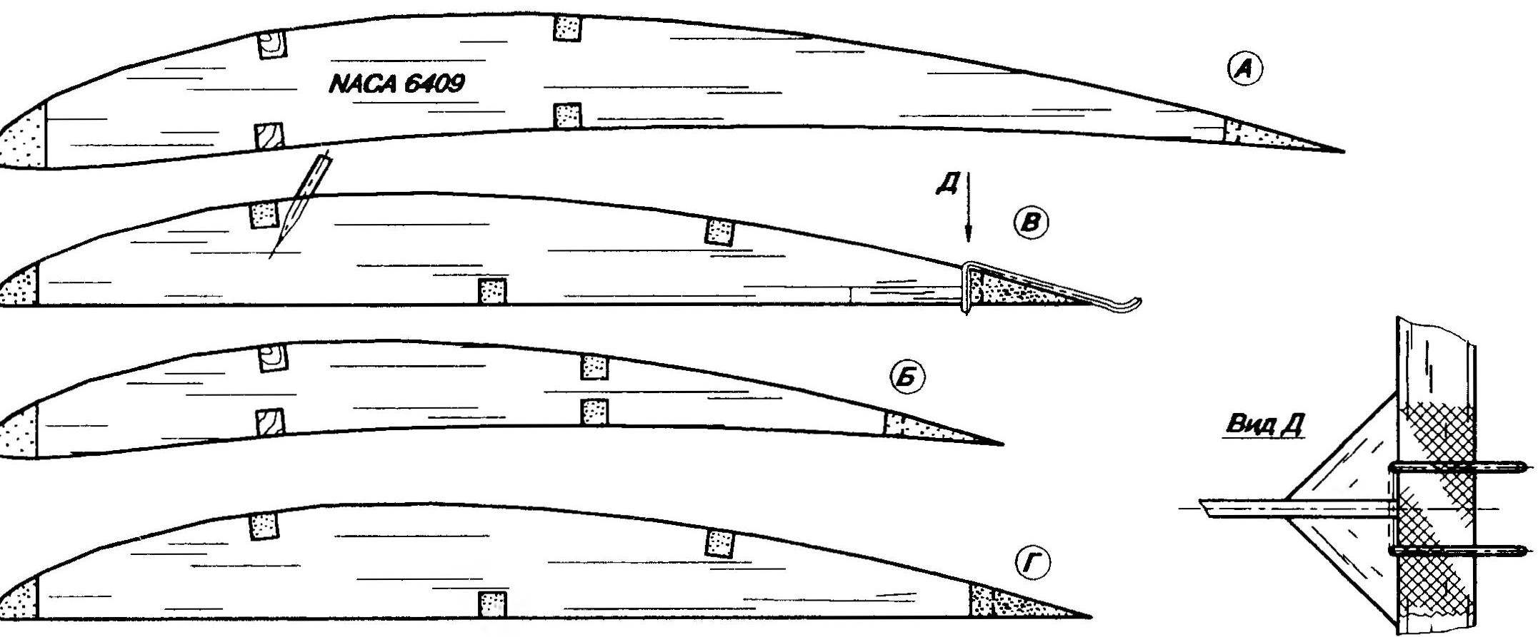
profile Templates:
— typical cross-section of the wing center section B— end section of the rib “eye” wing In the Central section of the stabilizer. G — typical cross-section of the stabilizer.
Important stage — cording wing long-fibre paper on Amalia. The quality of the execution of this operation will depend on all the flight characteristics Tierney. Before starting skinny, frame sanded and the joints of the edges in the ground “fractures” paste over
strips of nylon fabric shirinoi of about 20 mm. Then wrap the surface double-coated with a nitrocellulose lacquer with intermediate drying and grinding. Macalintal paper glued with liquid Amalita, applying it on the outer side and Primera the seam with your fingers. After thorough drying, the covering is varnished. Note that price-tropinova sections of the wing should be completely flat, and the ears have end ribs of the same negative twist equal to 7 mm. Intermediate drying varnish and a final two-week exposure of the wing is held in its zanemarivanja in a makeshift slipway. If conditions allow, it is better to keep the model in the fixture, removing it only during transportation and flight.
The design of The stabilizer similar to the design of the wing. The only difference — all items are only from balsa. Rib — 2 mm thick, the stringers — a cross section of 3×3 mm and edge — SX and 10 mm. 5×6 Technology sheathing paper is also not different from those already described for the wing. Duplicated in the Central rib of the stabilizer is glued in a bamboo pin for the rubber loop, and at the rear edge of the nylon ribbon is fixed notched double hook wick restrictor flight time, call the professionals “decimalization Goldberg”.
Before the flyby, the model is carefully checked for the absence of ad hoc twists, clarifies the position of the center of gravity and mounting angles of the wing and stabilizer. The fuel tank is on the starboard side of the fuselage just behind the engine, and a timer limits the time of his work — on the left. After this is determined by the mass of the model: “polutorametrovy” engine it should be not less than 450 g. the Ballast weight cuts and is glued into the fuselage bottom, and centering under the stabilizer. It is from pieces of lead.
Debug test flights take place early on in the planning mode, in calm windless weather. When trajectory planning and flight models will be consistently satisfactory, move on to tests in the engine mode. With the engine set to 75% power, and a timer, put on 5 seconds, vigorously throw the model into the air at an angle of 80° to the horizon. Don’t forget: the rudder after debugging planning should be denied the right to 3 mm at the trailing edge!
Timer needs to climb almost vertically, rotating to the right along the axis of the fuselage. If the takeoff will be straight or with rotation left, adjust the position (the deviation) of the rudder. Spins again, bringing the power of movement
the gates to the maximum at the same time (5 s) operation. The perfect delivery model with pre-installed 10 with a timer makes a vertical takeoff, making 2.5 turns to the right, and after turning off the motor on a smooth upward trajectory comes to the planning of wind.
Established planning mode — smooth right turn, with a diameter of about 25 m. If the curve will be more energetic on the left ends, podstawy-libatomic loementech plates bonded lining thickness up to 0.8 mm. the position of the rudder in any case do not change. The deflection (as well as the axis of the engine) within a small range is used exclusively to adjust motor take-off. The final fine-tuning of the planning mode and hovering is due to a small displacement of the center of gravity. The Weights are securely glued into the fuselage.
Highly recommended for everyone, even a short run to put into action wick system determinatio. There were times when even in a quiet serene day time we went into “thermals” and landed only 4 hours, 25 km from the start. In any case, it is helpful to provide the model of your “business card” with a phone or address where you can return the model.
V. PTITSYN, head of the society
Recommend to read
 SINCE THE BUBBLE IS UNDER THE LINE
I think that many readers are not only sawing and plowing, but also relax with a fishing rod. When winding leads (loop the loop) on motoviltse on the line stay sharp bends. I propose to... WANTED TO FLY AND FLIES!
Hard to believe that everything is created by one person. Besides, not a graduate, but a simple fan design. As for the design and manufacture of completely heterogeneous machines...
