 Shortly after the end of the great Patriotic war in the Soviet Union began to receive numerous captured documents and samples of military equipment. Among them, in a single instance did the twin-engine multi-purpose aircraft Do 235А-1. The Bureau of new technology in TSAGI it has thoroughly studied and built technical details, which is the basis of this publication.
The main features of the machine was a tricycle landing gear support and the location of the engines in the fuselage. Front engine rotated in the pulling propeller and the second motor, mounted behind the cockpit (closer to the center of gravity), – a pusher propeller through an elongated shaft.
The Creator of the Do 335 Claudius Dornier has expressed interest in this arrangement, in 1919, using a tandem pulling and pushing propellers on the plane Gs 1. After 18 years, the Dornier took out a patent on the layout of the aircraft like the Do 335. The idea of an elongated shaft was first implemented on the experimental aircraft Go 9 with an 80-horsepower engine.
Creating a plane for such a scheme, we should not forget about the difficulties not only of an elongated shaft, but its take-off because it should eliminate contact of the propeller with the ground. For this it is necessary either to lengthen the main landing gear or the wing to make a turning. In any case, the drag reduction is consistently will not only improve speed characteristics, but heavier aircraft.
Still, the possibility of a substantial increase in flight speed won. In 1942 Dornier won the competition to create a light bomber “project 231”, capable of speeds up to 800 km/h with a 500-kg bomb load. After receiving the order, Dornier proceeded to a detailed design of the multipurpose aircraft of the Dornier Do 335. There were questions of creation on its basis of high-altitude reconnaissance, heavy “hunter” and double all-weather interceptor.
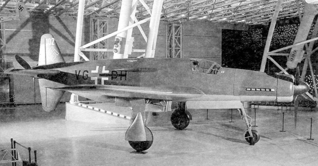
Do 335A-1 in the Museum of the Smithsonian institution (USA). Photos Of The Town Of Slutsk

General view of Do 335A-1
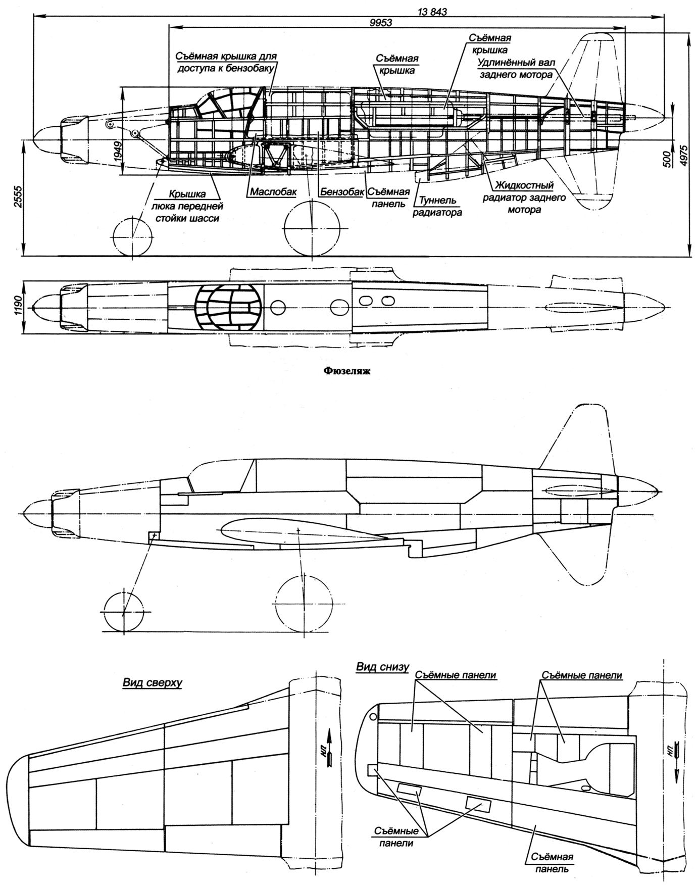
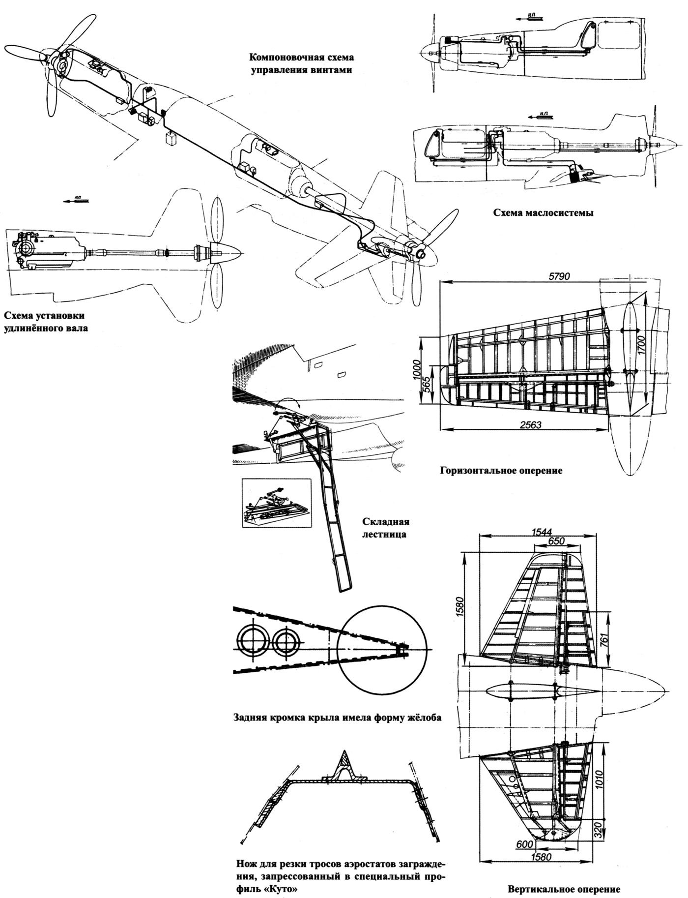
The pattern of the fuselage skin and wing
Development of the aircraft was completed in late 1942, the year and 26th of October next year it prototype under the designation Do 335V-1 with engines DB 603А-2 for the first time overcame the force of gravity.
Tests in General were successful. The aircraft with takeoff weight 10,000 kg could rise to a height of 10 km and fly at a distance up to 2000 km When it reached a speed of 750 km/h in flight with two working engines and 557 km/h – on one. This aircraft was named “Phil”, which translated from German means “Arrow”.
However, there was a lack of directional stability at high speed, but it was fixable.
It was planned to make 20 prototypes. To Do 335V-5 was mounted armament of one 30 mm cannon MK 103 and two MG 151 20 mm caliber ammunition for 70 and 200 rounds per gun respectively. In the cargo hold was located up to 1,000 kg of bombs of various calibers. But the age of the Do 335V-5 was short, in one of the test flights the plane crashed.
On the V-6 and V-7 continued factory testing. V7 subsequently transferred to the company “Junkers” for ground tests of the engines liquid-cooled Jumo-213A and 21ЗЕ, and V8 – the company “Daimler-Benz” to install engines DB-603Е-1. With regard to V-9, he, fully equipped with weapons, has become the benchmark for the series and was sent to Rechlin for testing.
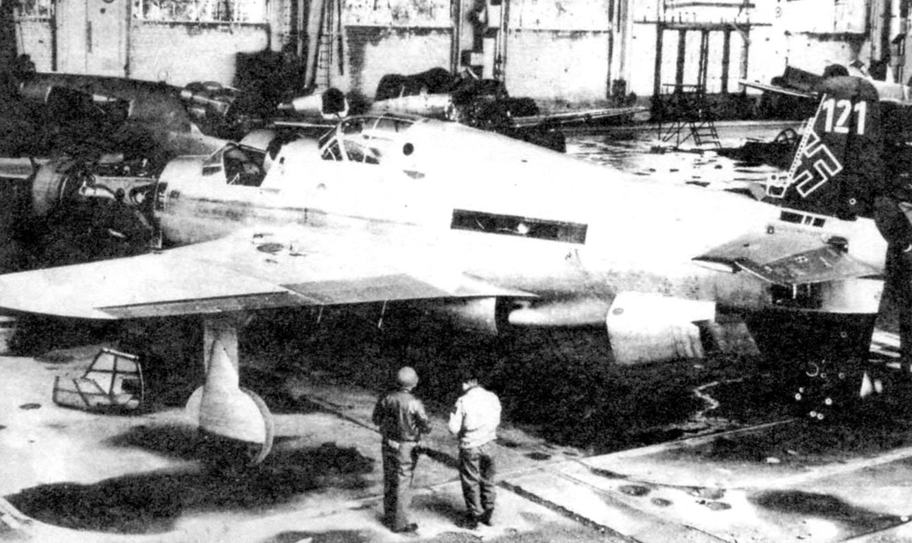
Assembling the double plane Do 335V-11
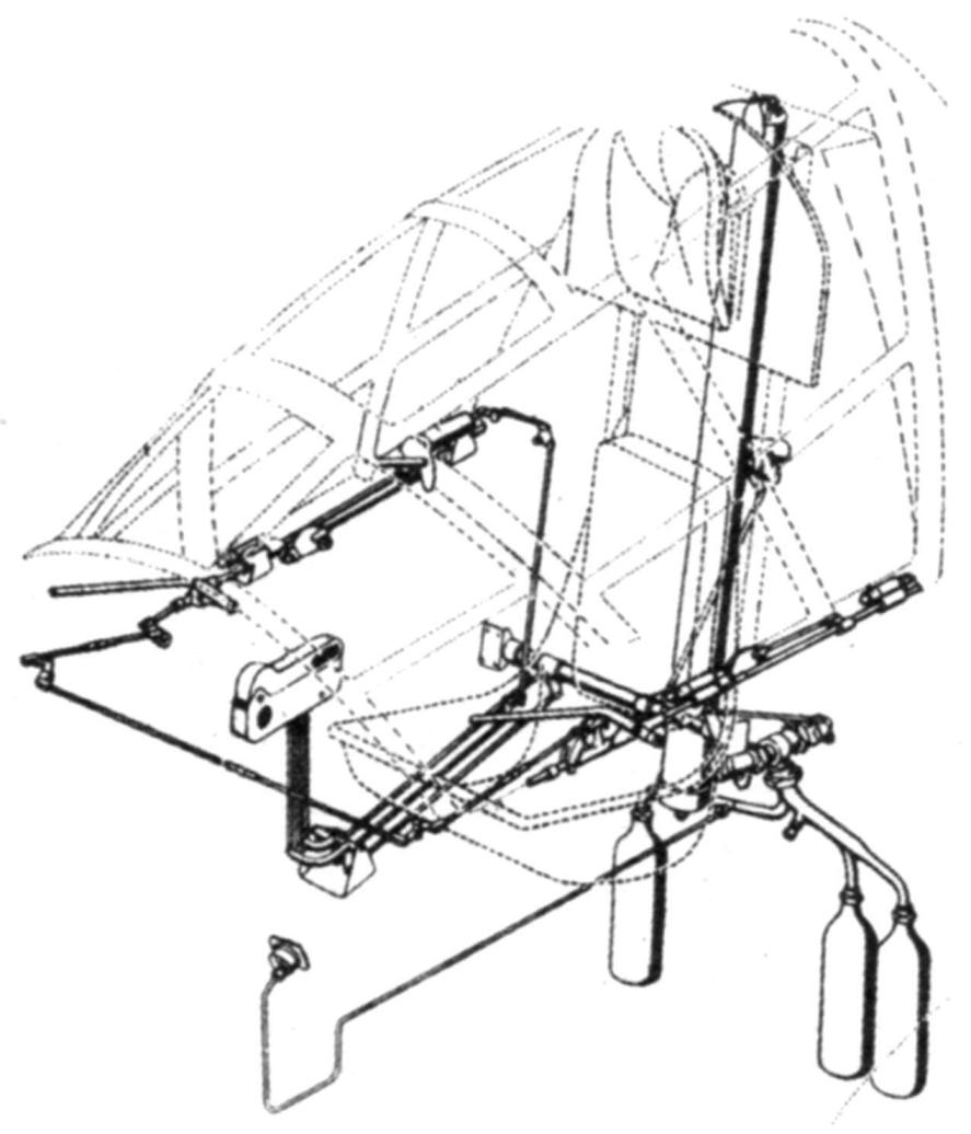
Scheme pneumatic emergency flushing of the lamp and the ejection seat
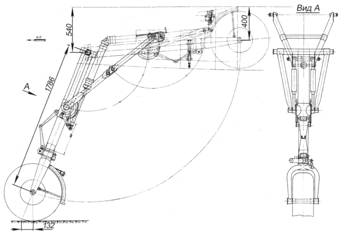
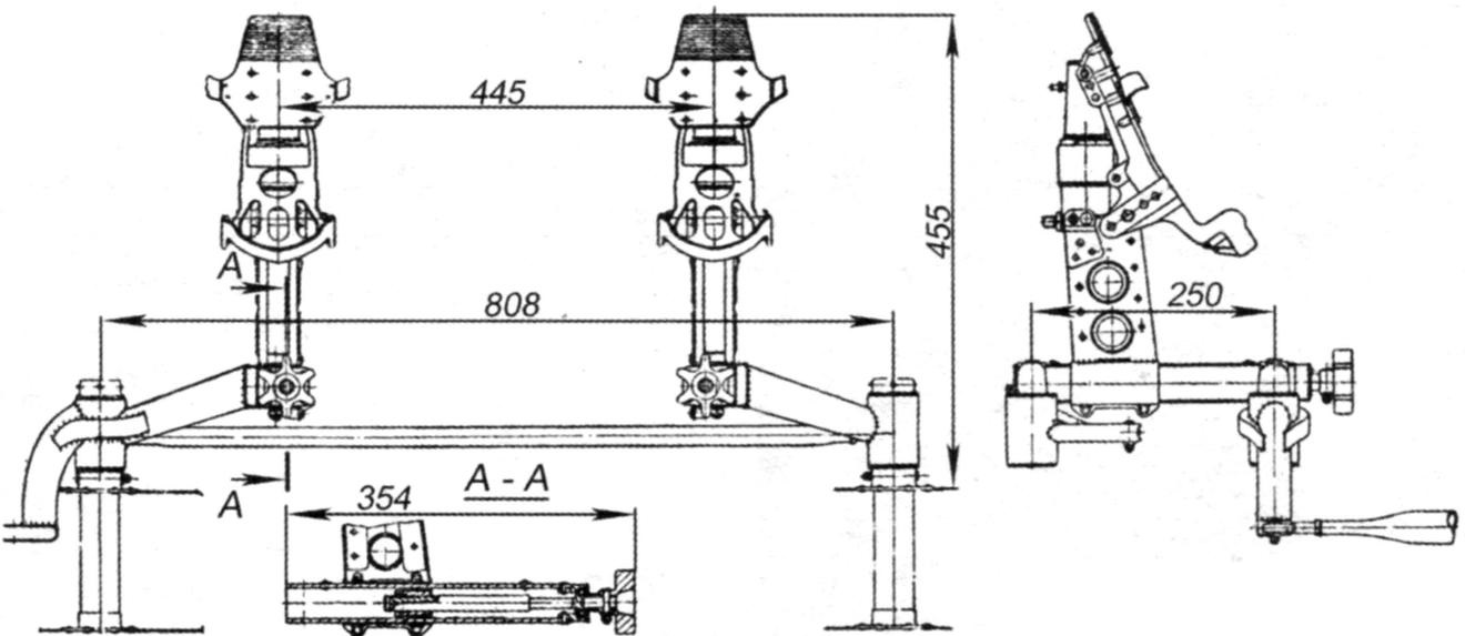
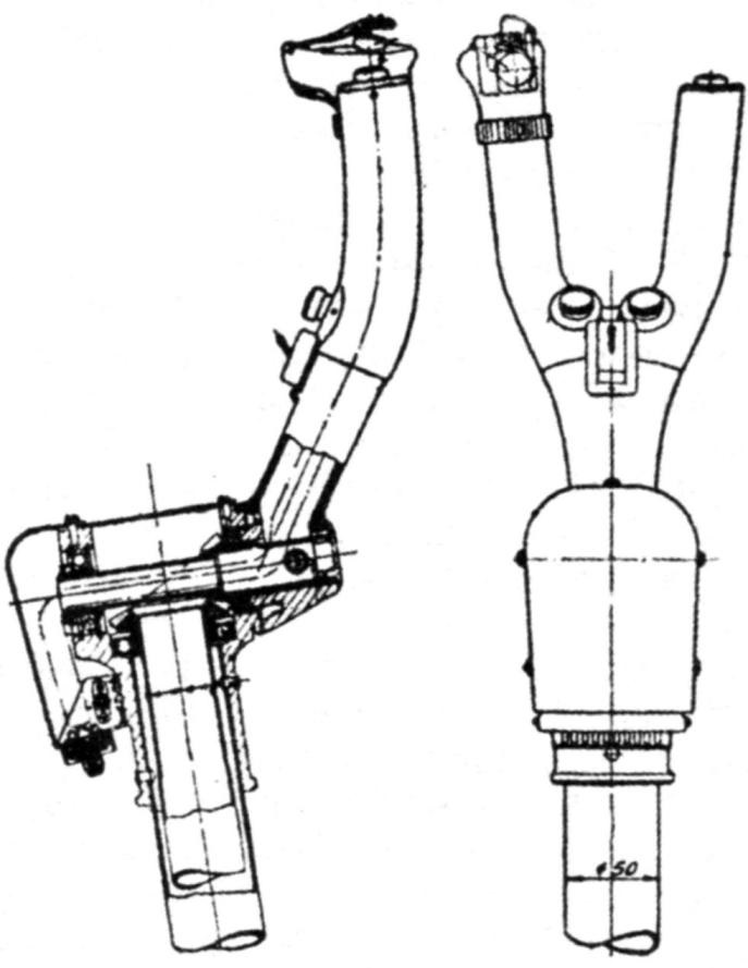
The front landing gear
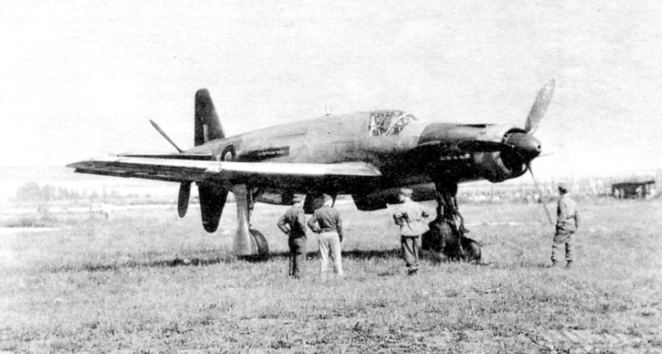
Do 335 with English identification marks
Do 335V-10 became the prototype all-weather double interceptor Do 335а-6 with engines DB-603А-2 radar and FuG-217J Neptun. To do this, had to redo the fuel tank and drop from the cargo compartment. The total amount of fuel amounted to 2300 L. Artillery armament remained unchanged. On engines supplied flame arrestors. As a result of the modifications the car is much heavier, and, as a consequence, worsened its performance.
Training cars with dual controls Do 335V-11 and V12 deprived of their weapons became the prototype serial A-10 with engines DB-603А-2 and A-12 with DB-603Е-1.
Do 335V13 received instead of a machine gun MG-151/15 in the front part of the fuselage cannon MG-151/20 cannon. The plane was supposed to become a prototype of serial Do 335В-1. The armament of the prototype Do 335В-2 (Do-335V-14) completed two 30-mm cannons MK-103 in the wing. These machines until the end of the war had to fly around. Six more prototypes were under construction, were never completed.
In the spring of 1944 German industry produced ten pre-production machines Do 335А-0, more than half of whom entered the military tests in the “335”.
Serial machines received the designation Do 335А. But production of the aircraft unfolded slowly. As can be seen from different sources, difficulties in mass production allowed until the end of war to hand over only 11 of the Luftwaffe (according to others, 13) Do 335А who did not manage to take part in the fighting. In addition, the project was still 15 cars.
Do 335А-1, was investigated in the BNT TSAGI, could be used as a fighter bomber.
The aircraft was a cantilever all-metal monoplane with low wing, cantilever tail surfaces and tricycle landing gear.
The fuselage – semi-monocoque, technology was divided into the front (to frame No. 12), medium (between the frames 12 and 19) and rear (to frame No. 25) part.
In the front between the frames # 1 and # 7 posted cockpit and under it is a niche cleaning the nose landing gear. Luke niches had two folds opened automatically, kinematically connected with the nose landing gear. For access to the cockpit from the left side of the fuselage puts the stairs. Some planes were equipped with folding ladder, retractable in samosogrevanie a manhole located in the wing.
Pedal foot control aircraft
The aircraft control stick
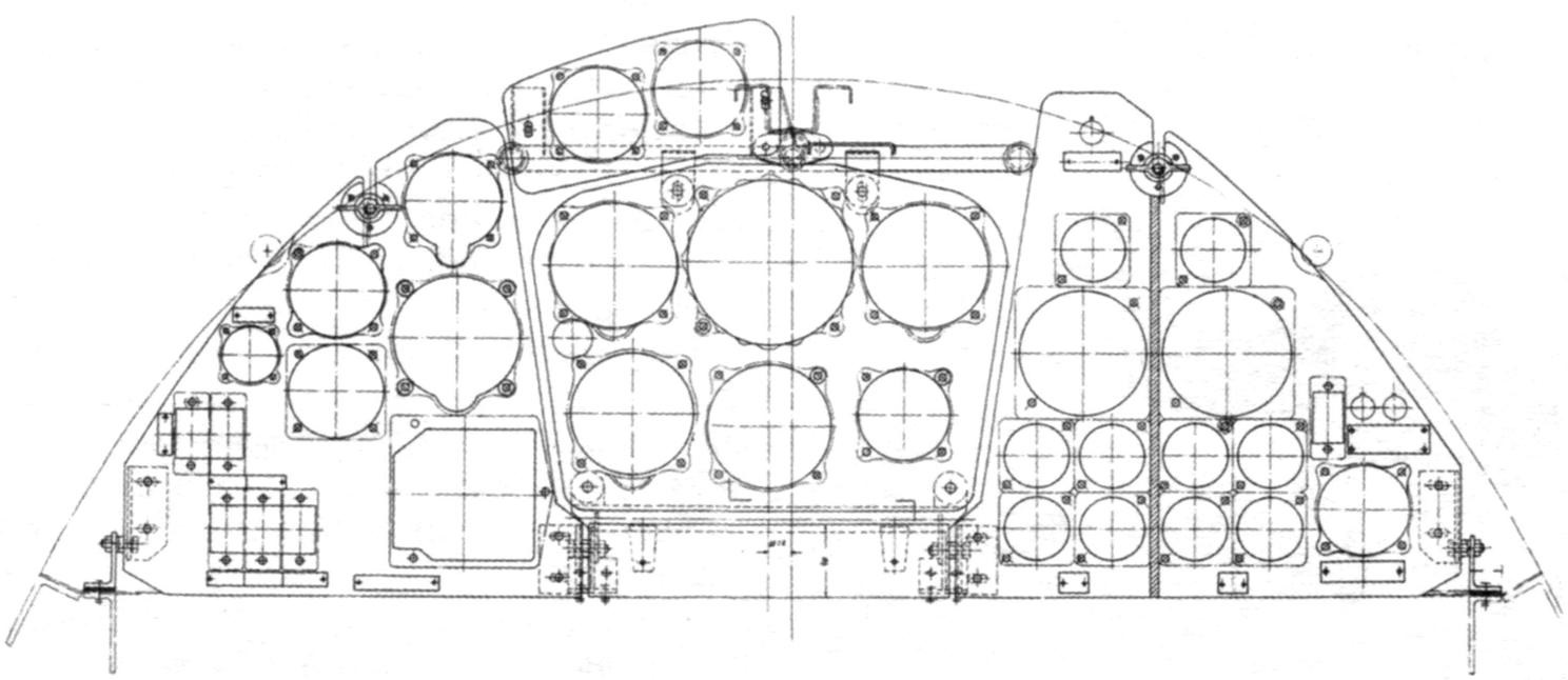
Dashboard pilot
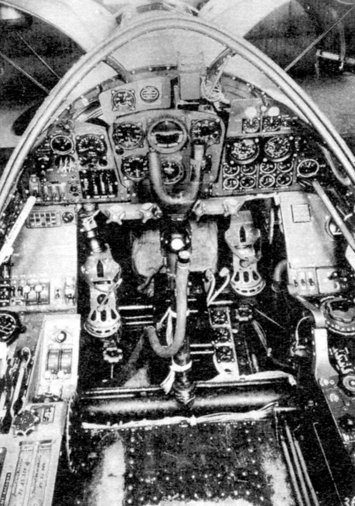
A fragment of the cockpit
Between the frames # 7 and # 12 are two oil and one gas tank, under which there was a cargo compartment with hardpoints bombs or extra fuel tank.
Between the frames 12 and 19 mounted rear engine, for which there were upper and two side hatch. In the rear fuselage are elongated motor shaft and cooler motor.
The lantern consists of a fixed shroud and a folding (right) part of the hinge attached on two pins to the fuselage. Provides the mechanism for emergency release of the lantern. In this case, the movable part of the lantern opened earlier. The cockpit glass cockpit is made of plexiglass with a thickness of 6-8 mm.
Ejection seat for pilot – metal. The catapult consists of a mechanism of ejection and two guides, made of aluminum alloy. Ejection is accomplished by compressed air fed from three cylinders at a pressure of 120 ATM. This allowed the pilot to leave the plane without ejection the top of the keel to a speed of 900 km/h.
The wing is single-spar, consists of two consoles that are attached to the fuselage with bolts type flange connection. Spar box-section caisson type, do not occur on airplanes of those years, worked well as bending and torsion.
The carrier surface was recruited from NACA profiles relative thickness at the root to 15% at the ends – 9%. Angle transverse V on the line socks -6° sweep on the leading edge from the axis of symmetry – 13°.
Placed on the wing, slotted flaps, hydraulic (hydraulic – electric) and drooping ailerons with trim tabs. On takeoff the flaps are deflected 30° and the landing at 50°. Under the leading edge of each console had knives pressed to a special profile “kuto”, cutting the ropes of the balloon barriers (section – I And L – L). The rope of the balloon, cut the leading edge of the wing with thickness of 0.5 – 0.75 mm, fell on a knife blade.
The trailing edge of the wing has the shape of a trench in accordance with the patent firm “Fieseler” from 1938 (the cross section W – W and U – U).
Between the ribs 14 and 16 to wear the left wing mounted landing light.
The tail Assembly was of cruciform shape, a cantilever with a symmetric profile.
Horizontal tail – trapezoidal shape in plan. The installation angle of the stabilizer is adjustable on the ground.
Vertical tail consists of upper and lower parts, which if necessary can be reset using explosive bolts. The upper part together with a pusher propeller is reset for 15 minutes before leaving the pilot of the aircraft without the use of catapults, and lower in the case of a landing with landing gear serves as a support for overturning aircraft at the tail.
The management plane is hard. The aircraft is equipped with mechanisms to change the gear ratios in the system control rudders and ailerons, which reduces the load on the arm and pedal at high speeds of flight.
The rudders and ailerons have the weight and aerodynamic balance. The upper rudder is pletner on the lower trimmer. Handlebar height two flatner and trimmer. The ailerons have trim-plenary. Management of all trimmers – hard from the steering mechanism located in the cab on the left control panel.
Control stick – steering type.
The power plant includes two 12-cylinder engine DB-603E liquid-cooled with separate cooling system. Launch engines ElectronicIndia starters of the company “Bosch”.
Propellers of the type VDM electric blades with a diameter of 3.5 m at the bow (pulling) and 3.3 m in the tail (pusher).
The total stock of petrol – 1980 years, including the supply tank with a volume of 1230 L. Two additional drop tank on 375 l were suspended on consoles of the wing. According to the TSAGI (NO. 351 BITS, 1947) additional tanks with a volume of 310 liters was located in the toe of the wing. The oil tank had a capacity of 95 liters

The main landing gear is equipped with oil-pneumatic shock absorbers and wheel sizes 1015×380 mm with double-sided drum brakes. Main landing wheels and landing gear retracted towards the fuselage into a recess, located between the 1st and 12th ribs.
The front support is provided with a damper shimmy and wheel sizes 685×250 mm and melanephelinites absorber.
The release and retraction – of the total hydraulic system.
The tail support rods pivotally mounted on the lower keel, and its oil-pneumatic shock absorber is enclosed in the fairing at the bottom of which is riveted a steel snake.
Although the aircraft is a Dornier do-235А-1, was investigated in TSAGI BIT, there was no weapons, it was found that it included the gun one MK-103 30 mm caliber ammunition 70 rounds, firing through the hub of the front propeller and two synchronized 20-mm gun MK-151 with ammunition 200 rounds, mounted in the front part of the fuselage over the engine.
Bomb load of the aircraft in the bomber variant was located in the fuselage cargo Bay under the wing in the following combinations: 8 bombs fire at 70 kg and two 250 kg and one 500 or one 1,000 kg In the cargo compartment suspension was allowed an extra fuel tank or reconnaissance photographic equipment.
According to foreign press, on the firing of guns and the bombing sight was intended for “Cry” 12.
The plane in addition to standard navigation and controlling of the devices had an electric autopilot firms “Patin”, gyro horizon electrical gyro, altimeter FUGN101 (up to 1500 m), two generator and the battery, connected VHF radio FUG16У (range of radio communication when flying in high altitude – up to 100 km and at an altitude of 300 m, 30 km), equipment blind landing FUGI25а with antenna in a wooden sock bottom of the keel, radiolucent. The defendant (“friend or foe”) FUG25a with starevol antenna under the right wing of the console was intended for recognition of ownership of the aircraft, ship based and ground-based radar.
The cockpit had a UV light. In addition, the aircraft was equipped with the air navigation (ANO) and two tail-lights at the top and bottom keels.
There was also an oxygen machine with four two-liter bottles and fire-fighting equipment.
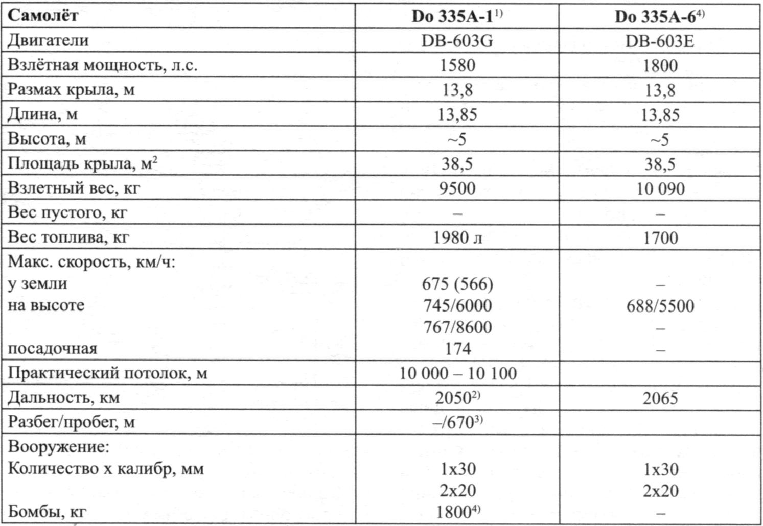
Engine data DB-603E

Basic data of the Do 335A-1
As follows from documentation of the company “Dornier”, single Do 235А-1 and A-3 was subsequently transformed into a double: Do 235А-5 and all-weather fighter-interceptor “A-6”, and the principal dimensions of the machine and its design has changed slightly.
On the basis of serial model “A-1” was planned to put the naked scout Do 335А-4 with two cameras (Rb-50/18) in cargo DB-and DB 603E-603LA respectively. Do335B-4 features a larger wing area and engines DB-603E. Two night-fighter version of Do 335B-6 with engines DB-603E had wings of various sizes, and high-altitude night fighters Do 335В-7 and b-8 were equipped motors DB-603LA.
On the basis of the Do 335 using the glider option V-4 was supposed to build double Do 435 interceptor with pressurized cockpit and a wooden outer wing panels larger scale. But this project remained on paper.
Combat use Do 335А was limited to only military test command “335”. Judging by the fact that in the domestic literature there is not even mention of the meetings with this plane, if any were, only on the Western front, controlled by the British and the Americans.
Nikolay YAKUBOVICH
Recommend to read
 Snow motorcycle
In “Modelist-Konstruktor” magazine No. 11’1991 I came across a description of motonarty — a tracked snowmobile built by the Matveychuk brothers from Zavodoukovsk, Tyumen Oblast, and named... RIGHT OR LEFT?
Turn indicator, which are explained in this article is intended for motorcycle "Java". The advantage of the self-made device before the industrial — low inertia: the scheme starts to...
