Readers of the magazine who became acquainted in issue No. 4’2006 with the tractor trailer by V. Kolyaskin were also interested in the mini-tractor itself by this amateur constructor. Today we publish a description of the manufacturing technology of this tractor and diagrams of its main units.
If you have a house in the country, and especially when you live there permanently, you can’t do without transport and tillage equipment. I had such equipment: I used a walk-behind tractor with cutters for soil cultivation, and a Zhiguli car with a trailer for cargo transportation.
But after my heart started acting up, I stopped getting behind the wheel of a car.
However, many household tasks were impossible to perform without a handy vehicle. That’s when the idea came to make a small tractor myself (buying a new one was beyond my means) and use it as a towing vehicle for a cargo car trailer. A chance encounter helped in this matter.
Once I came across a large bustling market and saw several mini-tractors nimbly darting between trading stalls and people, pulling carts behind them on trailers. One such machine stopped near me, and I didn’t miss the opportunity to ask the driver about it.
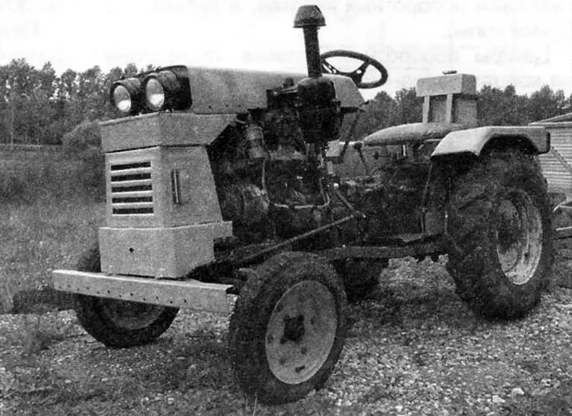
It turned out to be a “Sintai” mini-tractor of Chinese manufacture with a 2-cylinder 12-horsepower diesel engine and a rather unusual design: it had neither a frame (like other tractors or trucks) nor a load-bearing body (like passenger cars). The load-bearing elements were the power unit block and transmission housings (clutch, gearboxes, range selector). These elements were rigidly connected to each other with bolts, screws, or studs.
The driver also mentioned that they had the same broken mini-tractor in their hangar, which they first wanted to sell, but now use for spare parts, and showed me where it was stored. Some parts of the tractor were still preserved: front and rear axles, transmission units, body panels. But much, and most importantly the engine, unfortunately, was already gone.
After that, I spent several days thinking and assessing my capabilities for restoring the mini-tractor, then agreed on an acceptable price and purchased the remaining units and components.
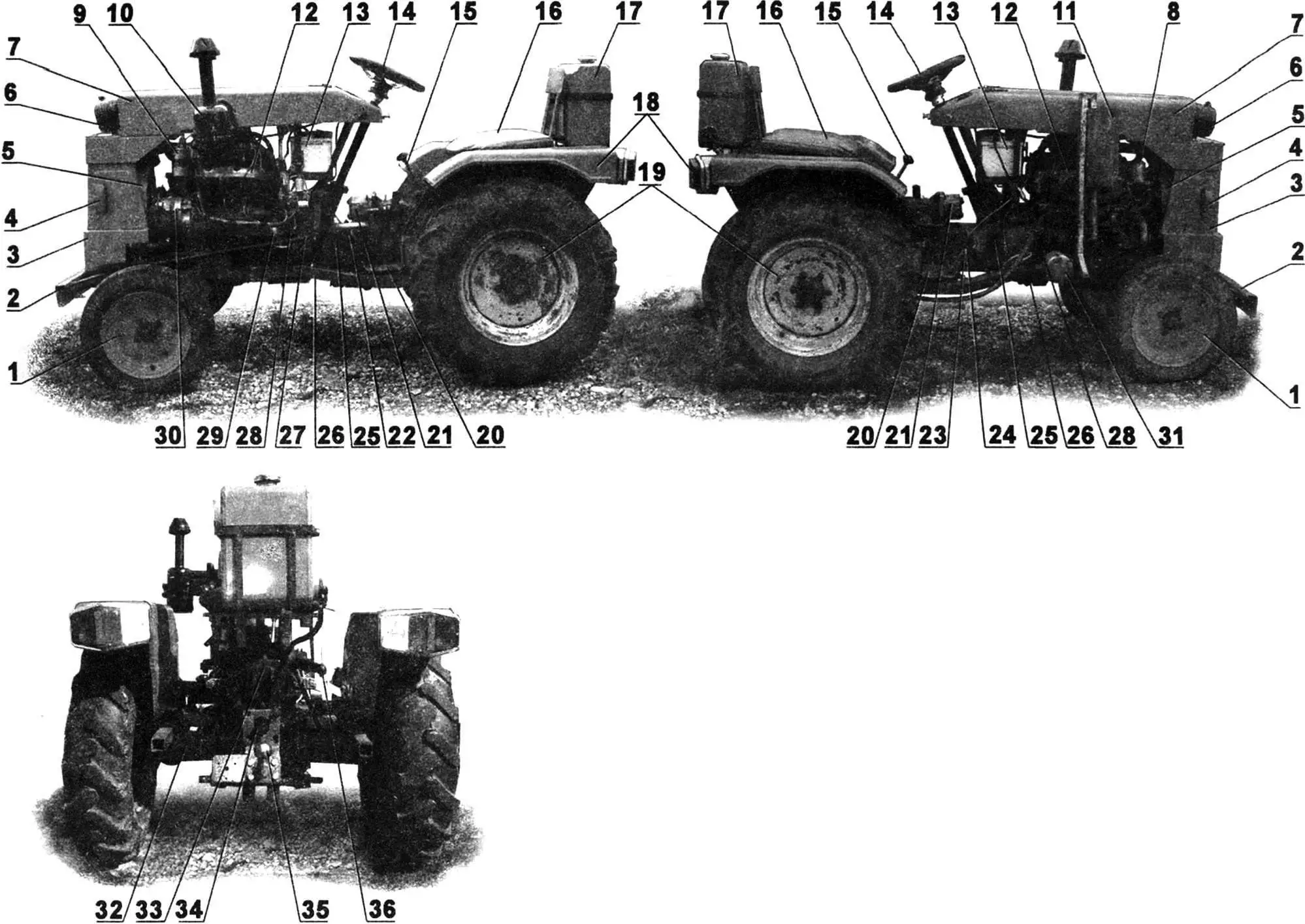
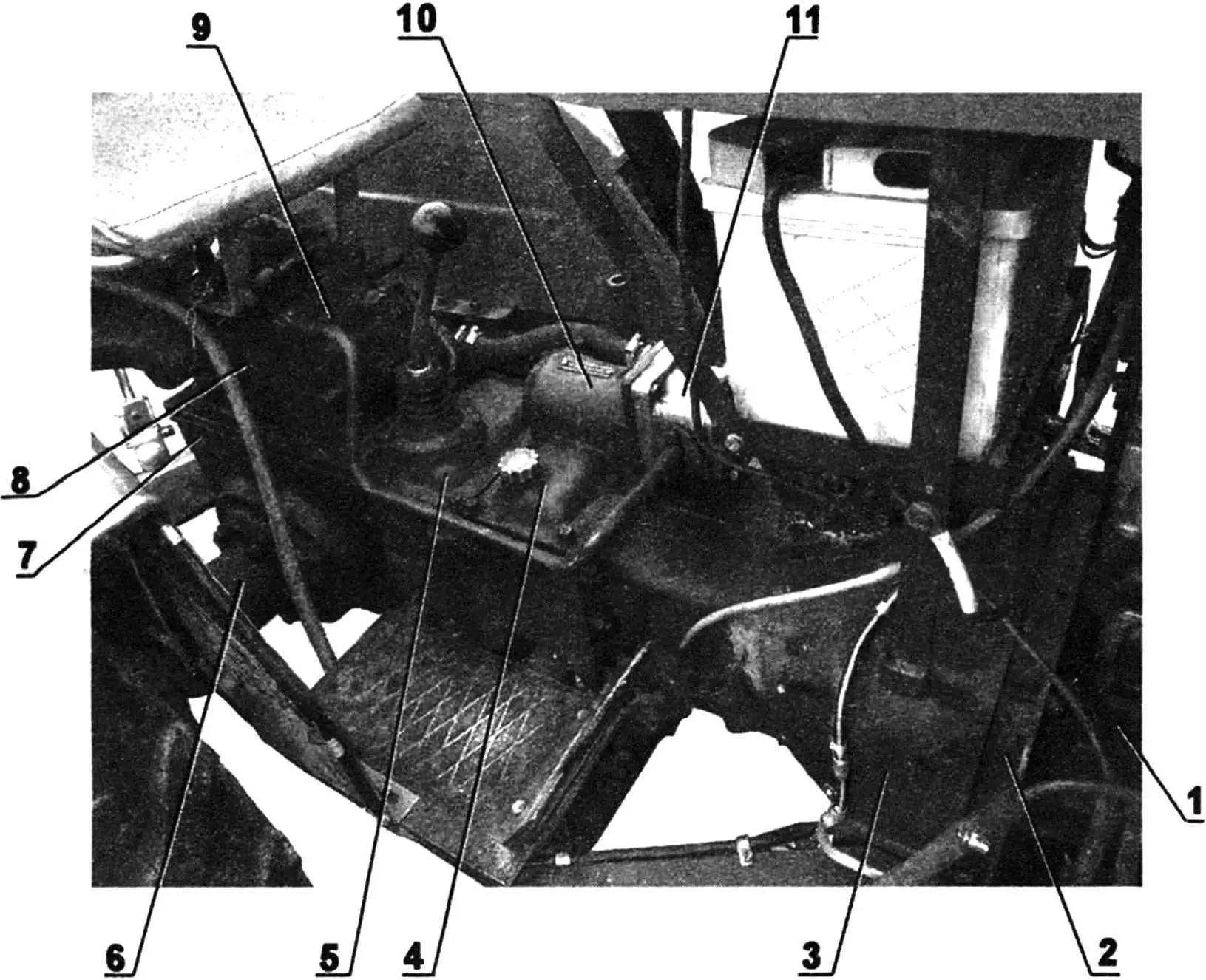
1 — front wheels; 2 — bumper (steel stamped channel 75x40x3); 3 — radiator grille; 4 — turn signals (from “Niva” car); 5 — fan (from foreign car); 6 — headlights (from agricultural machinery); 7 — hood; 8 — fine oil filter; 9 — high-voltage ignition coil (from “Moskvich-408” car); 10 — air filter; 11 — muffler (homemade); 12 — engine (from “Moskvich-412” car); 13 — battery (from passenger car); 14 — steering wheel (from passenger car); 15 — gear shift lever; 16 — seat (homemade); 17 — fuel tank; 18 — rear signal light blocks (from “Volga” GAZ-24 car); 19 — rear wheels (from “Belarus” tractor, front); 20 — foot platforms (steel corrugated sheet s3); 21 — oil pump; 22 — clutch pedal; 23 — brake pedal; 24 — throttle pedal; 25 — transmission units; 26 — frame (homemade); 27 — steering rod; 28 — fuel line (homemade); 29 — starter (from “Moskvich-408” car); 30 — generator (automotive); 31 — coarse oil filter; 32 — rear axle; 33 — hitch lever plunger pump; 34 — power take-off shaft; 35 — trailer hitch (homemade); 36 — hydraulic hitch lever (2 pcs.)
A friend gave me an engine from a “Moskvich-408” car with 50 hp. Its dimensions significantly exceeded those of the standard diesel, especially in length. Moreover, the Moskvich engine block was not designed to bear any load from the running gear. On the contrary, it itself needed additional support. Therefore, in addition to its reliable connection to the clutch housing, I had to think about making an additional load-bearing frame.
But I started restoring the mini-tractor not with the frame, but with the mentioned connection unit. The problem was that neither the dimensions, nor the number, nor the location of the mounting holes matched here. Amateur builders usually make a special adapter ring for this. In my case, the situation was further complicated by the fact that the engine had a cover with the starter drive gear (“Bendix”) significantly protruding toward the clutch. But after thinking and working, I solved this problem too: I made the adapter ring shaped (with a bypass for the “Bendix” cover), and in the clutch housing I made a cutout for the cover. I drilled the holes in the adapter’s mounting flange using a cardboard template, having marked on one side an impression from the cylinder block, and on the other — from the clutch housing.
But the troubles with the engine didn’t end there. It was necessary to somehow improve and make the cooling system more efficient. The standard system at low speeds simply could not ensure normal operation of the rather high-revving gasoline engine. Again, familiar amateur builders helped and supplied me with a compact dual-circuit radiator with a six-blade fan from some foreign car. During operation of the mini-tractor with this system, cooling problems never arose afterward.
I had to make the muffler for the engine myself — there simply was no standard one. Its design is extremely simple, but, as practice showed, quite effective: the exhaust turned out to be no louder than that of a passenger car. The muffler is elliptical, single-body, two-chamber, three-stage. The first stage of exhaust gas flow occurs when they exit through holes from the inner pipe of the intake pipe into the first chamber of the muffler. The second — when gases pass through the partition from one chamber to another. And the third — when gases enter the inner pipe of the exhaust pipe. At the same time, to prevent reverse flow of gases, I made the total area of holes in each subsequent stage slightly larger than in the previous one. The exhaust pipe is directed downward, as in passenger cars, and not upward, as is usually the case with tractors.
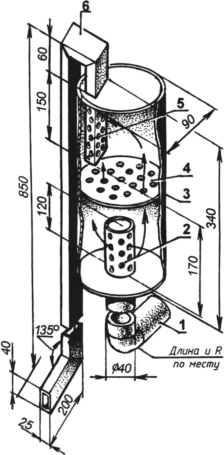
1 — intake pipe (pipe Ø40); 2 — inlet pipe (pipe Ø40); 3 — housing (steel sheet s2.5); 4 — partition (steel sheet s2.5); 5 — outlet pipe (pipe 40×25); 6 — exhaust pipe (pipe 40×25)
There was no standard generator on the engine, so I had to equip it with an old but still serviceable AC generator with a six-diode rectifier. I also bought a new battery for the electrical system.
I decided to keep the tractor air filter. It is, of course, large and requires maintenance, but it is very effective.
Now about the newly made frame. Although it is three-dimensional, it is quite simple. Its basis consists of two side members made from steel equal-leg angle No. 4 (40x40x4 mm). But the angles are joined lengthwise by the edges of their flanges and welded into a square tube.
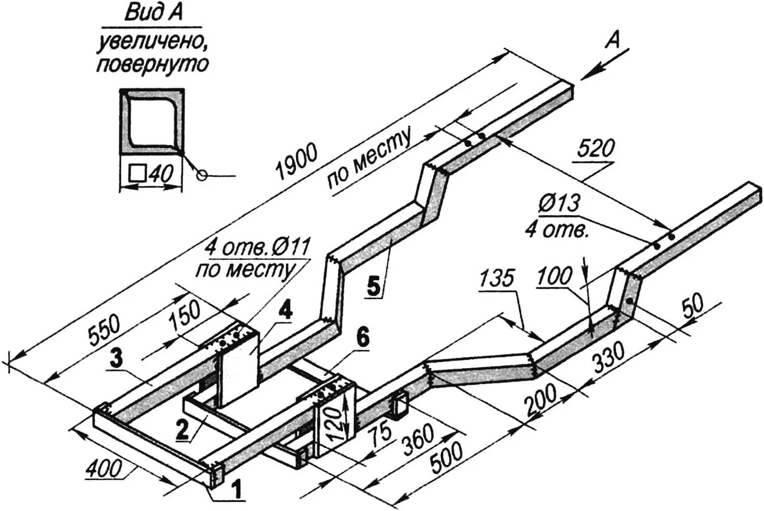
1 — console cross member (steel angle 50×50); 2 — side member cross member (steel angle 50×50); 3 — console (two angles 40×40, welded into square tube, 2 pcs.); 4 — post (steel sheet s5, 4 pcs.); 5 — side member (two angles 40×40, welded into square tube, 2 pcs.); 6 — engine cross member (steel sheet s5)
The side members are made composite, since along their length I had to both change the distance between them and raise the rear part above the front. The front part of the frame is narrower than the rear — to allow steering wheel turn. In addition, it is two-tier. This was necessitated by the need to fit the frame simultaneously to different units — the Moskvich engine and Chinese transmission components, as well as to the front axle beam suspension. The beam is suspended to the frame by means of a transition plate used from the same Chinese mini-tractor, but modified. Part of the plate was simply cut off as unnecessary, and new mounting holes were drilled in the lugs of the remaining part. To prevent the beam from wobbling on the central kingpin and hitting the frame, I attached thick rubber damping pads to the side members in these places.
The rear part of the frame is also three-dimensional, but here the side members are simply bent upward at a steep angle, then again directed in a horizontal plane. This bend was needed to connect and attach the frame to the rear axle beam from above — there were already M12 threaded holes there. With their help, here earlier (in the standard version) the fenders were attached to the beam through rather high spacer bushings. Now the place of the spacers is taken by the side member tubes and also pads made of hard rubber.
There are few transverse elements in the frame — two cross members and an engine cross member. They are all located in its front part. In the rear part, the connecting link of the frame is the rear axle beam. The bumper can also be considered part of the frame, but it is made as a separate element and attached to it with four M12 bolts. I made a new bumper — more massive and larger than the standard one, planning to mount a loader bucket on it in the future.
It should be noted that the holes in the frame for mounting units and components were drilled mainly in place, after careful alignment of their positions.
1 — engine; 2 — adapter with flywheel; 3 — clutch mechanism housing; 4 — auxiliary gearbox (range selector) housing; 5 — main gearbox housing with gear shift lever; 6 — right rear (drive) axle housing with half-shaft; 7 — final drive housing with differential and power take-off shaft; 8 — plunger pump with hitch lever lift; 9 — hydraulic distributor with lever; 10 — oil pump drive;
11 — oil pump
The rear axle is completely “Chinese”, but the wheels here had to be adapted from a “Belarus” tractor, although the tires on them are also standard.
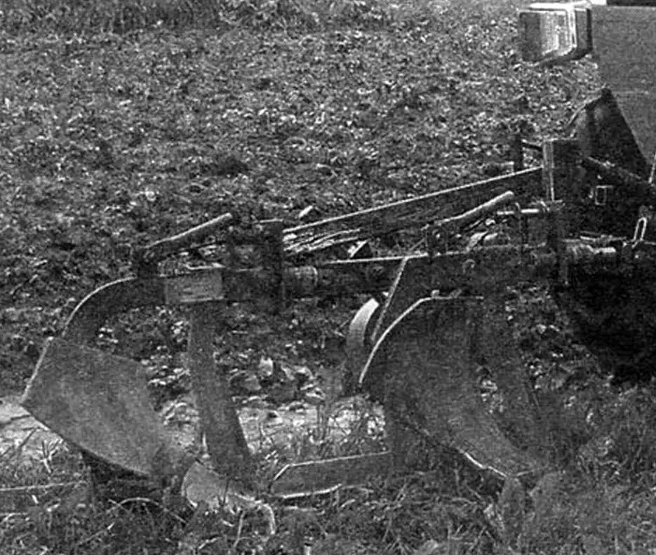
The hitch for connecting tillage implements together with a single-furrow plow was in the kit (or rather in the “incomplete kit”) with the mini-tractor. But since I installed a more powerful engine, to increase productivity during plowing I made another plowshare following the pattern and likeness of the first one and an additional unit for its attachment to the plow. And so that the machine wouldn’t slip due to lack of weight under such loads, I attached heavy cast iron discs to the wheels.
Since from the very beginning the mini-tractor was intended to be used as a towing vehicle for a cargo trailer from a passenger car, I made a ball trailer hitch for coupling with it. But in this unit, only the connection element is homemade, while the ball is of industrial manufacture. The trailer (it’s homemade) also has an industrially manufactured coupling device. Technical requirements prohibit the use of homemade products in devices of this type.
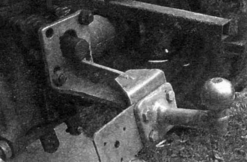
True, the hitch prevents free access to the power take-off shaft (PTO), but for now this mechanism remains unused and is covered with a plastic cap.
It should be noted that most controls: steering mechanism, brake system, clutch were in good order on the mini-tractor and I used them practically without modifications. Only due to the increased distance to the front axle I had to lengthen the longitudinal steering rod. It’s worth noting here that the tractor’s steering is quite simple and doesn’t have a steering linkage. The steering arms on the wheel spindles are connected to each other by a single transverse rod.
The hydraulic system was missing a pump and fine oil filter. These units fit without modification from domestic tractors. This fact indirectly confirmed the version heard at the market that the tractor was designed in our country.
There were no lighting signal devices in the purchased components, so they had to be purchased and installed anew. Front headlights — from agricultural machinery, turn signals — from a “Niva” car, rear signal light blocks — from a “Volga” GAZ-24.
V. KOLYASKIN
Recommend to read
 THE BMW GOES… THE ROOF!
Not so often we have to meet on city streets the car "coupe" or "convertible". However, at the dawn of its existence, almost all cars were just that — open, with soft rising tent. In the...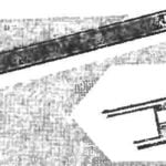 “DIMENSIONLESS” ROD
If in a ballpoint pen out of toothpaste, and long rods at hand was not, take the short splice and its extension from the part used stem, cut off from the writing site. To the working rod...
