 The space is calling the boys. Today almost every student dreams of becoming an astronaut as well as in the distant 30-ies of their peers dreamed of aviation. And like a decade ago, the guys are preparing for the upcoming tournaments. Learn in flying circles a theory to build complex models-copies “Union”, sport rockets, participate in competitions and contests. Only the all-Union competition “the Space” conducted by our magazine, gathers every year hundreds of young connoisseurs of space. The opening of this article a series of articles on rocket modeling, the editors hope that they will be an additional tool for club Directors and their participants.
Any flying model rocket has the following main parts: body, Stabilizers, parachuters system, guide rings, fairing and engine. Find out their purpose.
The housing serves to accommodate the engine and Parashurama system. Attached the stabilizers and guide rings. To give the model a good aerodynamic shape of the upper part of the body ends of the payload fairing. Stabilizers are necessary for the sustainability of the model in flight, and Parashurama system to slow free fall. With the help of guide rings model attached to the bar before takeoff. The motor generates the required thrust for flight.
THE CONSTRUCTION OF THE MODEL. The basic material for flying model rockets paper. The housing and the guide rings of paper glued together. Stabilizers are made from plywood or thin veneer. Paper parts are glued carpentry or casein glue and other nitrocream.
Manufacturer model starting with the case. The simplest model rockets it is cylindrical. The mandrel may be any round rod with a diameter more than 20 mm, since this size is the most common engine. It to be easily inserted, the diameter should be slightly larger.
Important geometric parameters of the shell model are: a diameter d and the elongation λ, i.e. the ratio of the length of the housing 1 to the diameter d (λ = l/d). The elongation of most model rockets is equal to 15-20. Therefore, it is possible to determine the size of the paper blanks to the housing. The width of the workpiece is calculated by the formula of the circumference L = πd. The result is multiplied by two (if the case of two layers) and add 10-15 mm to the allowance for the seam. If the mandrel 021 mm, the width of the workpiece will be about 145 mm.
You can easily do: to wrap twice around the mandrel thread or strip of paper, add 10-15 mm, and it becomes clear what should be the width of the workpiece housing. Keep in mind that the paper fibres must be positioned along the mandrel. In this case, the paper curls without kinks.
The length of the workpiece is calculated by the formula l = λ·d. Substituting known values, we obtain l = 20·21 = 420 mm. Wrap the blank around the mandrel once, the remaining part of the paper over the glue, let it dry a bit and wrap the second time. You get a paper tube that will be the case of the model. After drying, clean with fine emery cloth stitch and glue residue cover case nitrocream.
Now take an ordinary round pencil, wrap and glue it on the tube with a length of 50-60 mm in three or four layers. Letting it dry out, cut with a knife into rings with a width of 10-12 mm. They are the guide rings.
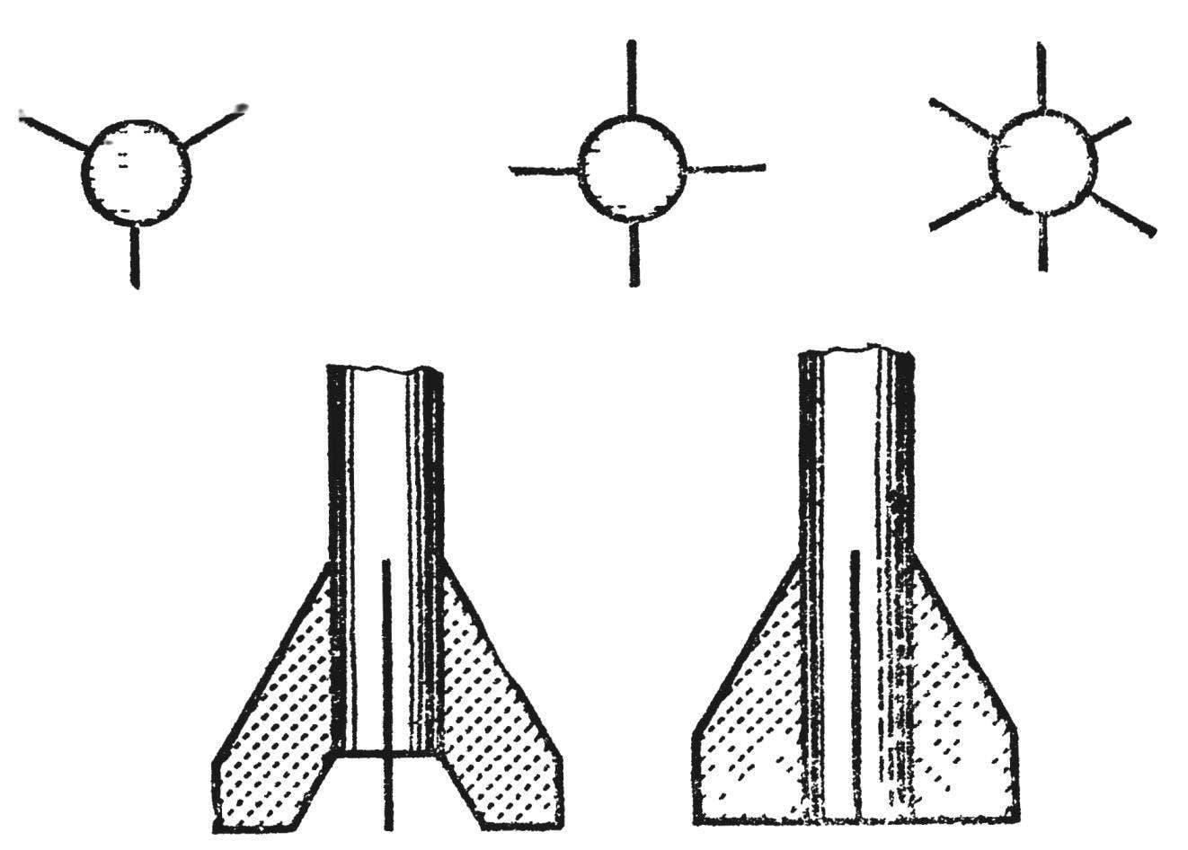
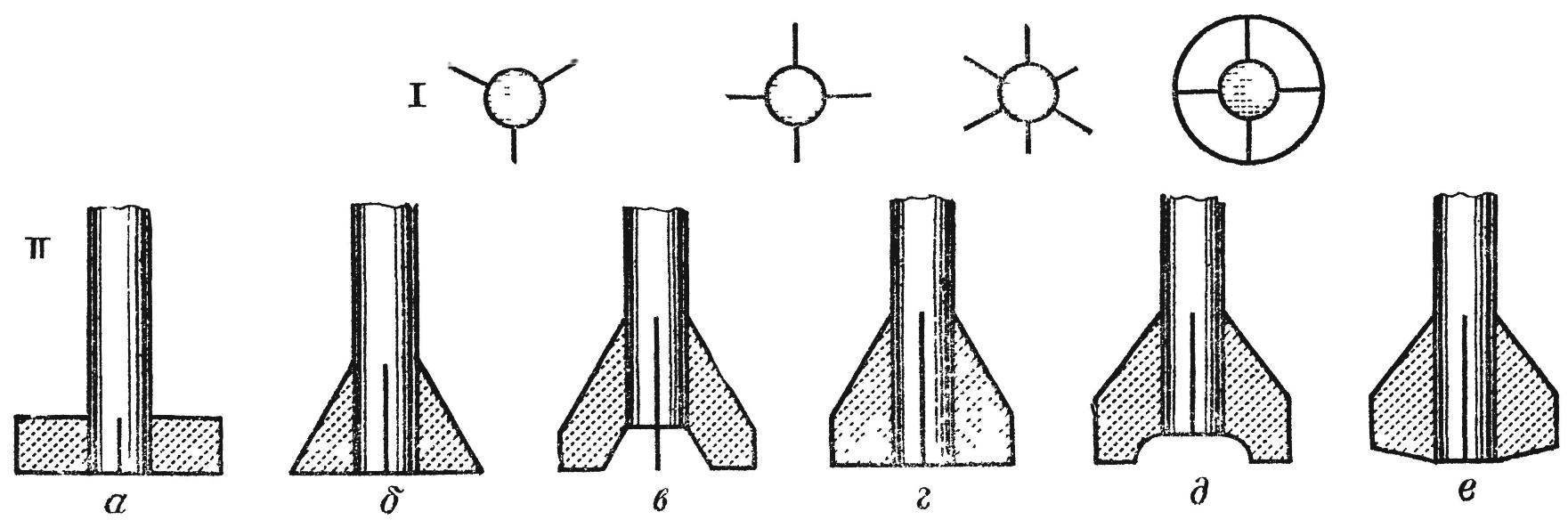
The shape of the stabilizers may be different (Fig. 1). The best stability of the model in flight provide are shown in figures 1B and 1D. They have about 40% of the area is cut aft (bottom) of the hull. However, other forms of stabilizers provide stability, because the elongation of the model λ = 15-20.
After choosing a stabilizer, make it a template from cardboard or celluloid. The template to cut the stabilizer out of plywood with a thickness of 1-1,5 mm or veneer (the smallest number of stabilizers — three). Put them in a pile (each other), secure a grip and treat the edges with a file. Then zakruglenie or sharpen all sides of the stabilizers, except that they are glued. Clean them with fine emery paper and glue to the bottom of the housing.
Fairing is desirable to carve on a lathe. If this is not possible, vystrugat his knife from a piece of wood or cut out of foam and finish with a file and emery paper.
As a rescue system used parachute, ribbon or other device. The tape was easy to do (see the description of the model of the rocket “Zenit”). How to make a parachute, are explained in detail.
The dome should be cut from fabric, tissue or mcalenney of paper or other lightweight material. Stick to his lines, as shown in figure 2. The diameter of the dome for the first models better to do 400-500 mm. Stacking is shown in figure 3.
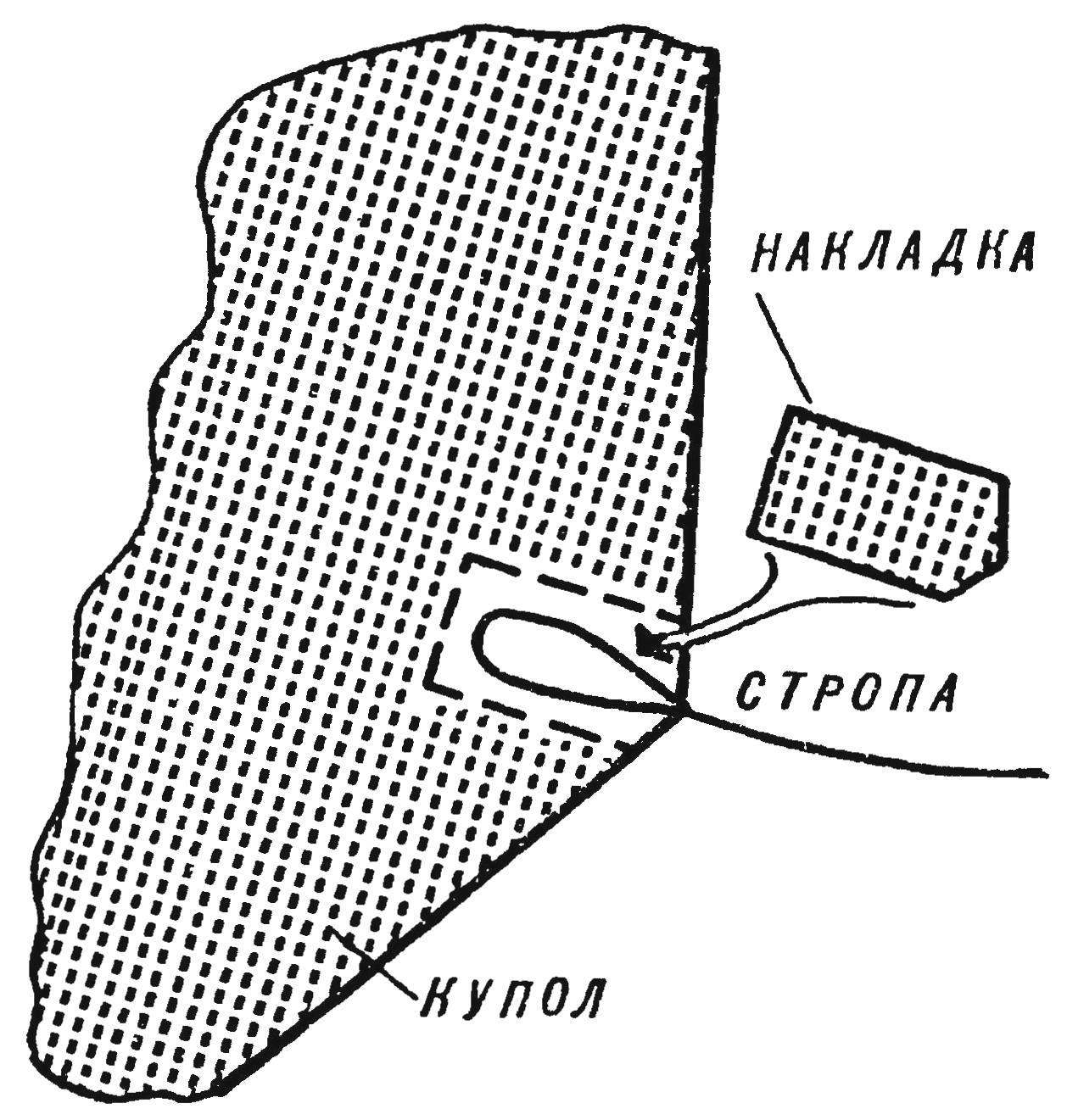
Fig. 2. The attaching of a sling.
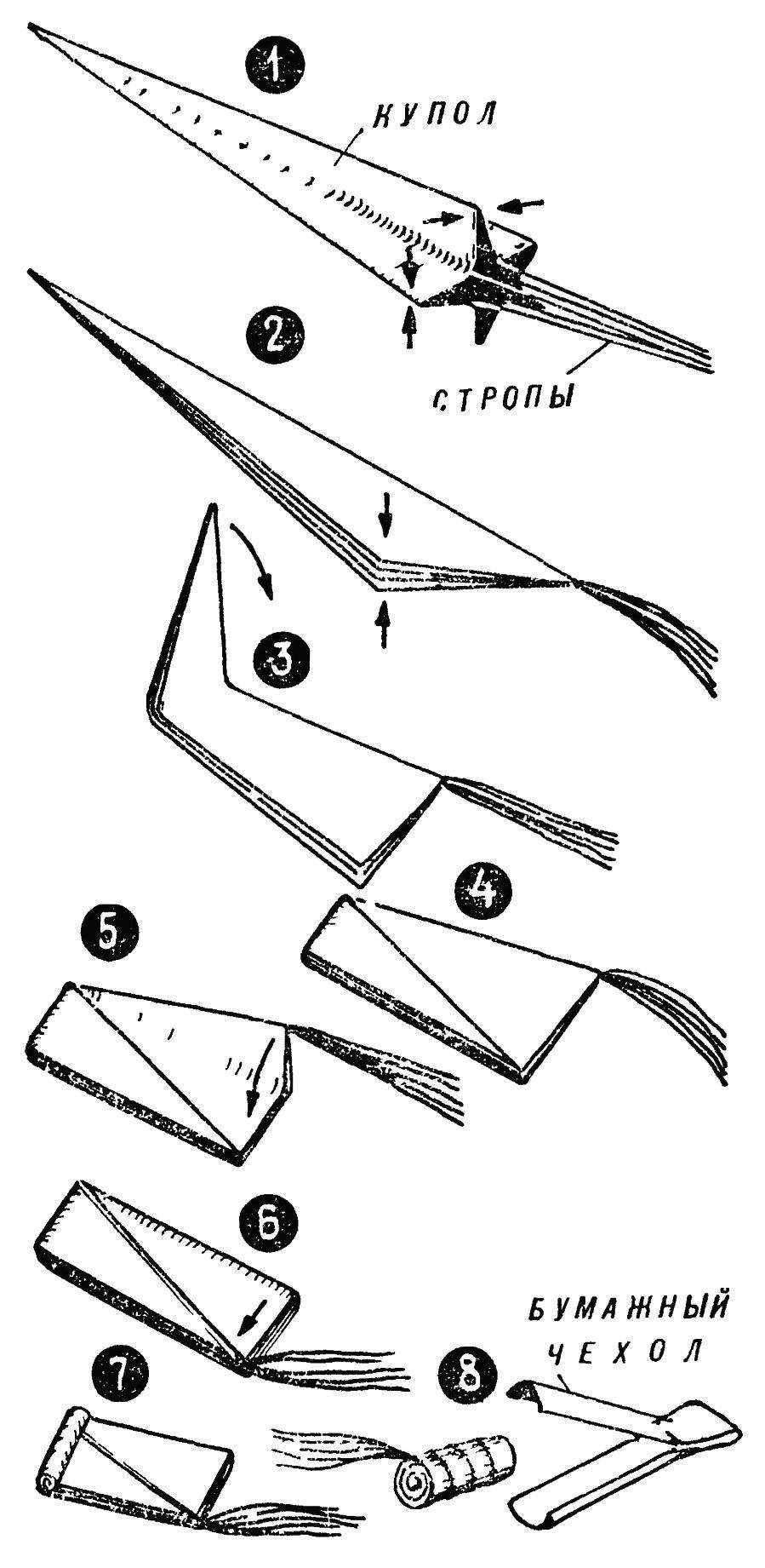
Fig. 3. Laying chute.
All the details models are ready. Now the Assembly. Fairing connect the rubber band (shock-absorber) with the upper part of the body of the rocket. The free end of the sling of the parachute clip on the head fairing.
To make the model easy to see against the sky, paint it in bright color.
Before you run the model, analyze its flight, let’s see whether our good first start.
THE STABILITY OF THE MODEL. One of the challenges as a big missile technology and small, is to stabilize — stability of flight along a predetermined path. The stability of the model is the ability to return to equilibrium is disturbed by any external force, such as a gust of wind. Speaking the language of engineering, the model needs to be stable in angle of attack. So is the angle, which is the longitudinal axis of the rocket with the direction of flight.
One of the ways of ensuring the sustainability of the model — aerodynamic — is to change the aerodynamic forces acting upon it in flight. Aerodynamic stability depends on the location of the center of gravity and center of pressure. We denote their respective TS. t and TS. D.
With the concept of TS. so familiar in physics lessons. Yes, and it is easy to determine, by balancing the model on the angular object such as the edge of a thin ruler. The center of pressure is the point of intersection of the resultant of all aerodynamic forces with the longitudinal axis of the rocket.
If TS. so the rocket is located behind the TS. D., the aerodynamic forces caused by changes of angle of attack under the influence of disturbing forces (wind) will create a torque that corner. Such a model will be unstable in flight.
If TS. located in front of T. TS. D., when the angle of attack of the aerodynamic forces will create a moment that will return the rocket to a zero angle. Such a model will be sustainable. And the more TS. D. offset C. so, the greater the resistance applied to the rocket. The ratio of the distance from the centre. on to TS. because the length of the model is called the stability margin. For rockets with stabilizers, the stability margin must be equal to 5-15%.
As noted above, TS. so models are not hard to find. It remains to determine C. D. Because the calculation formulas for finding the center of pressure is very complicated, we use a simple way of finding it. Sheet of homogeneous material (cardboard, plywood) cut out the shape along the contour of a model rocket and find TS. so this flat shape. This point will be the TS. D. your model.
There are several ways to ensure the stability of the rocket. One of them is the offset of the TS. D. to the rear of the model by increasing the size and location of stabilizers. However, on the finished model it cannot be performed. The second method is the displacement of the center of gravity forward by the weight of the head fairing.
After all these simple theoretical calculations, you can be sure of a successful launch.
Single-stage MODEL WITH a PARACHUTE (Fig. 4A). The proposed model can be recommended for competition for the duration of the flight.
The case of two layers of construction paper, glued with joiner’s glue on the mandrel with a diameter of 22 mm. At the bottom of fixed clip under the engine.
Guide rings from four layers of drawing paper, a mandrel for them is a round pencil with a diameter of 7 mm. Three of the stabilizer out of plywood with a thickness of 1 mm adhered nitrocream butt to the bottom of the hull.
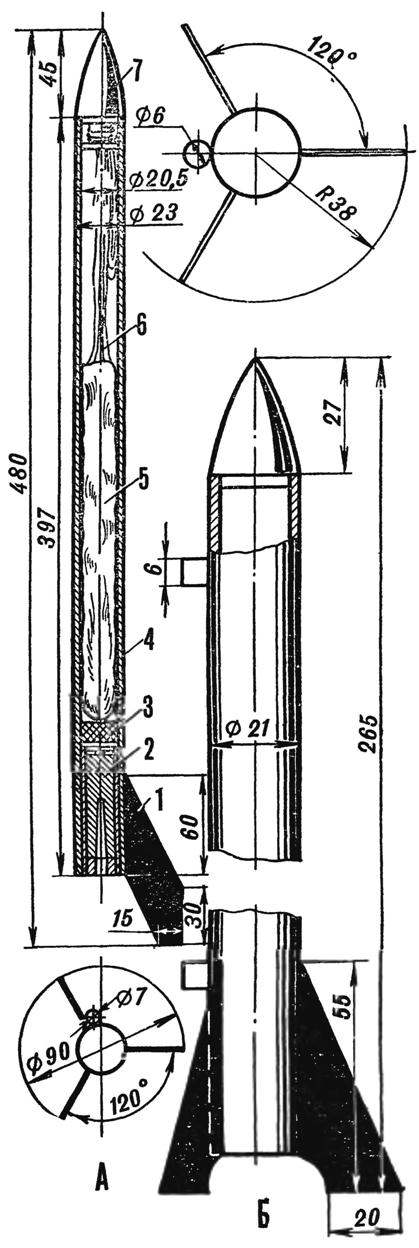
Fig. 4A. Single-stage model with a parachute:
1 — the stabilizer, 2 — engine, 3 — wad, 4 — body, 5 — parachute (without a case), b — slings 7 — fairing
Fig. 4B. Model for competition “trigger tape”.
Fairing machined on a lathe out of birch and is connected to the body with rubber thread.
The canopy is round, with a diameter of 500 mm, of mcalenney paper. Sixteen strop from threads No. 10 attached to the head fairing.
The entire model after Assembly is covered by three layers of nitrocellulose lacquer and painted by nitropaints strips of black and yellow.
Weight of model without motor 45
A MODEL ROCKET “ZENIT” (Fig. 4 B). This model is designed for competition “trigger tape”, and also on altitude.
The housing is glued paper on the mandrel to 20.5 mm. Stabilizers is made of plywood. Fairing is lime.
Tape size 50×500 mm made of mcalenney paper. One of the narrow sides by means of shock absorber (rubber filament) is attached to the body.
Weight of model without motor — 20 g.
V. ROZHKOV, master of sports of the USSR
Recommend to read
 YOUR BEST SCREW
Unfortunately, experience manufacturing propellers for the Amateur designs with rare exceptions not worth repeating. And perhaps the main cause of failures in the inconsistency of the... VAZ-2118 “the guelder-rose”
A new family of cars VAZ-2118 "the guelder-rose" is only the third in 35 years of existence, the Volga automobile plant — after "penny" VAZ-2101 and "chisel" VAZ-2108/2109 — really new,...
