 The carrier rocket “Cyclone-3”. Early 60-ies of the last century was marked not only by competition in space between the USA and the USSR, but a nuclear arms race. The first examples of Intercontinental ballistic missiles (ICBM), the Atlas in the US and R-7 in the USSR did not have a high readiness for use as an oxidizing agent with a low boiling liquid oxygen. The military of both countries felt the need to be armed with missiles that could be in constant readiness.
This was the impetus to the development of ICBMs on high-temperature propellants (nitric acid and its derivatives as the oxidant and the so-called hydrazines as fuel). In addition, these components of the fuel was self-igniting, which greatly simplified the design of liquid-propellant rocket engines, as they exclude the application of special devices for ignition.
The first such ICBM began in the United States “Titan-1”, a Soviet R-16. It was a two-stage rocket, which was carrying powerful thermonuclear warheads. Both missiles were close enough for mass-dimensional characteristics and design. Their further development became heavy ICBM next generation — USA “Titan-2” in the USSR R-36, are also very similar in size, payload and capabilities silo-based (finding a long time in a state of combat readiness, which is calculated by the minute). Both MRB served as prototypes for the development of families of space launch vehicles in their countries.
The United States used “Titan-2” for launching spacecraft “Gemini” and artificial satellites. For space launch vehicles (PH) does not need an increased readiness to start, and therefore, the use in them of low-boiling fuel components was appropriate because of the higher specific impulse. Later, the Americans developed a series of PH “Titanium-4”, which were equipped with 3rd stage “Centaurus”, working on liquid oxygen and hydrogen, and two solid-fuel boosters mounted large diameter. This would bring a payload up to 12 tons and more and to launch spacecraft (SC) to distant planets and even beyond our Solar system.
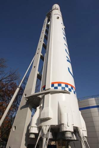
In the Soviet Union on the basis of the ICBM R-36 and R-З6орб. we developed a family of PH “Cyclone”. It is little known to our readers, as only in the “perestroika” years, this name appeared on the pages of the press. — And this is one of the most reliable collections PH of the middle class, using all the steps of the high boiling components of rocket fuel — nitrogen tetroxide (oxidizer) and unsymmetrical dimethylhydrazine (fuel). Because of the high toxicity of these fuel components for PH “Cyclone” was implemented the principle of “deserted” start with complete automation of pre-start training cycle and run. Launch complexes built for them on the Baikonur and Plesetsk.
The development of PH “Cyclone” was launched in Dnepropetrovsk design Bureau “South” under the leadership of academician Yangel in August 1965, by order of the government, providing for the creation of media based on a heavy ICBM R-36. This choice was not accidental — rocket escorting warheads into sub-orbital trajectories and orbits of the artificial Earth satellite.
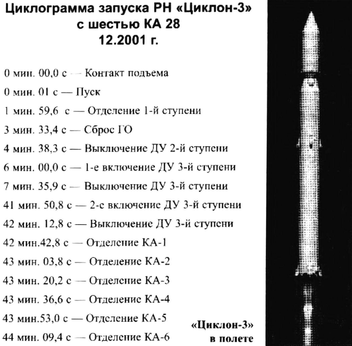
In 1966 and 1967 decree was amended and in accordance with it was created two versions of the media — two-stage “Cyclone” and “Cyclone-2”. Their flight testing began in 1968 At the end, a modified version of the “Cyclone-2” has become the main. At the same time they were developing and the three-stage PH “Cyclone-3”. Create media went hard, and was completed after the death of M. K. Yangelya under the direction of academician Vladimir Utkin. The first launch took place only on 24 Jun 1977 Flight tests ended with the adoption of the rocket-space complex with a PH “Cyclone-3” into service in January 1980, as of December 2002, made 120 runs of PH “Cyclone-3”, and of these only five were emergency.
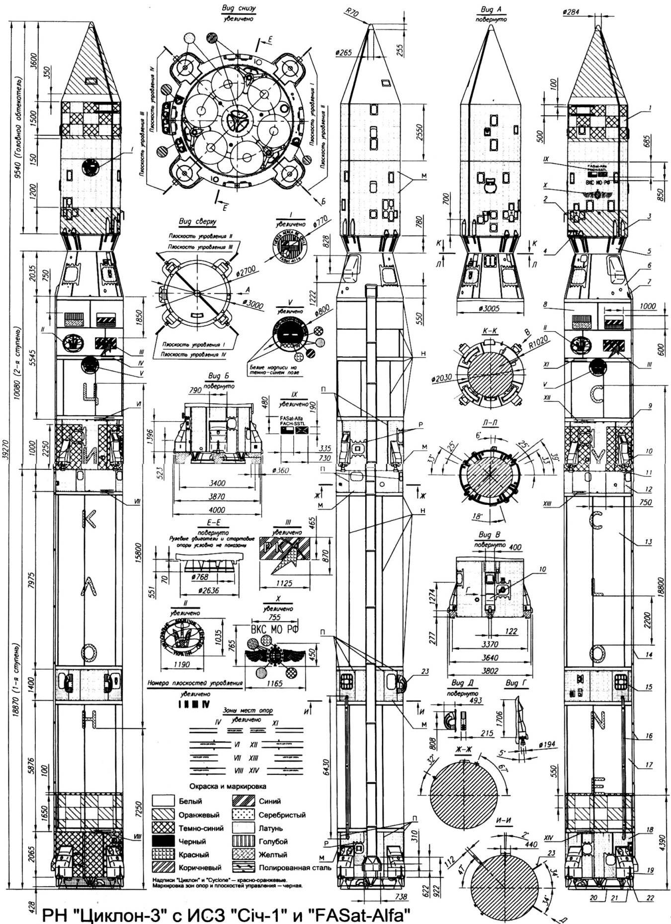
PH “Cyclone”:
1 — fairing; 2 — telemetry antenna payload; 3 — spring pushers; 4 — hinges; 5 — adapter payload; 6 — instrument section of the 2nd stage; 7 — telemetry antenna; 8 — cell 2nd stage; 9 — the rear compartment 2-tier; 10 — fairings; 11 — the steering liquid rocket engines of the 2nd stage; 12 — transitional compartment between the 1st and 2nd stage; 13 — oxidizer tank; 14 — gargrot; 15 — instrument otssc the 1st stage; 16 — small fairing; 17 — tank is flammable; 18 — caudal otssc 1-first stage; 19 — Radome; 20 — start-up support; 21 — steering LRE of the 1st degree; 22 — sustainer rocket engine 1st stage; 23 — telemetry antenna. M — seam riveted (rivets with hemispherical head): N — weld: P — chemical milling: P — overlap of panels
The first two stages of PH “Cyclone-3” and “Cyclone-2” almost completely unified and represent almost no alterations ICBM R-36. Division 1-St and 2-nd stage is available in “semi-hot” scheme — which is used for preliminary (before staging) start of steering engines of the 2nd stage. Division 2-nd and 3-nd stage — “cold” by means of four spring pushers.
The first step consists of a transfer compartment, the oxidizer tank, the instrument magbabago compartment, fuel tank and tail section.
The transition compartment is designed to connect 1st and 2nd stage. The construction is riveted aluminum alloy. It is formed by two end frames of the angular profile, the intermediate frames of the g-shaped profile and a longitudinal box-shaped stringers and T-shaped cross section. On the outer surface of the compartment there are four hatches. Powerful private profile stringers reinforce the structure at the locations of the hatches.
Tanks of oxidizer and fuel of a similar design. They are made of welded cylindrical shell, formed by six panels and two spherical bottoms. Inside the tanks are reinforced with longitudinal ribs, which are riveted with the help of fittings intermediate frames. In the upper bottoms are made manholes for access into the mounting vnutrividovoi fittings. On the bottom the bottom of the oxidizer tank is mounted the dispensing device of the disc type and the inside tank of fuel is its expenditure line. It is enclosed in a tunnel pipe, having a longitudinal corrugated ribs. Inside the entire length of the tank mounted six longitudinal radial partitions of the instigators of rest of the liquid. Material panels and bottoms — aluminum alloy AMg6.
The tanks are connected to the instrument compartment design is similar to the transitional. It has some instruments of control systems and telemetry. The same design has the rear compartment. It is located inside the propulsion system and the number of units of its hydro-pneumatic system. On the lower supporting frame compartment mounted four starting props and pneumatic, hydraulic and electrical connectors, to mate with a starting PH complex. On the side of the compartment are four cameras fairing with the steering liquid rocket engine (LRE). In addition, one of them being in control planes I and III, placed the rocket engine solid fuel (SRM) disposal stage after separation. Outside stage (under garrote) padded pneumatic and giprokommunenergo and cable network.
Power plant 1st stage consists of two engines — marching RD-261 and RD steering-855. Six-chamber LPRE RD-261 developed by NPO “Energomash” under the direction of academician V. P. Glushko. It is made by the scheme without afterburning of the generator gas and consists of three identical blocks RD-260, collected on a common frame with a single cable. Each unit has two combustion chambers, turbopump Assembly (TNA) with the frame, the replacement gas generator (GG), Firestarter for promotion TNA, the control units and pipelines. The dry weight of the engine — 1718 kg. the Diameter of the exit section of the nozzle is 768 mm.
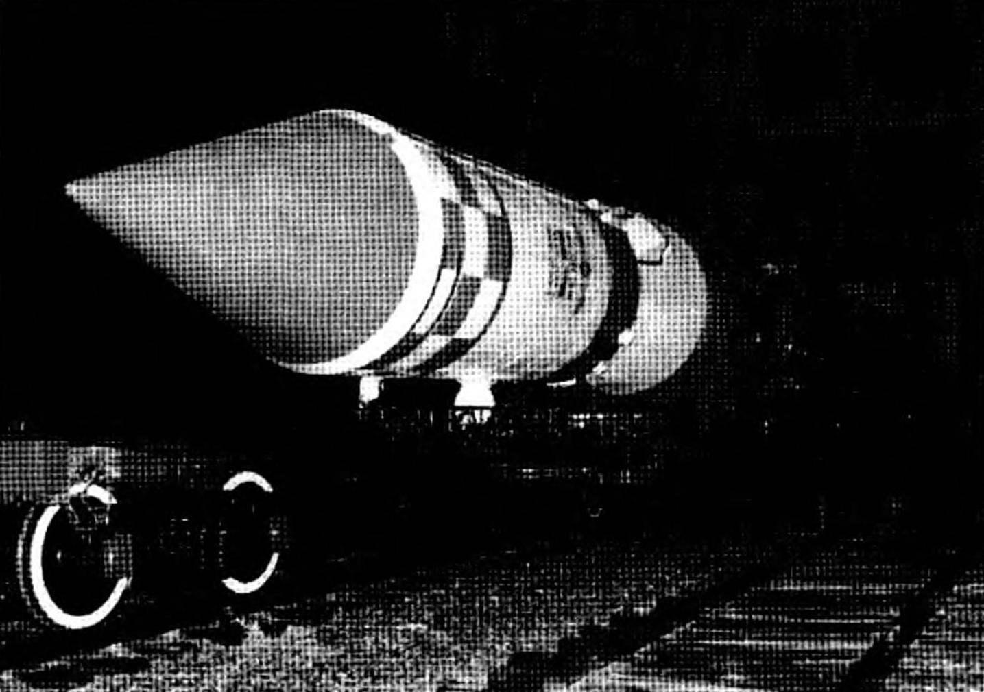
Export of PH “Cyclone-3” from Mika
Steering engine RD-855, development, design Bureau “southern”, also made by the scheme without afterburning. It includes four swivel camera (a rotation angle of ±41°), TNA, restorative GG, Firestarter, the control units and pipelines. Turn the cameras is carried out by hydraulic actuators. In addition, the engine includes oxidizing the PC and the mixer of fuel. They developed the hot gas is used for tank pressurization of the 1st stage. At the start the PH is first started the steering liquid rocket engines, the tank pressurization, and after about 2 starts marching LRE.
The second stage consists of an instrument, fuel and the tail section.
Instrument compartment riveted construction. It has the shape of a truncated cone. The outside is covered with insulation. There are four large hatch (one of which is closed by a fairing) for equipment maintenance management systems and telemetry.
The fuel compartment is formed by a cylindrical shell and three hemispherical bottoms — upper, lower and intermediate. The latter divides the compartment into two cavities — the oxidizer and fuel the Upper part of the shell is made of annular sections, and welded bottom of the six panels. Through the cavity fuel is a consumable, the pipeline oxidant. Inside the shell cavity of the oxidant is smooth, and the sides of the fuel cavity backed power set. The material of the shell and bottoms — AMg6. In the cavity of the oxidant also set the device for damping liquid from the top of the conical shell and with six radial partitions along a generatrix of the cylinder. Pressurization of the cavities comes from the special gas generators.
The rear compartment also riveted construction, which is similar to the caudal compartment of the 1st stage. It is a propulsion system and components of pneumatic and hydraulic schematic 2-tier. At its lower end the frame has a heat shield made of titanium alloy. Outside stages are electric and pneumatological, closed fairing.
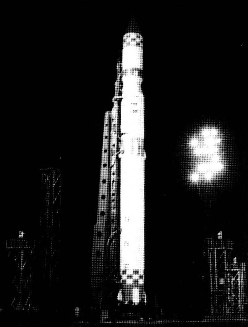
PH “Cyclone-3” launch pad
The propulsion system 2nd stage also consists of two engines — marching RD-262 and the steering of the RD-856. Marching RD-262, the development of NPO “Energomash” has two combustion chambers, turbopump, recovery GG. Firestarter, the control units and a number of other elements. The cameras are connected to a special frame on which is mounted turbopump, placed horizontally between the chambers in their critical sections. In fact, this rocket engine of similar design as the units of the main engine of the 1st stage, but is characterized by a nozzle with a higher expansion degree. The dry weight of the engine 665 kg, height 2.04 m, diameter 2.2 m.
Four-chamber steering engine of the 2nd stage RD-856, developed by OKB “South”, located identically to the steering motor 1 stage and similar in design. His cell closed four fairings on the side of the compartment. Under two of them, located in the control surfaces I and III, placed the SRB withdrawal stage. Also on the outer surface of the compartment has a filling neck. The axis of the combustion chamber rejected 5° relative to the longitudinal axis stage.
The third stage (to get the index C5) for PH “Cyclone-3” was designed specifically. It is equipped with rocket engine RD-861 (created by the design Bureau “southern”), working on the same components of fuel, and both lower level and allow for the double run. The third stage is joined with 2nd through transition compartment having the shape of a reverse cone, and is placed inside the cylindrical part of the fairing (TH). It consists of a frame, fuel and the tail section. To the frame located at the front of the stage and attached payload. The fuel Bay 3-tier is a toroidal tank, welded the outer and inner cylindrical shells and three bottoms — upper, middle and lower — alloy AMg6. Secondary divides the bottom compartment into two cavities — oxidizer and fuel. Inside cavities installed dampers oscillations of the fluid dispensing device and other fittings. In the volume formed by the inner shell, the frame is mounted sustainer rocket engine.
The RD-861 includes a combustion chamber, turbopump, the recovery of HS, two Firestarter, the system of emission gases, automatic devices and other elements. All units are mounted on a frame which is attached to the lower bulkhead of the tank of fuel. The system of emission gases, used in turbine, turbopump, provides flight control of the 3rd stage through the channels of pitch, yaw and roll. It consists of a flue, gazoraspredelitel (bypass valve) and eight fixed gas nozzles — four pitch and four yaw and roll Nozzle pitch and yaw are in the tail section and located at an angle of 35° to the longitudinal axis stage.
The rear compartment has the shape of a truncated cone and is designed to accommodate the Executive bodies of liquid propellant control system to their actuators. The control system is designed to calm the stage with the SPACECRAFT after separation, stabilization and orientation in free flight and the first launch of the main engine in space. It works on the same components of fuel and sustainer rocket engine and is an engine displacing feed components. The structure of this system consists of ten stationary miniature combustion chambers, fed from the main tanks, pocketcache elektrogeratebau, piping and mounting cameras. Eight of them are used to provide orientation and stabilization degrees on the pitch, yaw and roll, and two to produce axial overload before re-starting the sustainer rocket engine.
Fairing (made mostly of aluminum alloys). Its construction is riveted, formed of transverse frames, longitudinal stringers and longerons and a sheathing. On the lateral surface of the cone is made hatches for access and maintenance of the SPACECRAFT and the elements of the reset hinges and lifters. Fairing is reset to the phase of flight, 2nd stage, after passing the dense layers of the atmosphere, and is split longitudinally into two halves.
When creating a space rocket complex “Cyclone” introduced new approaches to the organization of works on preparation for start-up PH. This brought the domestic space rocket in the mid 60-ies of the last century to a new level. Suffice it to note that until recently in performance the complex has no analogues abroad.
On the proposal of the design Bureau of transport engineering, which was tasked with creating the launch complex, the basic missile R-36 was modified to adapt to the surface equipment. It will automate all main and many auxiliary operations. The level of automation cycle prelaunch preparation and launch of PH “Cyclone-2 and Cyclone-3” is 100%, but in General the works on the complex — at least 80%. The only dangerous manual operation is re-connecting gas communications in the case of the launch cancellation.
Technology features of the works carried out with the PH of the “Cyclone”, are as follows. After Assembly and carrying out the horizontal tests in the Assembly and testing facility PH is placed on a special Transporter-erector (TUA). It laid all the necessary communications to link the rocket with ground-based systems. Communications are connected to PH and to the Board, established at the end of the unit. It is equipped with detachable devices which when hitting and lifting TUA on the launcher automatically articulate with reciprocal connectors of the communication launch systems. In addition, part of the TUA and is a supporting ring, to which are attached the supports starting PH.
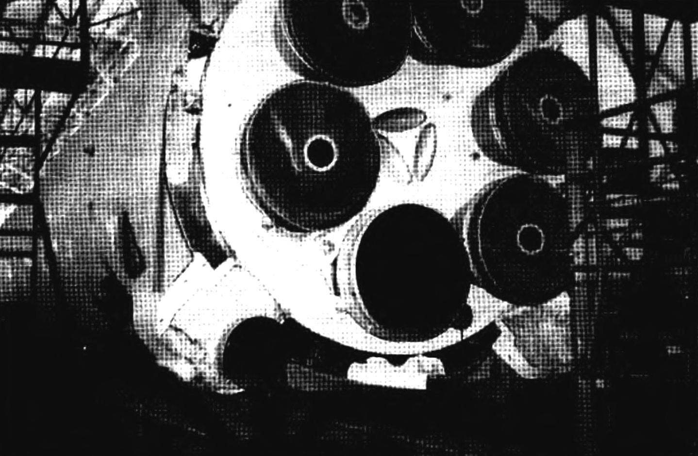
The propulsion system of the 1st stage (five nozzles worn covers)
Transporter-erector are transported to the starting table on the railway track and connected to the boom lift, which is part of the launch complex. Boom lifts TUA with PH in the starting table, and a support ring rigidly attached to it. The table consists of four legs and gototraining in the form of a hexagonal pyramid. After charging for 1 — 2 minutes before the command “start” is released from the PH of the grippers, lifting the boom with the TUA are given for 24° and the rocket launched. All combustible during start-up of products focused on TUA and removed from the starting position with him. The launch pad and other units do not require repairs after start-up. The whole process from a rise of the PH to the command “start” takes about 2 hours 30 mins Of them to the gas station spent only 15 min.
Launch complex “Cyclone” has the modern means of management and control. It is the first organized management process preparation and launch by a single program in a fully automatic mode, starting from the inlet PH to the starting table.
Currently, the design Bureau “southern” in accordance with the intergovernmental agreements between Ukraine and Brazil are working on the creation of PH “Cyclone-4” which will be a further development of PH “Cyclone-3”. It creates new, more powerful 3rd stage and the fairing is increased to 4 m diameter, and the first two stages remains almost the same as that of the “Cyclone-3”. The total length of PH will be 38,392. m. In the case of the project, in the Brazilian spaceport Alcantara, located near the equator, should be built to run complex PH “Cyclone-4”. Then PH can take a payload of 5.35 tons on orbit with altitude of 500 km with an inclination of 2.3°.
Recommendations for modeling
The carrier rocket “Cyclone-3” can be interesting for the experienced rocketmodeler as the object for modeling in the classroom S7 models on realism of the flight. Model-copy, built in three levels and acts as a prototype can get very high, approaching the maximum, the evaluation of the demonstration flight. This is due on the 1st tier of six model rocket engines (MRD), demonstrating a three-stage flight and perform the greatest possible number of special effects (reset the head fairing, double the burn of the 3rd degree, a separation of up to six layouts, KA, simulation pre-start maneuvering thrusters 1st stage). In addition, the simplicity of the launch pad, allows you are easy enough to model and do acting.
And while the prototype is fairly simple in outline, but has an attractive coloring and markings, which gives hope for a high enough bench evaluation. In addition, such a model-a copy never participated in competitions and will be completely new for the judges, and this will undoubtedly increase her rating.
Technical data PH “Cyclone-3”:
Launch mass, t…………………………………………………………….186
Mass of payload, t (on orbit with an altitude of 200 km)………….3.6
Length, m………………………………………………………………………..39,270
1st tier
Length, m………………………………………………………………………..18,870
Diameter, m………………………………………………………………………3,000
The maximum transverse dimension of the fairing, m…….4,000
The thrust of the main engine from the ground, kN……………………………..2459
The pressure in the combustion chamber, kPa……………………………………..8,66
The duration of the work……………………………………………120
Steering engine thrust, kN……………………………………………….297
2nd tier
Length, m………………………………………………………………………..10,080
Diameter, m………………………………………………………………………3,000
The maximum diameter of the instrument compartment, m…………………3,005
The maximum transverse dimension of the fairing, m…….3,802
Main engine thrust, kN ……………………………………………883
While working with………………………………………………………125 — 162
Steering engine thrust, kN…………………………………………….54,73
Diameter, m…………………………………………………………………2,700
Length, m…………………………………………………………………….9,540
The adapter length, m……………………………………………………..0,780
3rd tier
The thrust of the main engine, rocket engine kN…………………………………..81,8
The duration of the work……………………………………………118
When building a model I recommend to take design decisions taken for the model-copy PH “Space-ZM”, published in “M-K” № 8, 2000, Preliminary calculations show that useful for modeling the scale will be 1:40 to meet the maximum launch weight for model kits. The diameter-models will be 75 mm, and length is 982 mm. Starting weight will be 600 to 700 And then to run the model requires six МРД5-3 with a diameter of 13 mm, which will optimally fit into the dummy nozzle 1st stage. On the 2nd stage, it is sufficient to install one МРД20-6 with a diameter of 18.6 mm and 3-tier — one МРД5-3.
As the prototype has no tail, the main difficulty will be to ensure steady flight at all levels-models. For the 2nd and 3rd stage problem is solved by the use of drop-down stabilizers. The aerodynamic form of the prototype is that using download can not achieve necessary for sustained flight 1st stage the position of the center of gravity of the model, as in the case of the model-copy PH “Space-ZM”. Therefore, the 1st step it is advisable to apply a transparent stabilizers. Neatly done, the stabilizers will not affect the poster assessment will allow to avoid loading the nose of the model.
V. MINAKOV, engineer
Literature:
1. “News of cosmonautics”, No. 2, 2001, pp. 37 — 38.
2. “News of cosmonautics”, No. 2, 2002, pp. 41 -47.
3. “Cosmonautics news”, No. 11, 2002, pp. 52 — 54.
4. “Cosmonautics news”, No. 12, 2003, pp. 39 — 42.
5. “The Ukrainian rocket modeling”, No. 1, 1995, pp. 10— 14.
6. “The Ukrainian rocket modeling”. No. 2, 1995, pp. 8— 13.
7 First M. Missile systems of the strategic missile forces — “Equipment and weapons”, No. 5 — 6, 2001.
8. Putnicki V. Yu. and Domestic boosters. — SPb., Ed. center gmtu, 1996
9. Morozov, B., et Plesetsk Cosmodrome. — the city of peace, “international space center “Plesetsk”, 1992
10. Umansky, S. P. boosters. Spaceports. — M., “Restart Plus”. 2001
11. PH “Cyclone-3”. An album of drawings for rocketmodeler. Ed. by S. N. Konyukhov. — GKB “South”, 1996
Recommend to read
 SB
SB
In 1933 A. N. Tupolev proposed to make the Soviet analogue of "Martin". He undertook this task, but decided it differently. His ANT-40 in no way resembled an American bomber. For maximum...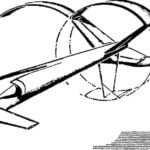 UNUSUAL LAYOUT
We all somehow got used to the fact that in the model aircraft competition "Experiment" most of the participants performs with apparatus of the type "flying wing". Today, however,...
