The widely used electric guitar inherited its tuning from its predecessor—the six-string Spanish guitar. The highest note that can be played on the instrument is usually E of the 3rd octave (for comparison: on the violin this note is E of the 4th octave, and on the piano—C of the 5th octave). On most electric guitars such high notes can only be reached with add-on devices—frequency doublers—which have not become widely used. The number of frets on the neck can also be increased. Some professional guitarist said in a TV interview that he had a luthier build him a guitar with 38 frets, but that is the exception rather than the rule. Production electric guitars typically have no more than 24 (often 22) frets, and their sound range is about 4 octaves.
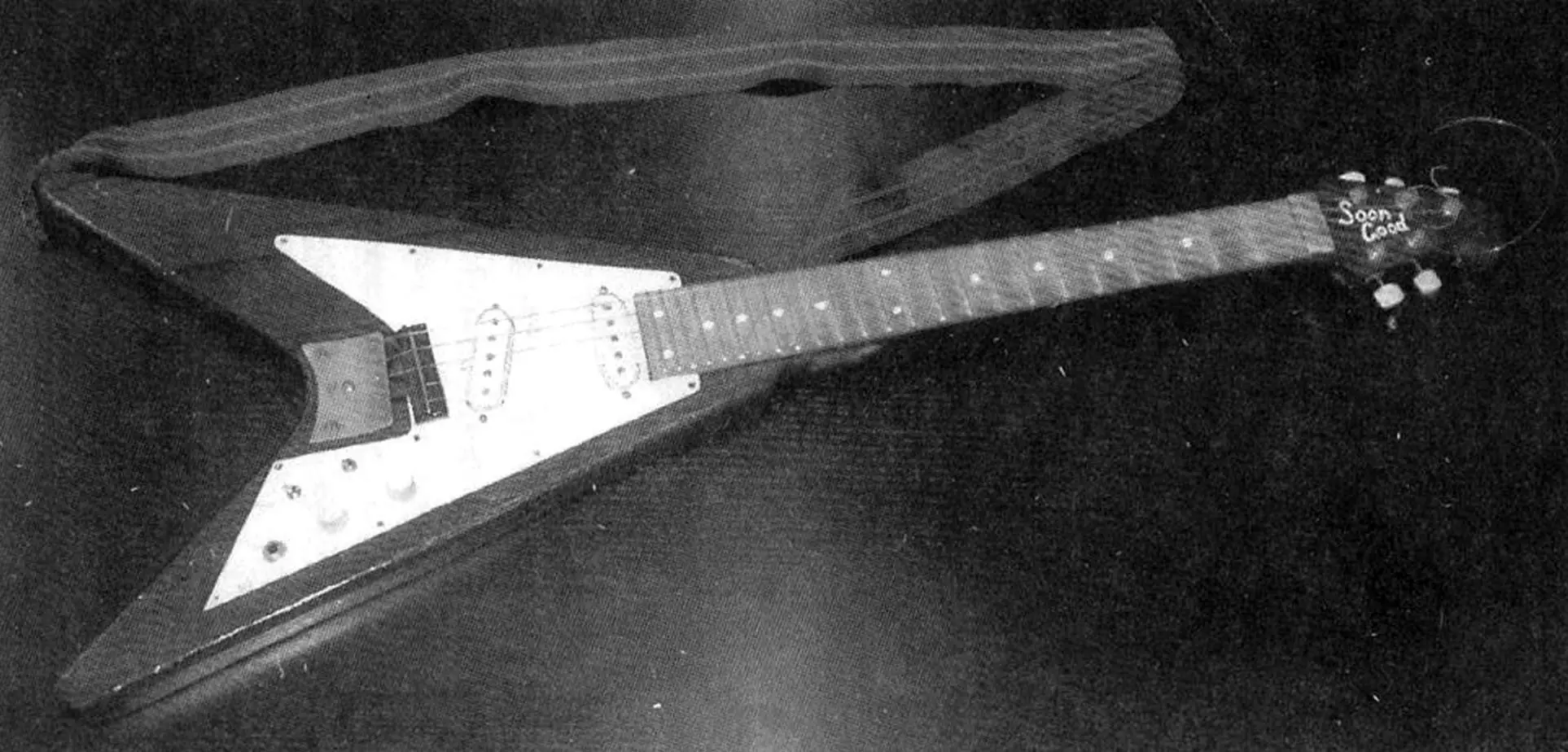
I present to readers the design of a 5-string electric “piccolo” guitar (from Italian—“diminished”), intended mainly for solo playing. Its range is 4 octaves, from G of the great octave to G of the 3rd octave. It differs from standard electric guitars also in its shorter scale (working string length)—546 mm instead of 650 mm—and in tuning: between the 1st and 2nd, and 2nd and 3rd strings the interval is a fifth (tuned at the 7th fret), and between the 3rd and 4th, and 4th and 5th—a fourth (tuned at the 5th fret). In my view, this allows a more even distribution of load across the four fingers when playing solos, especially on the first three strings. Standard electric guitars use fourths-and-fifths tuning.
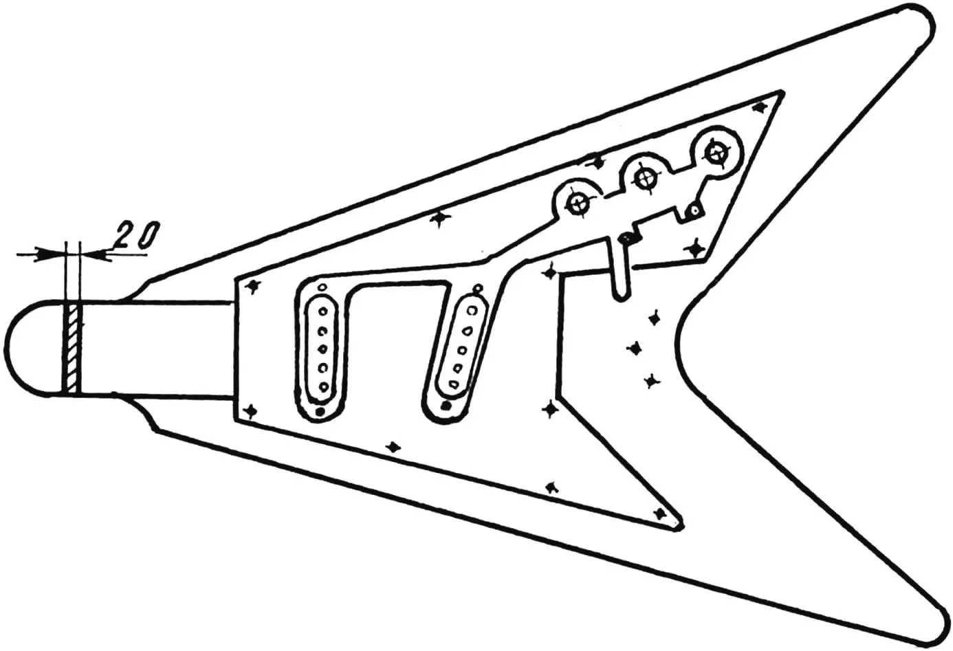
The electric guitar body is made from medium-hard wood. Maple is considered the best material, but spruce, birch, pine, alder, lime, ash or other well-dried quality board can also be used. The body may be glued from several narrower, carefully fitted blocks. Body thickness is about 40 mm (but may be from 35 to 42 mm), and at the neck joint it should be 20 mm. If the body is thinner than 40 mm, the depth of the pickup cavities in the body should be reduced accordingly and the bridge height increased.
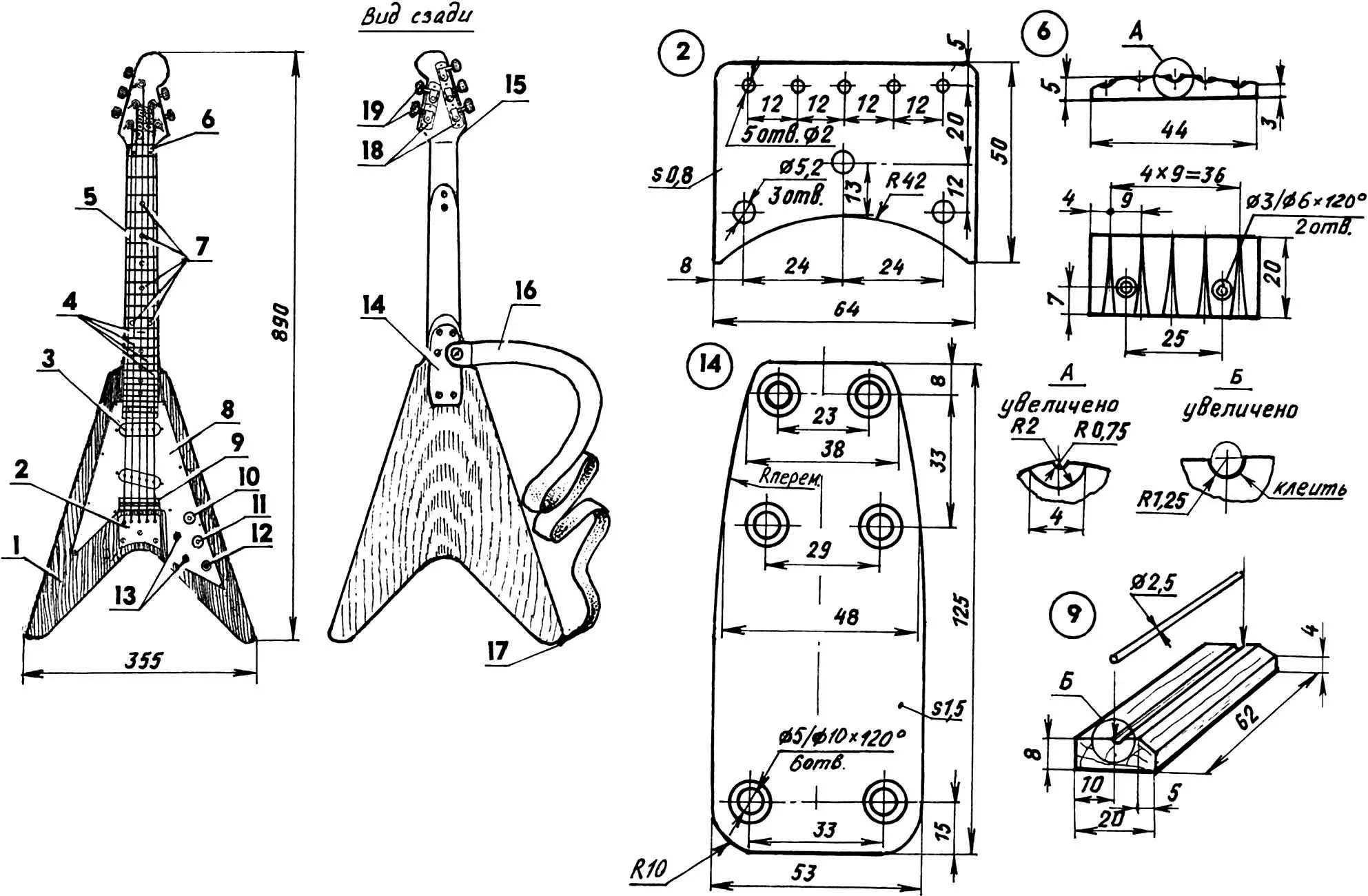
1 — body (hardwood, s42); 2 — tailpiece (brass, s0.8); 3 — pickup; 4 — strings; 5 — neck; 6 — nut; 7 — fret markers (12 pcs.); 8 — decorative pickguard (perspex s2.5); 9 — bridge; 10 — volume control (R1); 11 — tone control (R2); 12 — output jack; 13 — switches; 14 — plate (metal); 15 — headstock; 16 — strap (not shown on front view); 17 — strap button; 18 — tuner bases; 19 — tuner mechanism (from children’s guitar)
In the body, chisel out cavities for pickups (PU), wiring and other electrical components, and a cavity for the neck (chiseled to fit the existing neck); drill a 4 mm diameter angled hole for the wire connecting the tailpiece to the common ground. I used a neck from an old children’s guitar. I sawed off the stock headstock at the “seam” and fitted a homemade one made of birch in its place. The neck can also be made from very hard wood (ash, oak, maple); a drawing is provided. The headstock is attached to the neck with epoxy glue and two M5 flat-head bolts with nuts and washers.
The fingerboard is also made from hard wood, 7 mm thick, and glued to the assembled neck. It is then given a convex cross-section—curvature is greatest at the nut and gradually decreases toward the 24th fret.
Next, the neck is laid out. Note that in equal temperament the frequencies of two adjacent semitones (e.g. C and C♯) are in the ratio 1:2^(1/12), so the working length of the same string when fretting one fret higher shortens by a factor of about 1.04427. For example, if the open (unfretted) string length is 546 mm, the working length at the 1st fret is about 515.35 mm. Distances from the left edge of the neck to each fret are given in the table.
| Fret № | L (mm) |
|---|---|
| 1 | 30.64 |
| 2 | 59.57 |
| 3 | 86.87 |
| 4 | 112.64 |
| 5 | 136.96 |
| 6 | 159.92 |
| 7 | 181.59 |
| 8 | 202.04 |
| 9 | 221.35 |
| 10 | 239.57 |
| 11 | 256.77 |
| 12 | 273 |
| 13 | 288.32 |
| 14 | 302.78 |
| 15 | 316.44 |
| 16 | 329.32 |
| 17 | 341.48 |
| 18 | 352.96 |
| 19 | 363.79 |
| 20 | 374.02 |
| 21 | 383.62 |
| 22 | 392.78 |
| 23 | 401.38 |
| 24 | 409.50 |
Draw a centreline on the fingerboard with a sharp pencil. Then from the edge where the nut will be, mark the distances to the future frets (from the table) using a metal ruler (a tape measure can be used, but not from its zero) and a sharp awl. Then mark the fret lines with a square and a sharp pencil or awl.
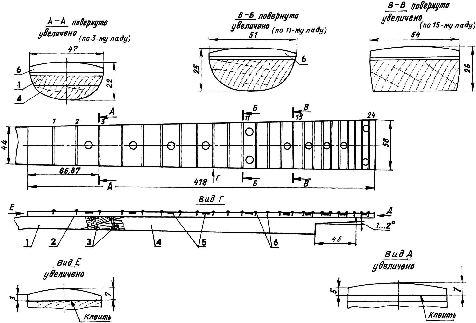
1 — headstock (hardwood); 2 — fingerboard (hardwood); 3 — M5 countersunk bolts with nuts and washers (2 pcs.); 4 — neck (hardwood); 5 — dots (white nitro enamel); 6 — frets (purchased)
My instrument uses frets 2.6 mm thick (2.5–2.8 mm, available from music shops, are also acceptable). Fret slots can be cut with a saw with slightly set teeth (a hacksaw or slotting saw is better). Frets are tapped in carefully with a hammer, filed, then removed and the ends dressed with a needle file to remove sharp edges. Then place one “dot” before the 3rd, 5th, 7th, 9th, 15th, 17th, 19th and 21st frets, and two “dots” before the 12th and 24th to help the player orient on the neck. Drill 5 mm holes 0.3 mm deep and fill with white enamel (nitro or PF-115 type). Then glue the frets in place with “Moment-1” adhesive. If a fret stands too high, level it with a hammer or file during final setup.
This instrument has a scale of 546 mm—about three frets shorter than standard electric guitars (650 mm). As the neck has no truss rod, medium or light gauge strings are recommended (sets where the thinnest string is 0.009 or even 0.008 inch at the same tension). Table 2 gives the open-string tuning notes and approximate string diameters.
Table 2
| String № | 1 | 2 | 3 | 4 | 5 |
|---|---|---|---|---|---|
| Note octave | G 1st | C 1st | F small | C small | G great |
| Diameter, inches | 0.009 | 0.012 | 0.022 | 0.031 | 0.038 |
The tuner mechanism is also from a children’s guitar. Drill holes in the headstock for brass bushings turned on a lathe for the tuners, so the headstock wood is less worn by the tuner parts. Other tuners for metal strings can be used, but then the spacing must be reduced by cutting the base plate between adjacent tuners and overlapping the parts. New cross-holes for the strings in the tuner shafts should be drilled to the same diameter. Grease the bushings with glue and tap them in. The tuners are fixed with 2×7 or 2×10 mm screws. The nut is made from steel or duralumin and fixed with two 2.3×13 mm screws on a wooden shim.
Pickup top plates are white furniture plastic, bases are from Paxolin. Each pickup core has 5 (one per string) 12.5 mm pieces of 5 mm diameter soft magnetic steel rod; even reinforcing bar can be used. To make it “magnetically soft”, anneal the stock—heat on a gas burner and let it cool to room temperature. Glue the core ends into the pickup base and top plate, wrap the cores with transformer paper (tracing paper or varnished cloth overlapping) and wind. Each pickup took 1200 turns of 0.1 mm PEW-1 wire. With 0.06 mm wire, 2000–2500 or more turns can be wound for higher output. Secure the winding leads to tinned 1 mm wire pins—insert them into 1 mm holes in the bases and bend into a loop. Then make the pickup shields. Side walls are single-sided copper-clad Paxolin, glued to the pickup with foil outward. Blank sizes: first pickup 45×12 mm, second 48×12 mm (2 each). Tin the blanks where the ground wire will be soldered. Without clad material, make these parts from unclad and glue copper foil on later. End pieces of the shields are 1 mm perspex, 28×11 mm (4 pcs.). Round them by holding over a gas flame or hotplate, then glue to the semicircular ends of the bases and apply copper foil with pre-soldered wire on top. Solder the four foil pieces so they form an open loop. Tie the shield to the pickup with thread and connect to one of the leads.
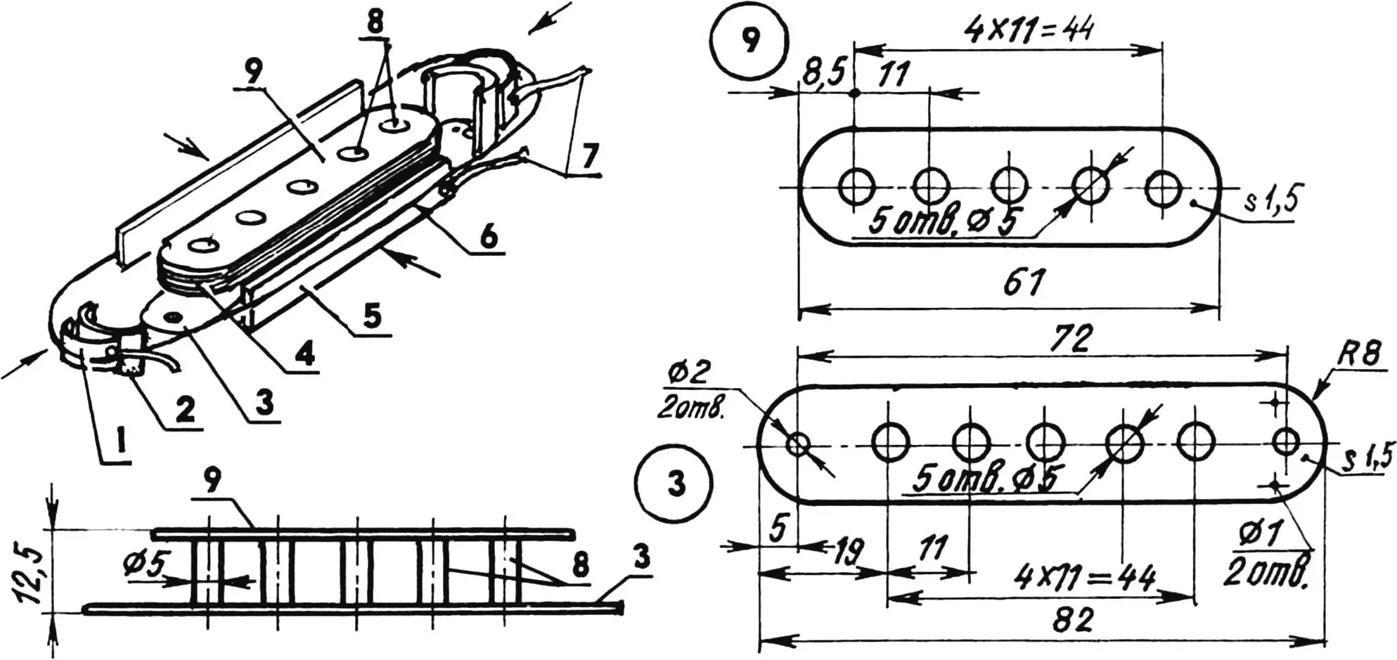
1 — overlay (copper foil, 2 pcs.); 2 — shield end (perspex, s1, 2 pcs.); 3 — base (Paxolin, s1.5); 4 — coil (PEW-1 copper wire, Ø0.1); 5 — shield side (single-sided clad Paxolin, s1, 2 pcs.); 6 — binding (thread); 7 — leads (copper wire, Ø0.5); 8 — cores (5 mm rod, 5 pcs.); 9 — top plate (white plastic, s1.5)
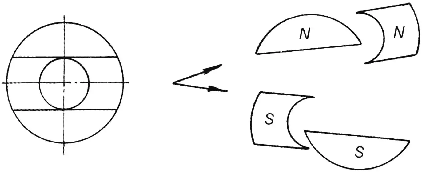
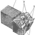
Magnets are from old loudspeakers. Mark each with a pencil into 4 parts, clamp in a vise on the line and split with a hammer. Then reassemble and glue the pieces under the pickups with “Moment-1” so they touch the cores and each other, and wrap with tape for security. The poles of one pickup’s magnets should point one way, the other pickup’s the opposite, so that with both pickups on you get hum-cancelling. The guitar uses single-coil pickups, which give better clarity than humbuckers for solo playing (though with lower output), especially with homemade pickups. Mains hum is greatly reduced by shielding, and the tone control in the circuit makes the speaker hum barely noticeable.
Pickups are connected inside the guitar to the rest of the circuit with shielded cable, with the shield grounded. A wire is also soldered to the back of the tailpiece and grounded—run through a dedicated hole in the body.
The decorative pickguard is 2.5 mm perspex. Complex-shaped holes for the pickups can be cut with a heated screwdriver or hot knife. After drilling, paint the pickguard on the inside with enamel (nitro or PF-115). Minor scratches on the perspex are fine—perspex painted on the back still looks much better than painted on the front.
Stain the body, headstock and back of the neck, then apply 3–4 coats of nitro lacquer (e.g. NC-243). The lettering on the neck is done with a pyrography tool and filled with white enamel after lacquering. When lacquering the sides of the body and neck, keep them horizontal for the first 15–20 minutes until the lacquer sets.
The circuit can be wired in two ways. In the first (scheme a) at least one PU is always on, but this needs more wire and is less reliable. The second (scheme b) is more reliable—beginners should choose it—but there is a switch position where no PU is active. SA1, SA2 are micro toggle switches; prefer SP3-30a resistors from groups B (R1) and A (R2); jack XS1 is for a 6.3 mm phone plug. Capacitor C1 is ceramic, H90 group. Connect the parts with shielded wire and ground the shield.
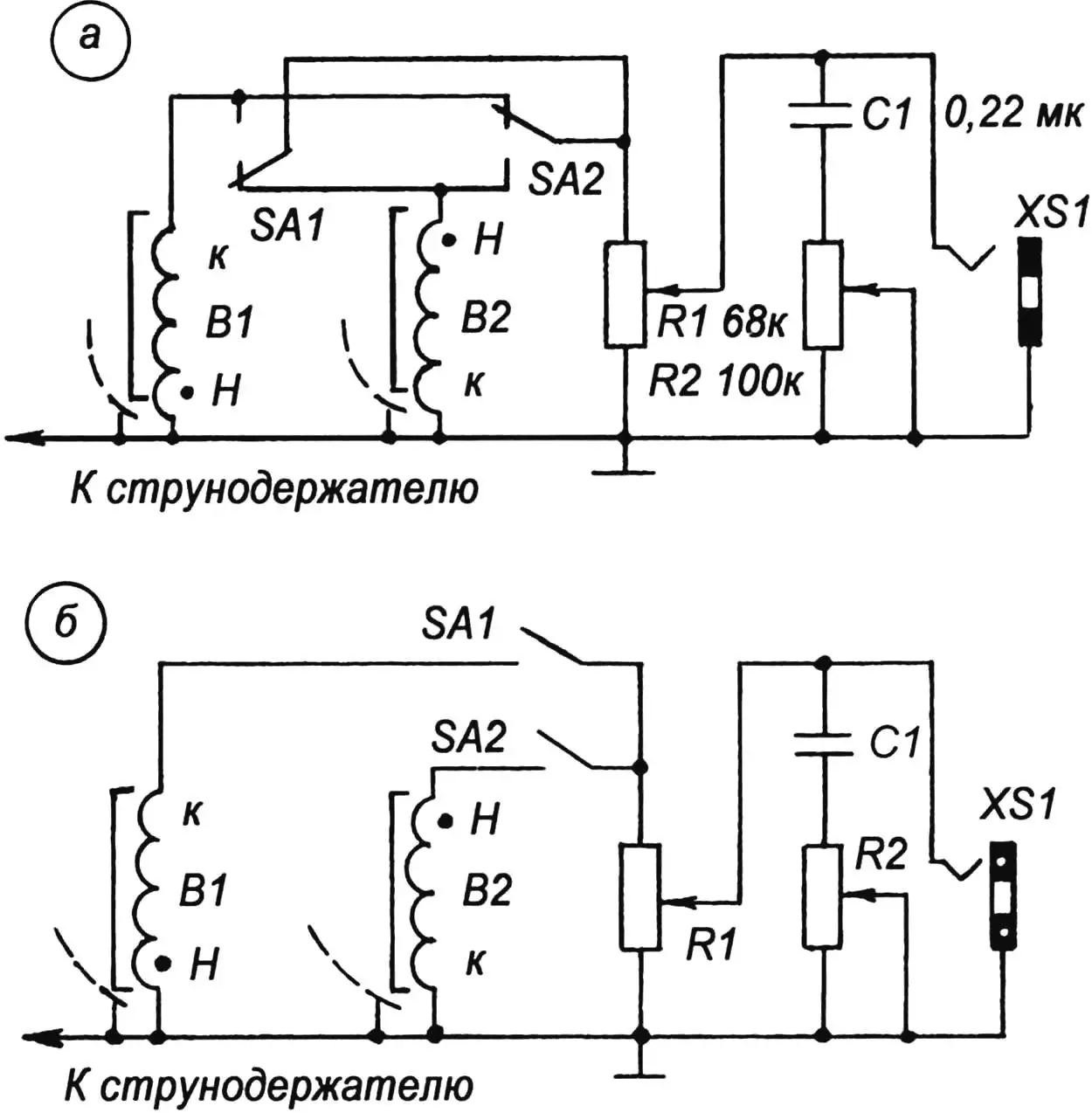
a) — at least one pickup on; b) — no pickups on
The bridge on this guitar is the simplest. Stain and lacquer the wooden part; the metal part is made from a 2.5 mm diameter nail with the head cut off and filed. Use the bridge to set the scale so that harmonics at the 12th and 24th frets match the fretted notes. A more complex bridge with per-string scale adjustment can be made if desired.
The neck is attached to the body with six 5×40 mm screws through a metal plate; it is tilted forward from the body by 1–2°.
Pickup bases are screwed to the pickguard with M3 screws, which are also used to set the optimal distance between pickups and strings. The pickguard is fixed to the body with 11×2×7 mm screws.
The tailpiece is attached with three 4.5×25 mm screws. By filing the back of the bridge or inserting veneer strips under it, set string height above the 24th fret to 2.5–3.5 mm, and with the nut about 0.6 mm above the 1st fret.
A 115–120 cm strap is attached with 5×40 mm screws; the strap holes are reinforced with leather pads.
I recommend periodically lubricating the tuner worm gear with machine oil. This greatly extends its life and makes string tensioning easier.
REFERENCES
1. Electric guitar. Radio magazine, 1969, No. 12.
2. Guzevich O.N., Medvedovsky D.S. Electric guitars. P., “Energiya” 1970.
3. Kukushkin V. Electric guitar. Modelist-Konstruktor, 1971, No. 10.
4. Sergovsky V. Electric guitar with melodic electronic channel. Radio, 1972, No. 1, pp. 45–48.
5. Guzevich O.N., Medvedovsky D.S. Electric guitar. Radio amateur’s aid. Radio, No. 42, pp. 55–66.
6. Ketners V. Electric guitar—organ. Radio, 1976, No. 1, pp. 45–48.
7. Guzevich O.N., Medvedovsky D.S. Electromusical plucked instruments. — L., “Energiya”, 1979.
8. Turakhin A. Electric guitars. Yuny Tekhnik, 1988, No. 2, 3, pp. 65–69.
9. Savinov N. Hum-cancelling pickup for electric guitar. Radio, 1977, No. 10, pp. 57, 58.
Modelist-Konstruktor No. 1’2006, A. BRANITSKY, Minsk, Belarus
Recommend to read
 CUTTER “PUSHPULL”
Remember PushPull fabulous animal which could jump not only forward but also backward, because instead of a tail he had a second head? About it can not help reminiscent of the original... A five-inch SHELL William McLean
The German engineers before the Second world war began the development of guided air missiles "air — air". Brought to flying condition samples and technical documentation "wonder...
