The model is quite simple and constructed with minimal use of balsa — it made the tail and fuselage to mid-wing. All other elements of the model is made of the most common materials — Linden, pine, cedar and aviation plywood. Going to epoxy glue.
The FUSELAGE — of the two symmetrical trusses-sidewalls. Each of them going separately from the strips section of 5X4 mm. Transverse kit fuselage 4 of the frame, sawed out of plywood with a thickness of 3 mm. Between the first and second frames is the fuel tank. Through these frames skipped two beech block motor.
Fig. 1. The design of the model:
1 — propeller Ø 275X135 mm, 2 — fuel tank 3 — lantern (glass), 4 — antenna, 5 — body, 6 — Kiel, 7 — rudder (balsa), 8 — “crutch” (wire), 9 — Elevator (balsa), 10 — stabilizer, 11, 13 — pins attaching the wing (beech), 12 — strut and the wheel main landing gear, 14 — stand and the front wheel chassis, 15 — motor mount (beech), 16 — rib (balsa), 17 — Polonnaruwa (foam) and 18 wing tip (foam).
Fig. 2. Docking halves of the wing spar with a plywood lining
Third, lightweight, the frame is mounted in front of the wing. Same frame and located behind the wing.
The raised sides of the fuselage are joined first, with the first and second and then the third and fourth frames. Between the top and bottom put an additional cross struts and braces.
After assembling the farm at the top of the foam fairing is glued to a semicircular cross section. The front part of the fuselage (mid-wing) is sheathed with plywood with a thickness of 1 mm, and the rear balsa veneer 1.5 mm thick.
The HOOD of the engine is removable; it is laminated from fiberglass and is secured by two screws to the bars of the motor.
STABILIZER. Its front and rear edges formed by the balsa rails cross section 5X10 mm. are glued Between the ribs (balsa rails with a cross-section 5X6 mm). The thus obtained frame is sheathed balsa veneer 1.5 mm thick.
KIEL. It is made Tocco the same way as the stabilizer. Rudders and height cut from balsa and light ply with a thickness of 5 mm.
The WING is single-spar. The spar is cut from Linden plates 3 mm thick and consists of two joined “the mustache” half; the connection is enhanced with plates of plywood with a thickness of 1.5 mm. the length of the plates coincide with the distance between the landing gear. Ribs carved from Linden veneer 1 mm thick and lightweight holes. Each of the ribs is reinforced shelves strips of pine veneer with a thickness of 0.5 mm. between the ribs are glued to polonaruwa of foam with a thickness of 10 mm. Front edge of the wing pine rail section 3,5X8 mm. trailing edge of the wing is solid balsa cross section 8X8 mm, reinforced on the top and bottom plates of the fake veneer thickness of 0.5 mm and a width of 5 mm.
Fig. 3. Hinge the rudder of PVC and its fitting with epoxy.
Figure 4. Installation of the steering machine
The wing box and center section are covered with cedar veneer with 0.5 mm thickness. wingtip foam.
In the middle of the wing is the well from dvuhmillimetrovy balsa plates — it is steering the machine. Strip of rubber substantially reduce the effect of vibration on her and allow tight to insert it in the slot.
The wing is glued with nylon, fuselage macalintal paper. The wing attached to the fuselage for the rubber rings are installed on the fuselage of a beech pin 0 8 mm.
The canopy is laminated of fiberglass and painted in blue. Landing gear from spring wire Ø 3,5 mm. wheel carved out of the PCB, and tires cut from microporous rubber.
The FUEL TANK is plastic, it Ø 53 mm. the pick-up tube rubber, end you’ll a weight of 4 g.
ENGINE model — “rainbow-7E. To reduce the vibration when the crankshaft further to balance, and the piston was made easier by the 2.5 g model is established by the air screw Ø 275 mm, step 135 mm.
The model is painted with nitrocellulose and covered antimetabolitam (parquet) varnish.
TECHNICAL DATA MODEL
Wingspan, mm — 1420
The length of the model, mm — 1122
Wing area, DM2 — 33
The surface of the stabilizer, DM2 — 8
Wing profile — NACA 2415
The relative thickness of the profile % -15 Angle transverse “V”, grad. — 6
Wing loading, g/DM2 — 70
The mass flight model, g — 2340
Alignment, % of MAR — 28
Setting angles, deg.:
wing is 1.5—2
stabilizer — 0
Engine — “Rainbow-7”
The deviation of the rudder, deg.:
height — ±15
directions — ±25
Aileron — ±20
Fuel tank volume, ml — 170
V. EGOROV, the head of the aeromodelling circle syut city of Kiselevsk, the Perm region.
Recommend to read MILL IN THE GARDEN His first motomizu A. Migranov built in 1981. As a prototype use if they had allowed themselves the development of his friend Peter Koynova. Although much was done differently: the... AIRBORNE PARAGLIDING Design truck for paraglider was preceded by just the fascination of paragliding, which did not come at once. First flew airplanes (and flight certificate), gliders. But one day, fly a... 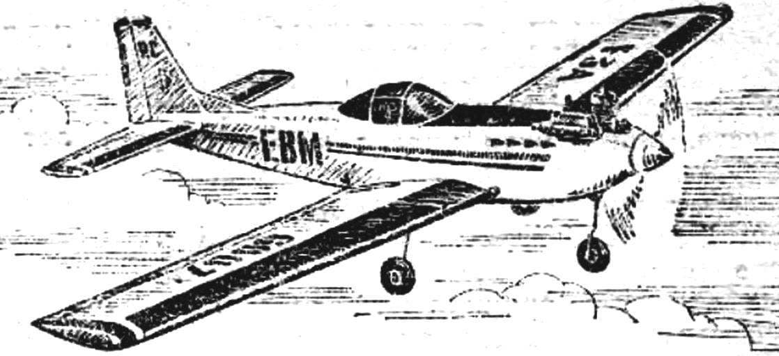
 For eight years I worked as a head of the aeromodelling circle at the station of young technicians in the city of Kiselevsk of the Kemerovo region. Himself in his spare time build a radio controlled model aircraft class S3A. I will provide the fellow training model aircraft aerobatic model.