
The metal detector I developed has not yet been used in peacekeeping operations to detect and neutralize minefields, nor in large-scale geological or archaeological surveys. Designed not for professionals, but for amateurs whose desire to “look underground” can be satisfied by a design with the parameters given in the table, it is an improved version of a “beat-frequency metal detector”.
The sensitivity of the device is increased due to the advantageous use (clear fixation) of the dependence of the probing pulse duration on the intensity of the sequences themselves with the introduction of automatic frequency control (AFC) into the search generator. Moreover, no additional measures were required to stabilize the voltage and temperature compensation of electronic units.
And the “irreconcilable contradictions” predicted by skeptics (they say, the change in frequency of the search oscillatory circuit when metal enters the working zone is incompatible with the normal functioning of the AFC system) were resolved by practice itself. It turned out that when moving the sensor over the surface under study at a speed of 0.5 — 1 m/s, the device circuit does not conflict with automatic frequency control, which has significant inertia (large time constant).
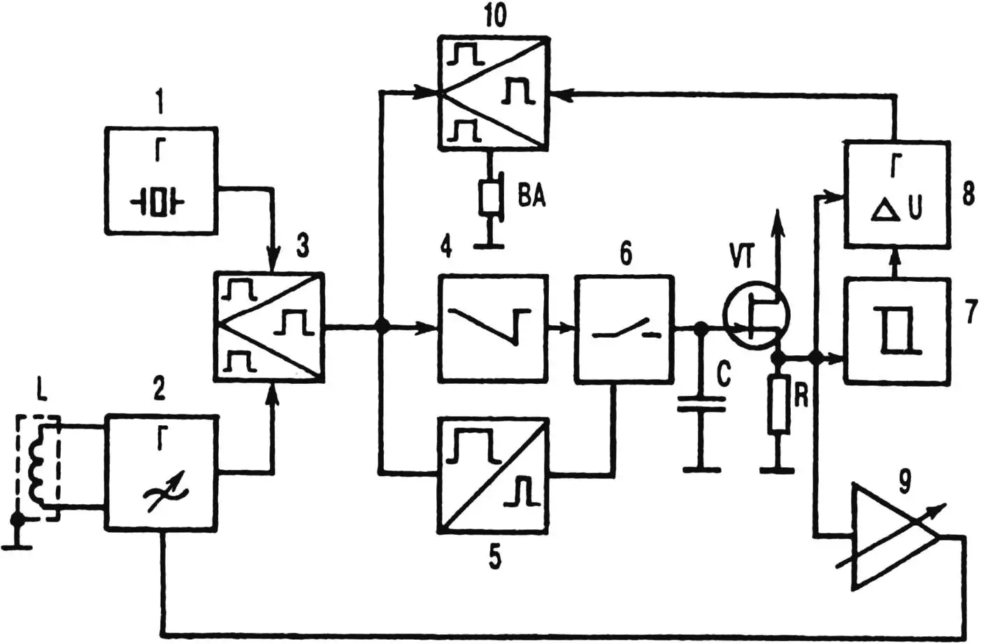
Already from the analysis of the block diagram, it is clear that manufacturing such a device is inherently more complex than any of the previous less sensitive analogs, including metal detectors published in issues No. 8’85 and 4’96 of the “Modelist-Konstruktor” magazine. After all, my proposed development, in addition to the standard set of reference quartz (1) and measuring (2) generators, remote inductance coil L (search frame-sensor), mixer (3) and audio recorder VA (telephone capsule), — has new devices that significantly improve operational characteristics. These are the integrator (4), which generates a sawtooth signal with an amplitude proportional to the control beat frequency, and the recording pulse shaper (5), which together with the key (6) and source follower VT represent an analog memory device that fixes the peak voltage from the integrator.
The metal detector is not without a comparator (7), which provides automatic switching of electronics from the zone of maximum sensitivity to the area of “one-to-one” beat registration (and vice versa), without a special VCO generator (8), which converts the voltage formed on the source follower into electrical oscillations with a frequency of 200—8000 Hz, as well as without the above-mentioned original automatic frequency control system AFC (9) with a special unit that slows down the device’s response to an excessively sharp change in the control voltage. There are also a number of other technical solutions here, among which, of course, one cannot fail to highlight the “operational amplifier” and special mixer (10).
As practice shows, it is precisely this composition of devices with the chosen method of forming an audio signal that allows listening to both frequencies simultaneously, significantly facilitating the initial adjustment of the device to a certain sensitivity. And the reliability provided is quite high. Even in an extreme situation, when, say, the search frame-sensor approaches a massive metal object at a distance at which the difference frequency becomes almost critical (70 Hz), no malfunctions occur — only the changing beat frequency is heard in the headphones.
Now about the details reflected in the principal electrical circuit. The reference generator is made on element DD1.1. Its frequency is stabilized by quartz resonator ZQ1, included in the positive feedback circuit. Resistor R1 serves to ensure generator excitation when power is turned on. The buffer element DD1.2 present here unloads the generator and also forms a signal with digital levels. Resistor R2 determines the load level and maximum power dissipated on the quartz resonator.
This generator can work with almost any resonators at a consumption current of 500—800 μA. And the frequency divider by two (element DD2.1) following it forms a signal with a symmetrical meander, necessary for normal mixer operation.
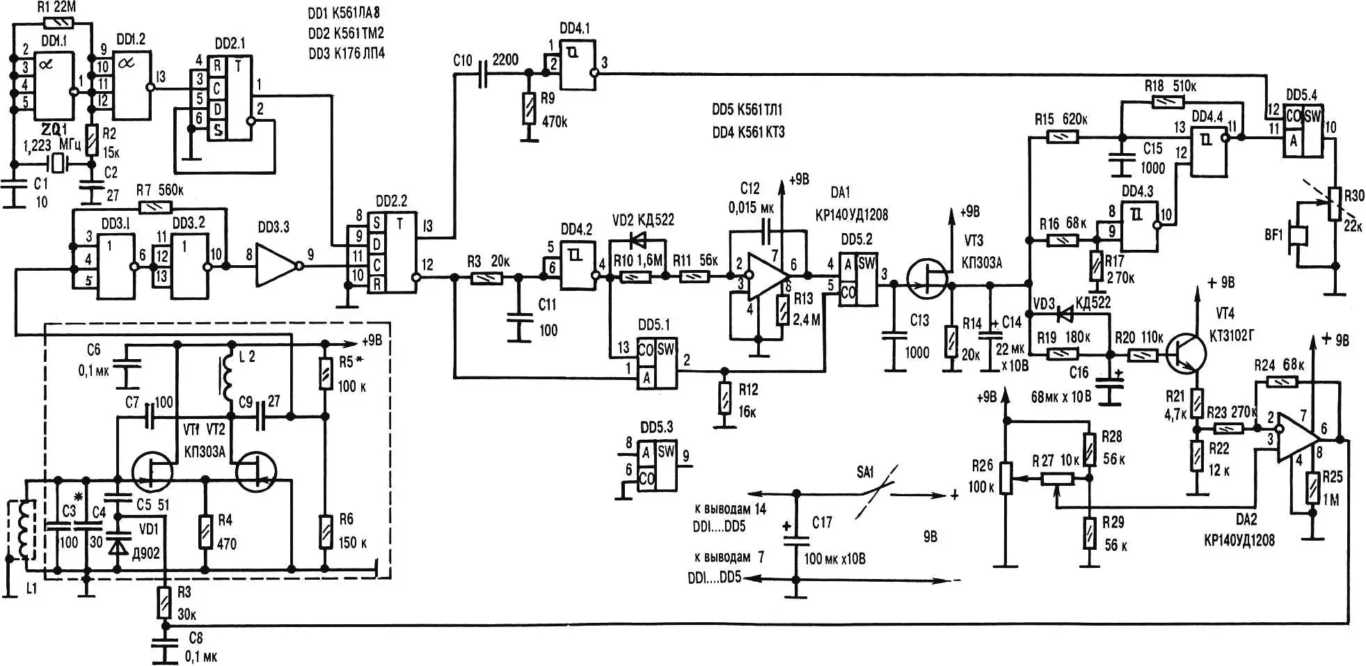
The measuring generator is assembled according to an asymmetrical multivibrator circuit (transistors VT1 and VT2). The positive feedback circuit on capacitor C7 ensures the transition to self-excitation mode. Frequency-setting elements are C3 — C5, VD1 and search coil-sensor L1. Moreover, generation is carried out in the range from 500 kHz to 700 kHz, depending on the available quartz resonator.
Such an important parameter as short-term instability in this generator is small. The frequency drift in the first 10 s immediately after turning on the power is no more than 0.7 Hz (and every 30 min — up to 20 Hz), although even 1 Hz per 1 min (without AFC) is considered acceptable for normal device operation.
The sinusoidal signal output by the measuring generator, having an amplitude of 1 — 1.2 V, goes through the decoupling capacitor C9 to trigger DD3.2, which forms rectangular pulses with digital levels and a duty cycle of 2. R5R6 is a divider necessary for normal operation of this section of the circuit. Well, DD3.3 performs the role of a buffer stage. The signal from it is fed to the mixer (T-trigger DD2.2). The frequency from the reference generator divider also goes there.
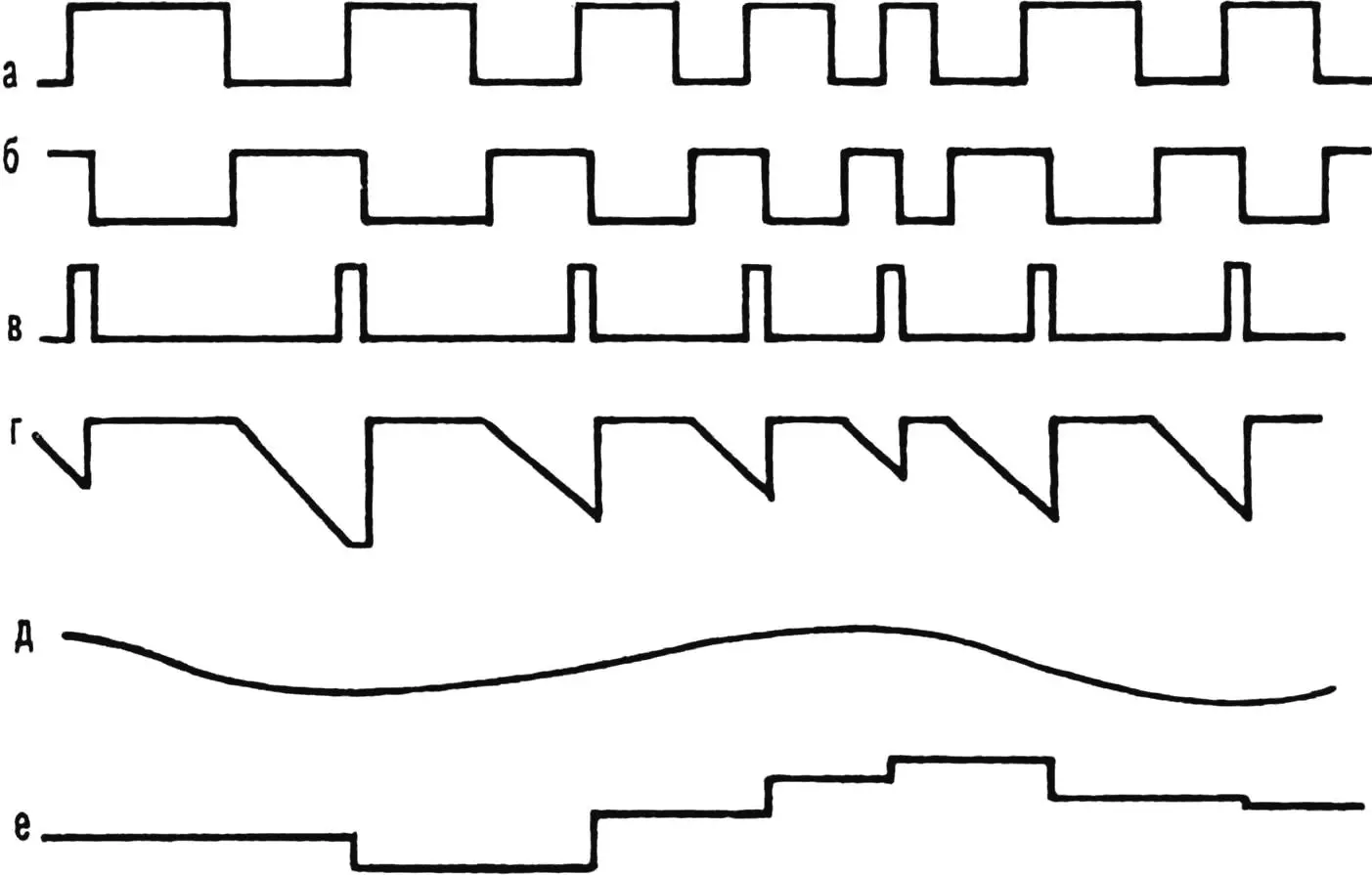
The features of DD2.2 operation are such that if two pulse sequences close in frequency come to inputs C and D of this logic element, then a difference frequency signal with a strictly symmetrical meander is formed at the outputs. Moreover, everything taken from output 12 of the mixer has the form shown in figure 2a.
Direct, as well as delayed (fig. 2b) inverted (thanks to circuit R8C11 and element DD4.2) signals are summed on key DD5.1, which performs the role of logical AND/OR with the formation of short positive recording pulses (fig. 2c) for the operation of the analog memory device (DD5.2, C13, VT3). But that’s not all. The signal taken from output DD4.2 goes to the integrator, made according to a classical circuit using VD2, R10 — R11, DA1, C12. Resistor R11 limits the recharge current of capacitor C12, unloading the output of element DD4.2.
The integrated signal (fig. 2d) through key DD5.2, controlled by pulses from DD5.1, is fed to memory capacitance C13, where a voltage equal to the peak value of what comes from the integrator is formed and held with high accuracy until a new recording cycle (fig. 2e). Capacitor C14 smooths out the “step” effect that can occur with a sharp change in beat frequencies (fig. 2f).
From the source follower, the signal goes to comparator DD4.3, VCO (voltage-controlled oscillator) and into the AFC loop circuit. Divider R21R22 together with R23 and R24 of feedback narrow the control voltage range to an amplitude of 1.2 V. Operational amplifier DA2 compares the obtained with what is set by divider R26R29, and forms the varicap VD1 control voltage.
Resistor R26 can be used to set the initial AFC capture point (sensitivity) roughly, and R27 — precisely. Moreover, when moving the slider of R26 towards the extreme (upper or lower according to the circuit) position, it is easy to exit the AFC capture zone (±300 Hz), implementing a mode with “one-to-one” beat frequency, which makes working with the device more flexible.
To understand the features of the unit that slows down the AFC response to a sharp change in beat frequency, let’s assume that on the base of transistor VT4 there is, for example, some established Uб. Let’s also assume that at some point there is a sharp change in beat frequency and, accordingly, voltage on C14. A working circuit of our metal detector will definitely respond to such an “input” with an adequate deviation of Uб of transistor VT4 from the previous value (thanks to large values of R19, R20 and C16). But the response to a smooth change in beat frequency will definitely be a reaction in the form of a slow change in the named voltages.
When a metal object enters the sensitivity zone of the search frame-sensor and stays there relatively long, a voltage is established on the base of VT4, which is usually sufficient to return to the set frequency mode. But when the sensor is sharply moved away, the situation changes, Uб of transistor VT4 cannot quickly return to the previous level. That is, conditions are created for crossing through “0” (occurrence of positive feedback). To exclude the latter, shunting of R19 with diode VD3 is introduced, through which rapid discharge of capacitance C16 occurs (return of Uб to the set level).
In fact, AFC has (depending on which direction the beat frequency changes) two time constants. And since the special design of the sensor practically negates the influence of ferromagnetic properties of detected objects on the increase in f of the search generator, both AFC and the device as a whole work very correctly in all modes. VCO (DD4.4, and R18, C15) converts voltage that changes with beat frequency into frequency. And the comparator DD4.3, adjusted using divider R16R17, allows it to do this in the zone of maximum sensitivity, when fбиений = 0…70 Hz.
The VCO frequency goes to input A of the mixer (key DD5.4). To input CO come from logic element DD4.1 both the difference fбиений, and a short negative pulse formed by differentiating circuit C10R9 (for better headphone sound, reducing power consumption). As a result, the mixer output contains either the fбиений-modulated VCO frequency, or only the beat frequency. Moreover, the circuit automatically switches from one mode to another. Variable resistor R30 serves as load and volume control, and SA1 combined with it — power switch.
The use of CMOS series microcircuits, operational amplifiers operating in microcurrent mode, made it possible to reduce the consumption current to 6 mA, making the use of a “Krona” battery as a power source acceptable.
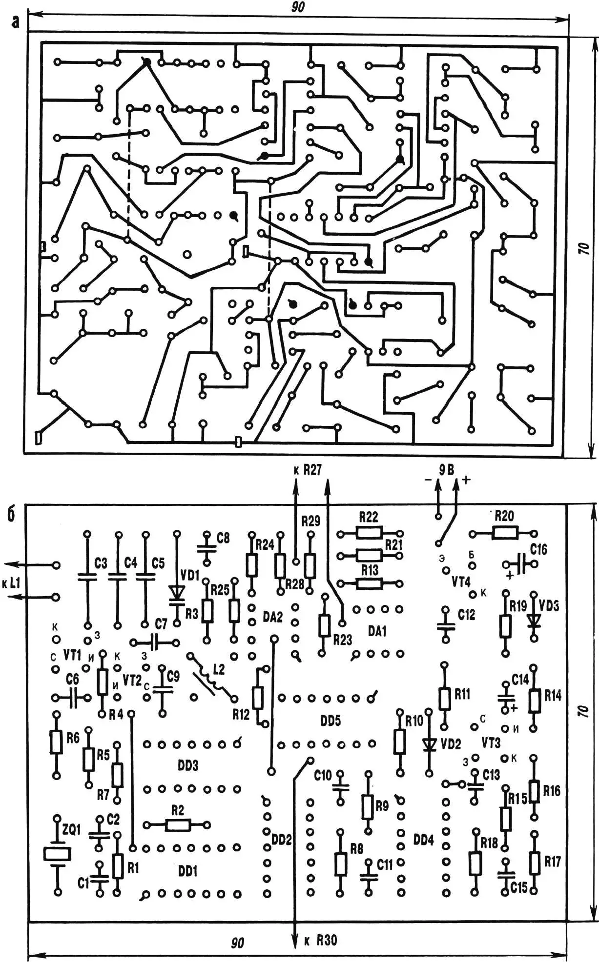
Like other analogs (including those published in “Modelist-Konstruktor” No. 8’89 and 4’96), almost the entire metal detector is mounted on a printed circuit board made of single-sided foil-clad fiberglass. The search generator is placed in a shielding box made of tin. Only adjustment resistances R26, R27, R30, power source and headphone connection sockets, as well as the frame-sensor, are taken outside the board dimensions.
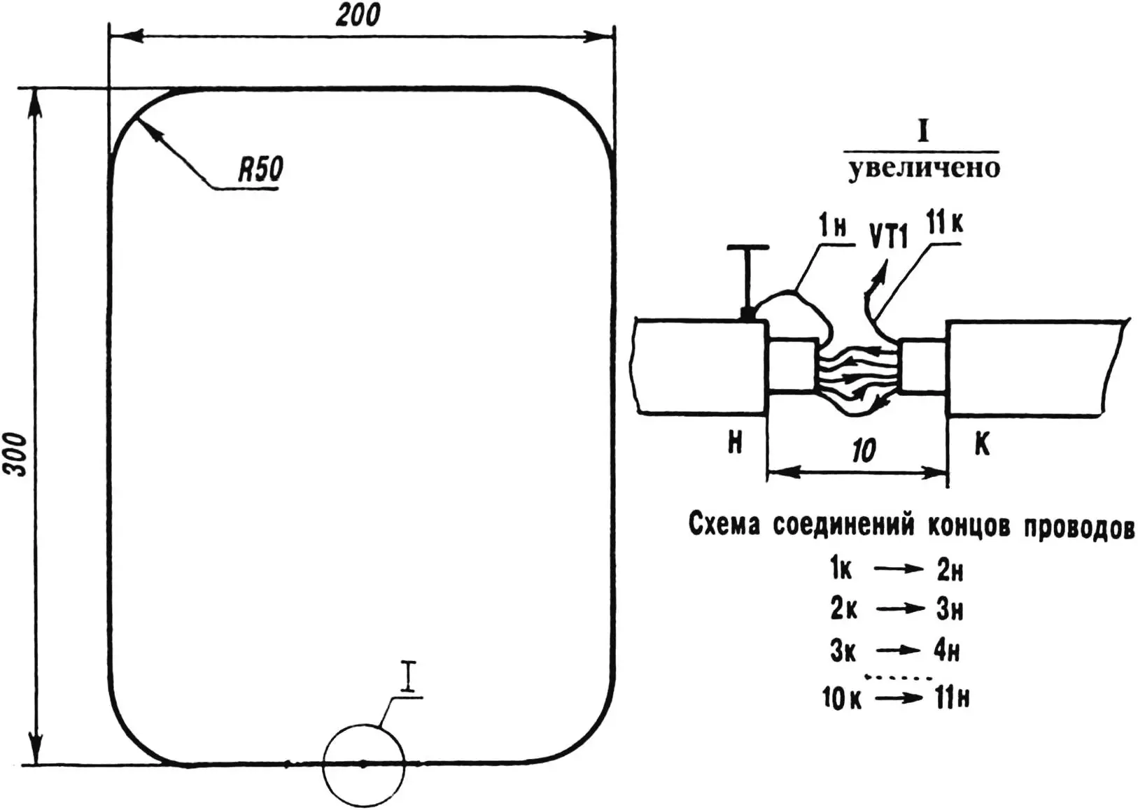
The technology and thoroughness of manufacturing the frame-sensor are so important for the operability of the entire metal detector that they require, apparently, a more detailed presentation. A bundle composed of eleven 1100-mm segments of ПЭВ2-1.2 wire is used as the basis here. Wrapped tightly with a layer of electrical tape, it is pressed into an aluminum tube having an internal diameter of 10 mm and a length of 960 mm. The resulting blank is given the shape of a rectangular frame 300×200 mm with rounded corners.
The end of the first of the wires, placed in the aluminum housing — electrostatic shield, is sequentially soldered to the beginning of the second and so on until the formation of a kind of 11-turn inductance coil. The joints are insulated from each other with paper tape and filled with epoxy resin, while excluding the appearance of a short-circuited turn due to the tube itself bent into a frame.
It is desirable here to provide any closed high-frequency connector and suitable (non-metallic) mounting for the rod-handle, which can use one or two sections from a collapsible fishing rod. The cable connecting the frame to the unit is better to use coaxial, television, for example, РК75.
Choke L2 of the search generator (designation here and further — according to fig. 1 and in accordance with the principal electrical circuit of the metal detector, published in the previous issue of the magazine) has 450 turns of ПЭЛ1-0.01 wire. Winding — random on a frame with a diameter of 4 and length of 15 mm with ferromagnetic core М600НН (you can use a suitable loop coil from an old radio receiver). The inductance of such a choke is 1 — 1.2 mH.
The device uses capacitors КСО or КТК (C3, C4, C5), КЛС or КМ (C1, C2, C6 — C13, C15), К50-6 or К53-1 (C14, C16, C17). There is also a choice of resistors. In particular, for “trimmers” R26, R27, СП5-2 or СП-3 will work. The same can be said about variable R30, only it must be combined with a switch. All other resistors are МЛТ-0,125 (ВС-0,125).
Digital ICs can be replaced with analogs from the well-proven К176 series. DD1, DD3 — any from the same series, as long as they contain the required number of inverters.
Transistors also allow replacement. As VT1 and VT2, for example, КП303Б (-Ж) will work. In place of VT3, КП303 or КП305 is acceptable (the letter index at the end of the name in this case does not matter), and КТ3102Г (VT4) will be replaced by КТ3102Е.
Quartz — from those designed for 1.0 — 1.4 MHz. The choice of headphones is also not limited. As practice shows, ТОН-1 or ТОН-2 will work quite well. Varicap Д901 can be replaced with Д902. Diodes VD2 and VD3 — КД522 (КД523) with any letter index.
To adjust the assembled device, an oscilloscope and …carefulness in work will be required. Having carefully inspected the entire assembly, power is applied to the circuit. Then the consumption current is checked, which in a correctly made working design should be 5.5 — 6.5 mA. When going beyond the specified values, errors in soldering, etc. are sought and eliminated.
The functioning of the reference generator is verified by the presence on pin 1 of IC DD2 of a frequency equal to 0.5f of the quartz resonator with a duty cycle of 2. Then they move to the “searcher”. Half the supply voltage is applied to the control point on the printed circuit board where R3 and C8 meet, while disconnecting the output of IC DA2. And with an oscilloscope connected to the drain of transistor VT2, the output voltage amplitude is checked. It should be from 1 V to 1.2 V. If the deviation exceeds 0.1 V, the number of turns in choke L2 is corrected.
And with the help of capacitors C3 and C4, the optimal signal frequency equal to 0.5f of the quartz is set. Moreover, the sensor itself should be located no closer than two meters from metal objects. If necessary, by selecting R5, they strive to obtain a symmetrical output signal on pin 9 of IC DD3 (while the mixer should output a difference frequency signal with a meander equal to 2). Then, having set the beat frequency equal to 8 — 9 Hz by changing the voltage on the varicap, the signal on pin 6 of integrator DA1 is measured — it should be “on the verge of lower limitation”. The corresponding correction is made by selecting the value of resistor R10.
Having connected the oscilloscope to the source of transistor VT3, the change in voltage level depending on the beat frequency is checked. With resistors R16 and R17, they achieve that a logical zero at the comparator output (pin 10 of IC DD4) appears only when Тбиений becomes higher than 70 Hz.
VCO is adjusted with resistor R15 so that the generator starts working when the integrator signal “exits from lower limitation”. In the future, this will significantly simplify device correction before work, since the minimum VCO frequency will correspond to setting the metal detector to maximum sensitivity.
Having restored on the printed circuit board the previously specially unsoldered connection of R3 and C8 with DA2, they proceed to the final stage of device debugging. The slider of “trimmer” R26 is turned to the extreme (“plus”) position, which will correspond to the maximum beat frequency (moreover, f of the search generator > f of the reference). Then, slowly rotating the slider in the opposite direction, they begin to monitor the signal on pin 6 of DA1. They notice how (at a certain position of slider R26) the moment of the signal entering the AFC capture zone appears on the oscilloscope screen.
Continuing to turn the trimmer resistor R27 knob, they achieve a beat frequency equal to 10 Hz, simultaneously checking the AFC operation (by the signal’s tendency to return to the initial state).
The sliders of resistors R26, R27 must be moved slowly, taking into account the large inertia of AFC. At the same time, the minimum VCO frequency and weak clicks with fбиений will be heard in the headphones. In some cases, a “floating” sound effect relative to some fixed state may occur. In this case, it is necessary to more accurately select the ratio of resistors R23, R24 or reduce the values of R19, R20.
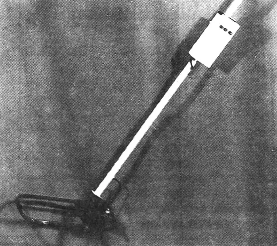
As already noted, the electronic part of the metal detector (and this is almost the entire device) can be mounted in any suitable housing mounted on a handle. It is necessary to ensure that the search frame-sensor, as well as connecting wires, are rigidly fixed relative to each other. After all, even minor vibrations of these parts that occur when the operator moves can cause a false signal (especially at maximum circuit sensitivity and insufficient experience working with the device). For the same reason, the shovel should be carried behind the back with the bayonet up (away from the frame-sensor). And metal tips on the operator’s boot laces are generally unacceptable. The interference they introduce threatens to negate all the efforts of the ultra-sensitive device to find in the ground what it so reluctantly parts with.
Working with a metal detector differs little from actions with a modern hand-held mine detector. Of course, such precise devices need adjustment. In our specific case — this is turning the trimmer resistor R26 slider to the extreme (“plus”) position, and R27 — to the middle. Having applied power to the equipment, the R26 adjustment knob is rotated in the opposite direction until a VCO signal appears in the headphones. After that, the trimmer resistor R27 sets the required sensitivity. And with the help of R26, they arbitrarily set (when working with the device in “one-to-one” beat mode) fбиений within 200 -300 Hz.
AFC and VCO are essentially disabled, so the search is conducted as usual. For clearer determination of the location of small objects, the frame-sensor is brought to the search zone either horizontally (with the rounded corner forward), or at an angle of 45 — 90° to the surface under study (with an obvious positional advantage of one of the frame sides).
MAIN PARAMETERS OF THE METAL DETECTOR
Printed circuit board dimensions, mm 90x70x2
Power supply voltage, V 9
Current consumed by the device, mA 6
Detection depth of steel objects in chernozem in established dry weather, mm
a) disc 10×2 mm 100
b) disc 100×20 mm 680
c) disc 500×100 mm (sewer manhole) 1400
Yu. STAFIYCHUK, Republic of Moldova
Recommend to read
 VITA — SWALLOW VELOMOBILES
Oddly enough, recumbent... older bike. Its ancestor can be considered the original "self-moving carriage" proposed by the famous Russian inventor Kulibin in 1791. On her back, at the... INSTEAD OF DRILL — FILE
Working with a file always takes a lot of time, particularly where its course is restricted: in a deep hole, in a curved channel. Here come to the aid of a power drill. Hold its...
