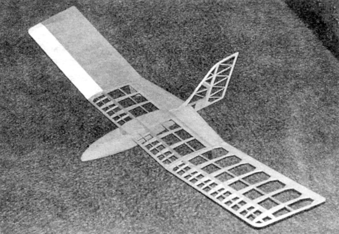
 The desire to populationat something unusual led to the creation of a very effective model of a glider of the type “flying wing”. The desire to “be different”, probably typical for any Modeler. Often this feeling leads to quite extraordinary decisions that could affect the development of a whole class of models.
But most often it is limited to unusual approach to individual nodes or to use unconventional design of the new device. Rather, to the last “design itch” refers to the decision to build a RC glider “flying wing”, at the time saboteure the author of this article.
In principle, nothing new in the “flying wing” is not available. It is also known that a “flying wing” proigrysha a bit for aerodynamic performance compared with the apparatus of the conventional “tailed” scheme. However… the desire to “be different” and create something “sort of” brought it to a tailless glider. Since originally designing unconventional technique fraught with failure, it was decided to first see what “doing” others. Search in domestic and foreign periodicals gave the desired result. Have found drawings and short description is very simple in design, but beautiful and spectacular glider Blackhawk (Black hawk). Among other things, was attracted by the information that the model was created by Keith Shaw – athlete with extensive experience in the design expense of building a traditional model. The experience allowed him to get a glider throwing type.

Even after intense throws, smoothly and with no loss of gained height the model is passed to the sustainable planning mode. Its distinguished and high sensitivity to rising thermals that very few gliders is typical of such schemes and scope. Successful was and the choice of modern self-stabilizing profile of the CJ-3309 has S-shaped middle line and sufficient relative thickness. Of course, it was intended that this model will retain all its dignity after mounting the tow hook to run through traditional lifelines.
Thus, the “prototype” to create a “flying wing” was selected. It remained only to reconstruct it in accordance with their own design ideals. Probably, the changes need to elaborate.
* * *
So, what has changed in the model, and saved in “original version”? The main power circuit, the profiling of the wing and the basic dimensions taken from a glider”prototype” with very few amendments. So, the shape of the wing tips has become more straightened to improve manufacturability and ease of design, and the fuselage acquired a broader millevoi section – for easy installation of radio.
The main changes made to the wing units, and a power circuit tail. Let’s start with the bearing planes. The new wing, despite relatively small scale, was split and now consists of three almost equal sections (processing design allows you to place all the parts of a four-foot wing in conventional plastic briefcase-“diplomat”!).


The fuselage Assembly. Lodgements servos and cover the nose compartment of the batteries is missing

Mount curly bracket (D16T) on the bulkhead with screws M3. Top shelf bracket with threaded hole M4 comes out on top of the fuselage

Lightweight celebarty keel with longitudinal reinforced of pine lath
Ladder diagram is modified to reduce mass – instead of a set consisting of two shelves of the spar and the walls now are only top shelf and the bottom of the power wall. The resulting light weight of the T-shaped profile has one glue seam and more logical for the wing, in flight, creating a positive lifting force. Instead of a pair of stringers in the area of the spout is left alone. Wingtip, made on the “prototype” in the form of large solid square shaped plates with a reinforcing triangular polynorborene, are now composing and, accordingly, much more light. Almost doubled the size of the gusset plate. On the consoles supporting the joints of the ribs with the back edge. Also to increase the rigidity of the ribs attached the balsa stringer section 3,5×3,5 mm, located on the lower surface of the airfoil between the trailing edge and the spar.
In addition, the replaced materials and the front edge of the stringer. Generally on the source machine I have used an interesting solution. Thus, the front edge it is made of round beech rods with a diameter of 5 mm, and both of the stringer from the same rails with a diameter of 3 mm. due to the lack of such products and desires to reduce weight, the flange was replaced by the almost triangular rail section mm 5×5 (hard balsa), and the only stringer is made of light balsa section 2×3,5 mm.
Update the tail of the model implies total replacement of whole plates of balsa patterned design, made of the same material. So, composing began as the tail part of the fuselage, and the keel with rudder. The Elevator (on the wing) for simplicity it is left without relief in the form of a solid balsa plates with triangular profile, its size is relatively small. Here it should be noted that on the original model the Elevator was in the middle only a thin slit which had been used as the fixed part of the keel. In the lowered position, the Elevator went to the top fuselage skin. In the flight situation in the area was formed wedge-shaped gap, which could not inure to the benefit of the aerodynamic quality of the airframe. Now, when half of the steering wheel at zero position are flush with the sides of the fuselage, the negative effects eliminated. By the way – the new version of the Elevator halves are not connected by a Central “torsion,” and are actuated through a forked rod. Although it is a matter of taste.
What is the result of design innovations? Despite the addition of four reinforced ribs and extra connectors of the wing, it managed to lighten the airframe by almost 20%! For models of this type is essential. Moreover, the developer claimed – the lighter the model the better (according to his recommendations, the glider should be in complete form no heavier than a 340 – 400g). Just say that the new design fully covered and partially painted model without the onboard equipment weighs just 210 grams, no more. Item: the center section of the wing with Elevator, 60 g, both detachable console – 40×2=80 g, the connecting pins of the wing – about 5 g, the fuselage Assembly with vertical tail surfaces and cover equipment 65,


Connector wing, front view. To the wall of the longitudinal ends of the flattened tubular “canisters” are fastened with M3 screws through the plywood strip. The input of the tubes cleaned, wrapped with a thin thread and glued in the root rib. All the joints of spilled epoxy. The root ribs have a pair of through holes for the passage of air

Wing connector, rear view. Visible plywood lining, reinforcing the root part of the spar

The structure of the ending (bottom view). In the nose of the ribs propylene holes for the passage of air in the rear for the same purpose drilled holes
A separate discussion deserves the choice obtainig material. First of all, it should be noted that the S-shaped profile offers minimal torsional loads on the wing in all flight modes. Therefore, it is possible to use any light material stitched. The proposed model lining was made of “composite”. The rear part of the casing, starting from the spar – branded “micuenta” paper. Unfortunately, there is no information on its name, nor the producer firm. However, this appears from time to time in our model stores, so it can be recommended for similar models. Its main symptoms are. First of all, this fiber paper is impregnated with the firm some colored (usually yellow or red) chemically resistant lacquer. Received obtainig the material is very lightweight and much more durable than normal micuenta paper Amalita. Gluing to the frame is conducted in liquefied “the Moment” or, much better, and cleaner, domestic “Desmosome” (sold in small tubes at most hardware stores), diluted with nitrobacterium.
Not strong, but very smooth stretch formed after Ironing it with an iron, which is used during the “welding” of the sheathing to the frame. Very importantly, the degree of tension of the paper does not change with time – a lot of the same usual brand of thermoplane “sags” just a week. The advantages of the said material must be attributed as the sustainability of the impregnating varnish to all solvents and some surface roughness. Moreover, the roughness has smoothed character, sufficient to improve the low-speed aerodynamic model of the airframe, and at the same time allowing easily to wash the contaminated portions of the model with soap and water.
I want to note that the use of conventional mcalenney or other long-fibre paper, impregnated with Amalita on this model undesirable. Although at first I had the idea to use this to improve the processability and rigidity of the wing, from this idea was then abandoned. The fact that the thin trailing edge under the influence of Amalita distort the shape, and it appear to “wave”.
The same applies to the whole wing. Over time, it is, especially at low relative thickness of the profile. Domestic same Mylar film creates not only a problem when pasting the same trailing edge (because of its large width), but with the tight upper rear part of the profile where there is a pronounced concavity. By the way, this concavity is, and on the lower surface of the wing.
The forehead is covered with white “Super Monokote”. He differs from other well-known thermoplanes high rigidity. We must admit – in the end, it became clear that this is not the best option. First, the material is glossy, and so I had to glue the stringer turbulators thread (illogical at the magnificent rough the casing of the rear part of the profile). The strength and stiffness of the film is clearly pereizbytochen (though someone probably will like it) when you increase the weight of the film. The race for increasing the rigidity of the wing in torsion could be won by the use of lighter materials. For example, a great result would replace the “Super-Monokote” Kraft paper, the imposed “wet” method on amalite. But, what’s done is done. The model still turned out very light and fly.


Set the main parts of the model before the end of the stitched
The fuselage, fin rudder, Elevator and cover of the instrument is decorated with thin colored thermal type “Solarfilm”. Here requirements obtienen material is limited to only minimal weight. The same film is made of decorative finishes.
Initially, according to the author of this article, the glider was equipped with standard equipment with standard steering servos (weighing approximately 50 g, with the same weight of the receiver). By the way – that’s why from the increased width of the fuselage. But later, the order appeared Hitec instrument with a miniature receiver with a mass of about 25 g and not too expensive but powerful and high-speed steering servo HS-80 weighing 18 g. searches for an appropriate power supply led to power Nickel-cadmium batteries Panasonic with a capacity of 300 mAh. The block of four of these elements weighs only 40 g (instead of typical 100 g). Can also try to put on a zenmuse h3-3d GoPro camera.
In the end side part of the control equipment in the amount of began to have a mass of 110 g, including all wires, plugs and the power switch. Takeoff weight of five-foot model was within the borders of 320 g. Here it is useful to note that the return to the standard equipment will increase the weight of the glider to only 420 g. This value is quite acceptable!
The rest of the airframe is quite typical, and detailed explanation is not needed. Therefore, it is possible to just debug the flight. Just note that any twist in the wing do not want to set – it should be smooth on the scale. Attempts to reduce inductive reactance due to the negative twist endings (very commonly used on most gliders normal scheme) is essentially meaningless – use the S-shaped profile initially causes a small lifting force and low intensity of the tip vortices. Even on a straight “flying wing” twist endings threatens to complicate and so a very critical balance.
It is the balancing – the most delicate moment in the adjustment of this model. As for any other Svobodnaya or radio-controlled “flying wing” with no sweep, the maximum difference of the alignment has a very small border. Therefore, we recommend beginning by moving the batteries and receiver to achieve the alignment shown on the drawings. Then, having made the field with tall grass a few test flights with the hands, try to move the center of gravity forward or backward in several stages (at one time – not more than 2 mm!). You will see that the flight mode changes quite active. In the result of debugging the glider during a low horizontal roll of the dice with his hands in the wind should fly about 30 m. After this, you can try to make a run with a strong throw at an angle of about 45 to 50° to the horizon and see how smooth is the transition to the normal planning. If there is a tendency to oscillation of the model in pitch, slightly slide forward the center of gravity.
The next step is to debug a take – off on the guard rails. From the start use the Leer normal length. Cropped Leer not only distort the nature of the behavior of the glider on takeoff, but will leave much less time for making the right decision. It is important in the process of adjustment to find the ideal position of the tow hook. And it will have to do as carefully as to align the model. Take some time on this process.
As a result, you’ll be surprised how much it is reliable and easy to run. The flight properties of this small glider after proper debugging make you forget about the fact that the quality of planning a “flying wing”, in principle, the model loses the usual scheme.
In conclusion, some interesting information. According to foreign magazines, Blackhawk airframe like many foreign modelers. And, in addition to the clean copy of the reference design, they have already established a larger modification of the airframe, a wingspan of up to 2,500 mm. Maybe this way will be of interest to you? Then literally one piece of advice-use our drawings for the revised model, and modify the scale in any ratio. Exactly in the same proportion will need to be increased and the sizes, thicknesses, and cross sections of all parts. This will guarantee sufficient strength of all elements. The flight is the same quality as known, the increase in the size of the model can only improve!
UTONOM K., candidate of technical Sciences, Novosibirsk, Russia


