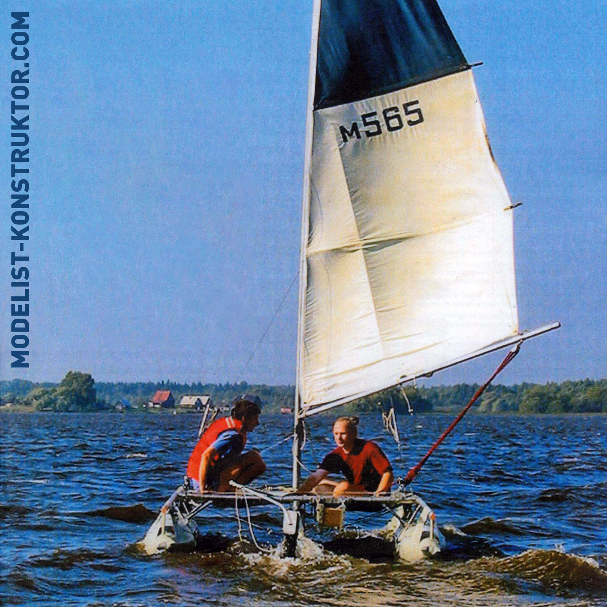
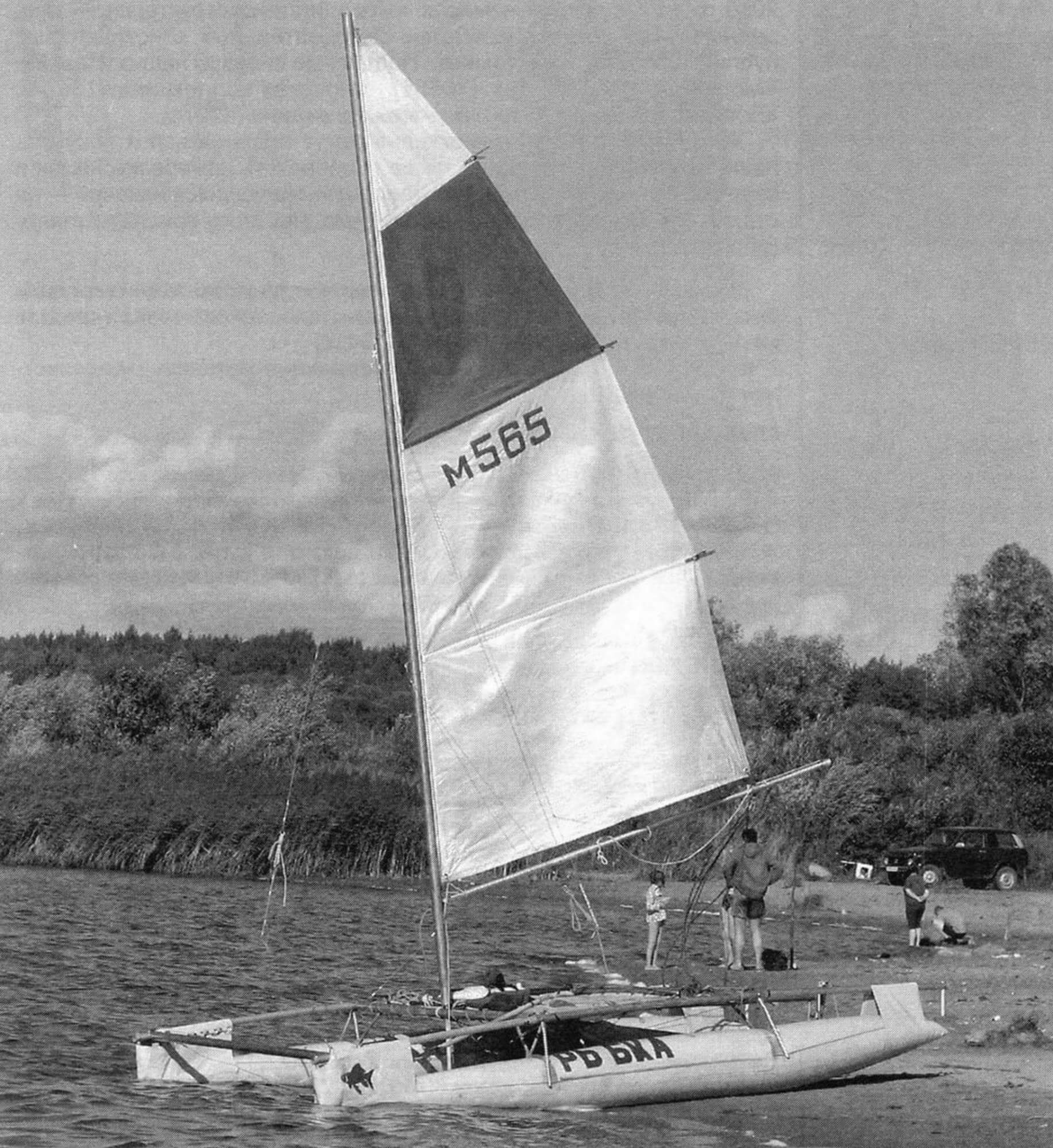
In my amateur boatbuilding practice, it turned out that the small two-seater leisure catamaran “Ryba” is far from the first; I built it even later than the large four-seater tourist sea-faring one (also sail-powered).
In some aspects, the small boat replicates the large one—for example, the two-hull (or more precisely, two-float) single-masted scheme, the set of power elements, and the materials used. However, many similar (single-purpose) nodes and even details are made differently, excluding, of course, standardized off-the-shelf products.
The “Ryba” catamaran is not only small in size but also simple in design, making it suitable for a novice shipbuilder.
However, even with its relatively small size, it is not possible to store it in an assembled state during the off-navigation period, let alone transport it to the “open water” on the trailer of a passenger car, or even in a passenger train carriage! Therefore, I made this catamaran collapsible.
The sail equipment of the vessel is also uncomplicated, and its control is accessible even to those who are just learning to sail.
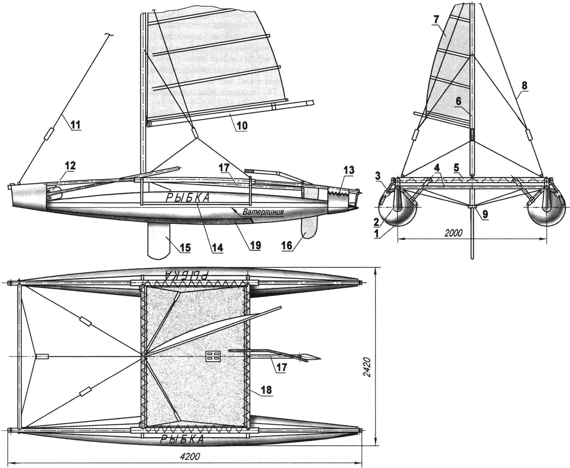
1 — float (2 pcs.); 2 — forepeak sides; 3 — shroud (4 pcs.); 4 — front cross-beam; 5 — middle sub-deck beam; 6 — mast; 7 — mainsail; 8 — standing rigging (shrouds); 9 — bowsprit; 10 — boom; 11 — forestay; 12 — paddle; 13 — rear pocket of the float; 14 — middle pocket-culisse of the float; 15 — centerboard; 16 — rudder; 17 — central longitudinal beam-carlings; 18 — rear sub-deck beam; 19 — additional hull bottom lining
Starting the description of the catamaran, I want to apologize in advance to professional sailors and shipbuilders—the names of some structural elements are not entirely correct (or do not quite correspond to the classical execution). But with beams and supports, from which, in fact, almost the entire power set of the vessel consists, I can “confuse” not only novice amateur shipbuilders but also professionals.
The buoyancy of the catamaran is provided by two inflatable single-chamber float-balloons, reminiscent in shape of corn cobs. The midship section of the float is located approximately 2/3 of its length from the bow.
The length of the floats is about 4 m, and the maximum diameter (at the midsection) is 420 mm. These float dimensions were chosen based on the required displacement, assuming that the waterline would follow the middle longitudinal line of the floats.
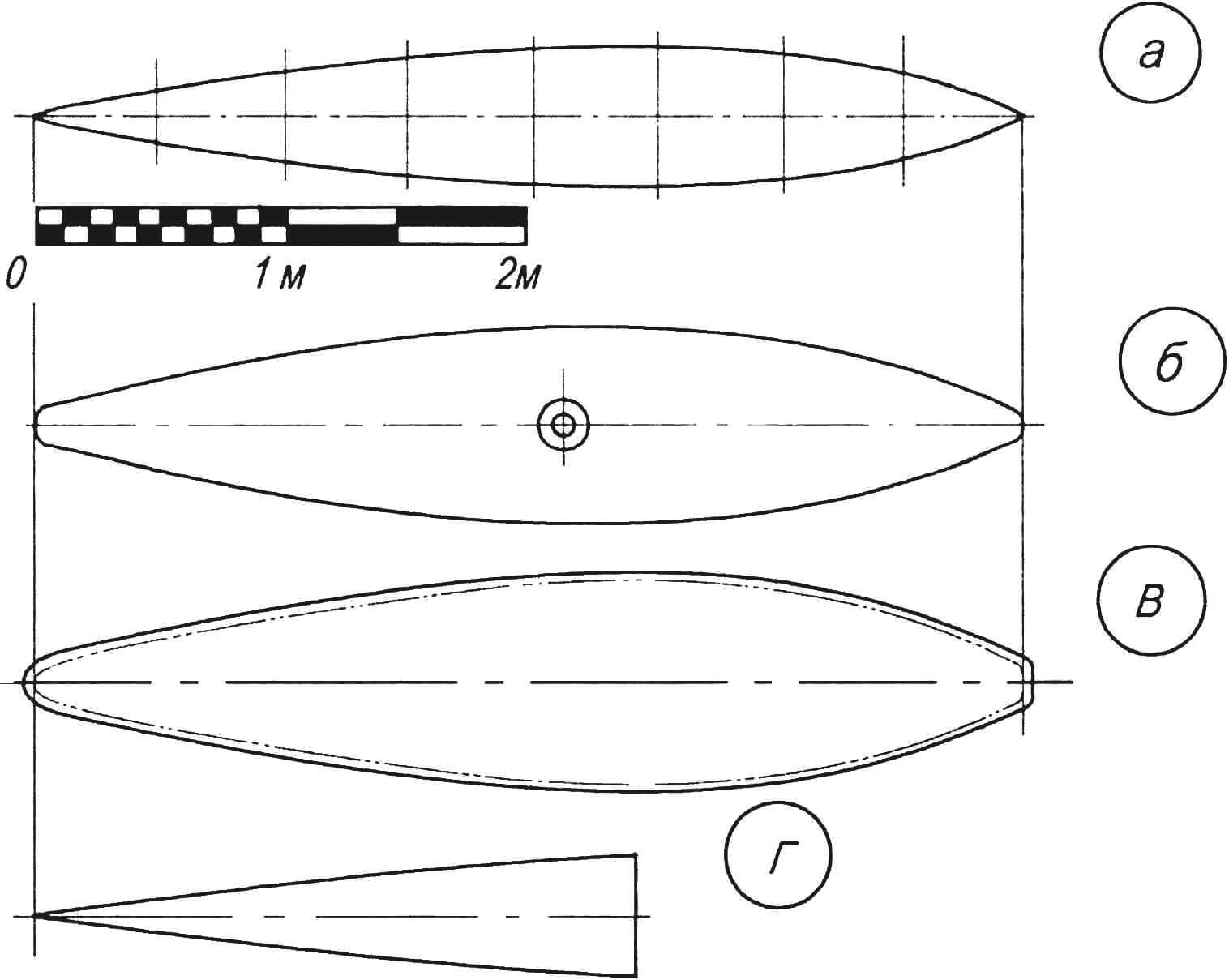
a — theoretical drawing; b — upper shell fabric; c — lower shell fabric (bottom part); d — fabric for additional lining of the bottom part
The material for the floats is technical synthetic fabric “Ferrari” with a double-sided film coating, but other waterproof and airtight materials can also be suitable. For example, my friend Andrey Chernikov, when building a similar catamaran, made the floats from the material used in advertising banners.
Before making the floats, a theoretical drawing with cross-sections at equal intervals was created. Each float was assembled from two parts (you can say halves, excluding the allowances for gluing on the template of one of them).
The layout of the parts’ templates was done on a flat surface. An axial line (or symmetry line) was applied to the fabric, and segments equal to a quarter of the length of the circumference of the corresponding section of the float were marked on both sides of it on the fabric. The ends of the segments were connected by a smooth curved line.
First, one part was cut out, placed on the fabric, and then the other part was cut out, but with allowances of 20-25 mm around the entire perimeter. To prevent the material from sliding, the fabric was glued to the floor, and the template was attached to the fabric with double-sided tape. Using these two templates, identical blanks for the second float were cut out.
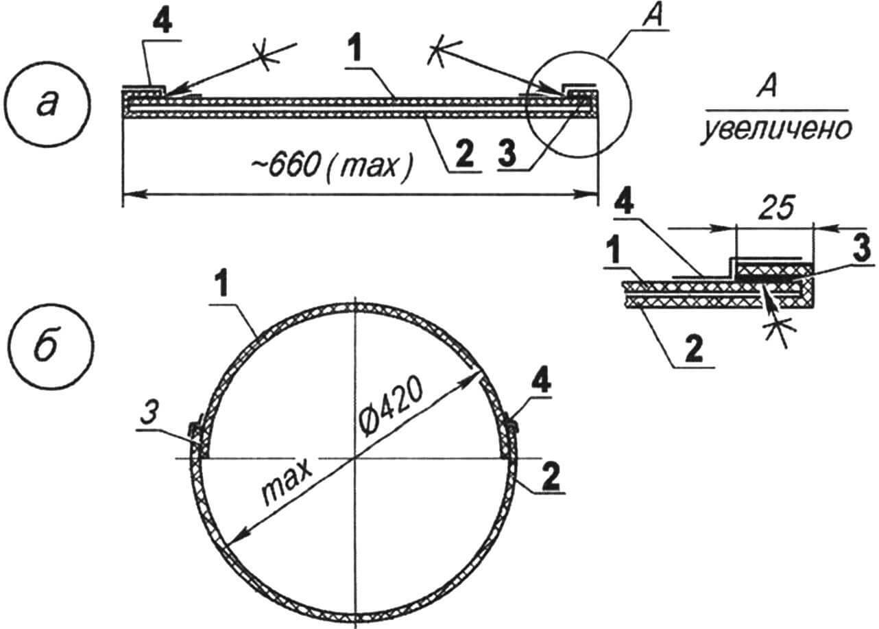
a — in the deflated state; b — in the inflated state; 1 — upper part of the shell; 2 — lower part of the shell; 3 — “Urmono” adhesive layer; 4 — sticky polyethylene tape
Before gluing the parts, the allowances on the second blank and the corresponding strips near the edges of the first were carefully prepared from both sides: slightly sanded with fine-grained sandpaper and wiped with acetone.
The halves were glued into a float by a simple butt joint of the blanks, with the allowances of the second overlapping the first, using “Urmono” glue following this technology. After applying the glue to the joined surfaces, the glue was allowed to dry for 20 minutes at room temperature. After bonding, the edges were heated with a heat gun and rolled with a roller.
The stern part was sealed last. Before that, the lower part of the air valve was inserted into the float. Later, in the upper part of the float, in the midship area, an additional circle of the same material was glued, and a hole was cut in it, where the valve was mounted (its upper and lower parts were connected here). For additional sealing (ensuring airtightness), a sticky polyethylene film was glued around the perimeter of the seams.
Finally, the float was inflated, and the seams were soaped and checked for airtightness. In the inflated state, pockets-slides for passing ropes and pockets-bags for threading the ends of stringers were glued to the float. However, these operations were performed after making the structural frame and fitting the location of its elements on the floats. Also, a triangular long, but not wide, strip of the same “Ferrari” material was glued to the bottom, approximately up to the midship area, serving as additional lining for the bottom.
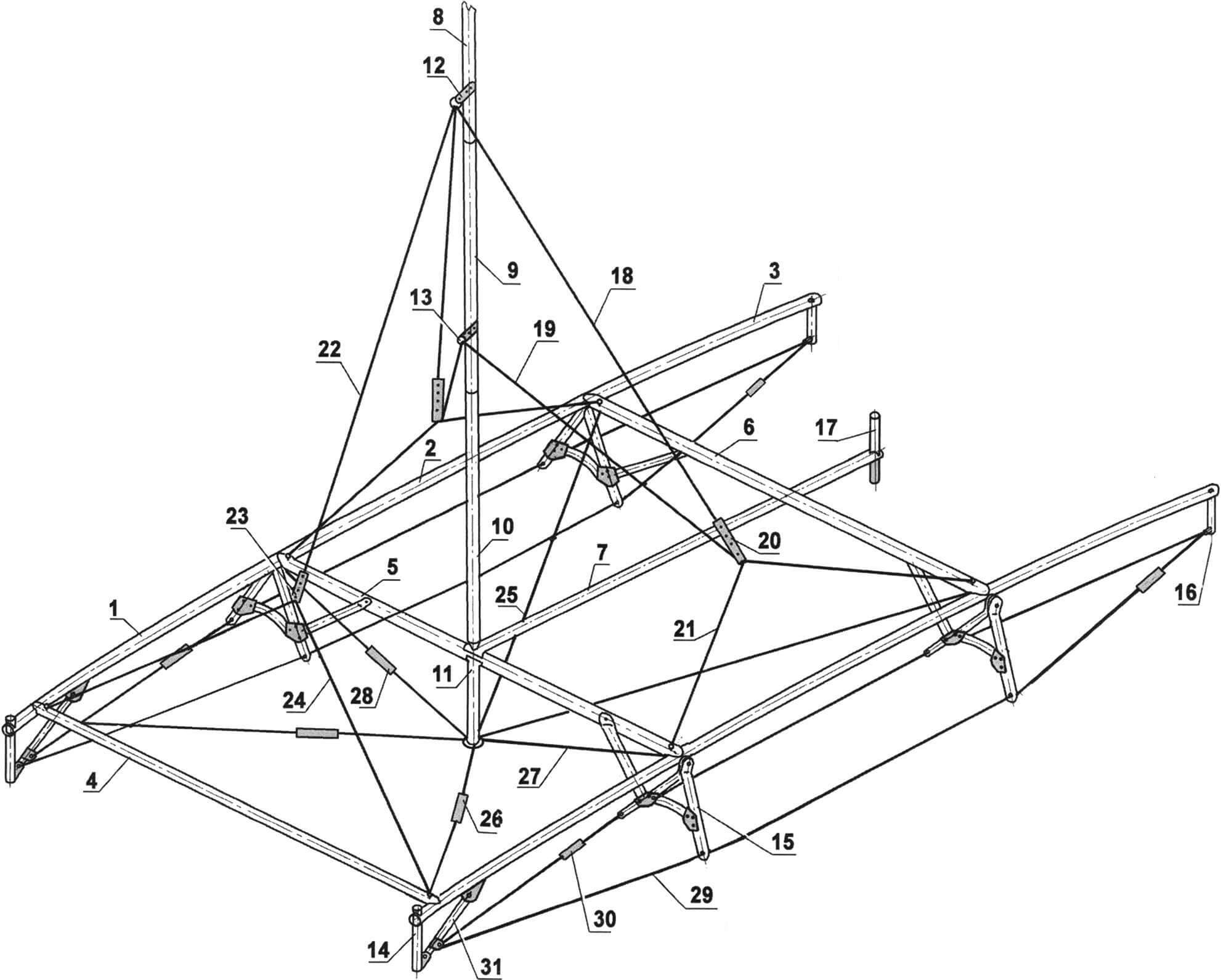
1 — bow part of the stringer (tube Ø45×1.5, 2 pcs.); 2 — middle part of the stringer (tube Ø48×1.5, 2 pcs.); 3 — stern part of the stringer (tube Ø45×1.5, 2 pcs.); 4 — bow beam (tube Ø48×1.5); 5 — middle mast beam-bim (tube Ø48×1.5); 6 — stern mast beam-bim (tube Ø48×1.5); 7 — central longitudinal (rudder) beam-carlings (tube Ø48×1.5); 8 — upper mast bend (tube Ø50×2); 9 — middle mast bend (tube Ø50×2); 10 — lower mast bend (tube Ø50×2); 11 — bowsprit; 12 — upper bracket (stainless steel, sheet s2, 2 pcs.); 13 — lower bracket (stainless steel, sheet s2, 2 pcs.); 14 — bow stand-forestay (tube Ø22×1.5, 2 pcs.); 15 — shroud with brace (tube Ø22×1.5, 4 pcs.); 16 — stern stand-backstay (tube Ø22×1.5, 2 pcs.); 17 — rudder axis bushing (tube Ø22×1.5); 18 — upper stay (rope Ø4, 2 pcs.); 19 — lower stay (rope, Ø4, 2 pcs.); 20 — shackle stay (4 pcs.); 21 — stay cleat (rope Ø4, 4 pcs.); 22 — forestay (rope Ø4); 23 — forestay shackle; 24 — stay cleat (rope Ø4, 2 pcs.); 25 — diagonal strut (rope Ø4, 2 pcs.); 26 — diagonal strut shackle (2 pcs.); 27 — transverse strut (rope Ø4); 28 — transverse strut shackle; 29 — stringer brace (rope Ø4, 4 pcs.); 30 — stringer brace shackle (4 pcs.); 31 — brace lever
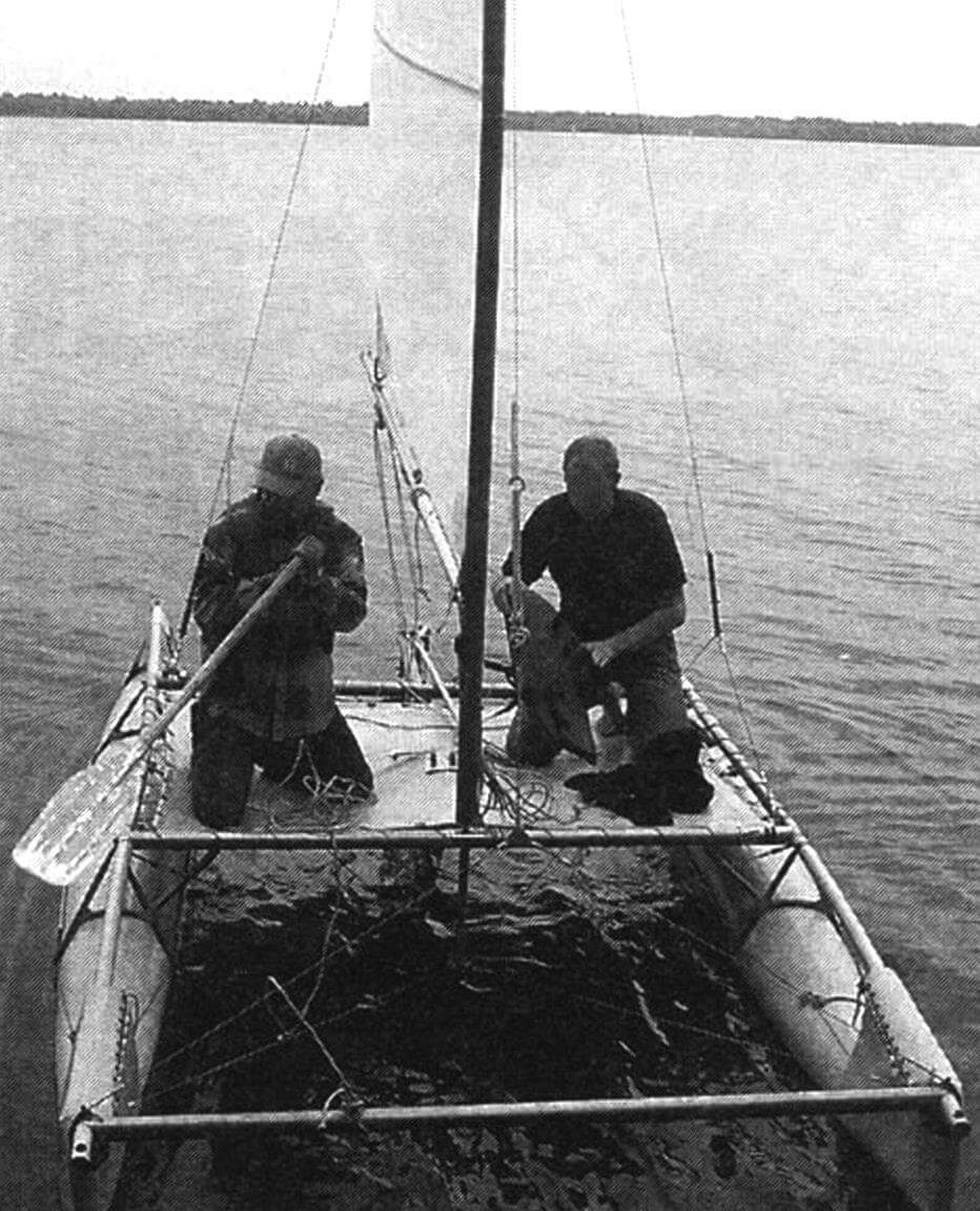
The structural assembly of the catamaran consists of a truss-like (more precisely, truss) framework, assembled from rigid longitudinal and transverse beams, additionally connected by cable ties.
Elements of the structural assembly longer than 2200 mm (such as stringers and the mast) are made in sections, composed of approximately equal lengths. This is done to facilitate the transportation of the catamaran in a disassembled state in public transport, subway, or train cars.
The mast is also considered part of the structural assembly because, together with its fastening elements—stainless steel cable stays and forestay—it redistributes loads between longitudinal and transverse elements.
The longitudinal elements of the structural assembly are stringers, each exceeding 4 m in length. Therefore, they are made composite. The central parts are made from a tube with a diameter of 48 mm and a wall thickness of 1.5 mm, while the end parts are made from a tube with a diameter of 45 mm. During assembly, the end parts of the stringers are inserted into the central parts by approximately 200 mm.
Low “hanging” (downward-facing) posts are cut into the ends of each stringer: a forestay at the front and a backstay at the rear. The lower ends of the posts are tightened with small cables, which slightly curve the stringers. Tensioning is done by a brace lever, the lower end of which is hinge-connected to the forestay post, and the upper end (after tightening the cables) is secured in a bracket on the stringer. Additionally, the cables are tensioned by turnbuckles. Thus, when a load is applied from above, the stringers work not in bending but in compression, transferring part of the load to the cables (during assembly, the cables are threaded through the floats’ slides).
At the center of each joint with the stringers, one end of the transverse underdeck beam—bim—is attached. There are two beams, and they are made from the same tube as the central part of the stringer. At this point, all three elements are fastened with a single common bolt. However, there is another bolt in the attachment node, but it serves as a pin for the first one. It has a ring-shaped head (like a rim bolt)—a carabiner attaches to it for the stays or forestay tangs. A loop of a spider rope is threaded onto the bolt under the nut and washer from below.
Two additional beams are present in the structural assembly: one transverse (front) and the other longitudinal (carlings). They are made from the same tube as the end parts of the stringers—diameter 45×1.5 mm. The front beam is attached to the stringers in the same way as the bims. The longitudinal beam is attached to the bims: to the front mast bim with a special bracket-bush and to the rear one with a regular bolt from below. An arm (T-shaped and vertical) is attached to the rear end of this carling beam—a section of a tube with a diameter of 22 mm. It serves as the bushing for the rudder axis. However, this element is no longer part of the structural frame.
The entire truss structure of stringers, bims, and beams is supported by shrouds, made in the form of brackets from a tube with a diameter of 22×1.5 mm. The legs of the brackets are pulled together by arcs, forming a saddle with the ends of the legs, which then rest on the floats. Ropes threaded into special grooves at the ends of the legs are used to tighten the ends of the stringers.
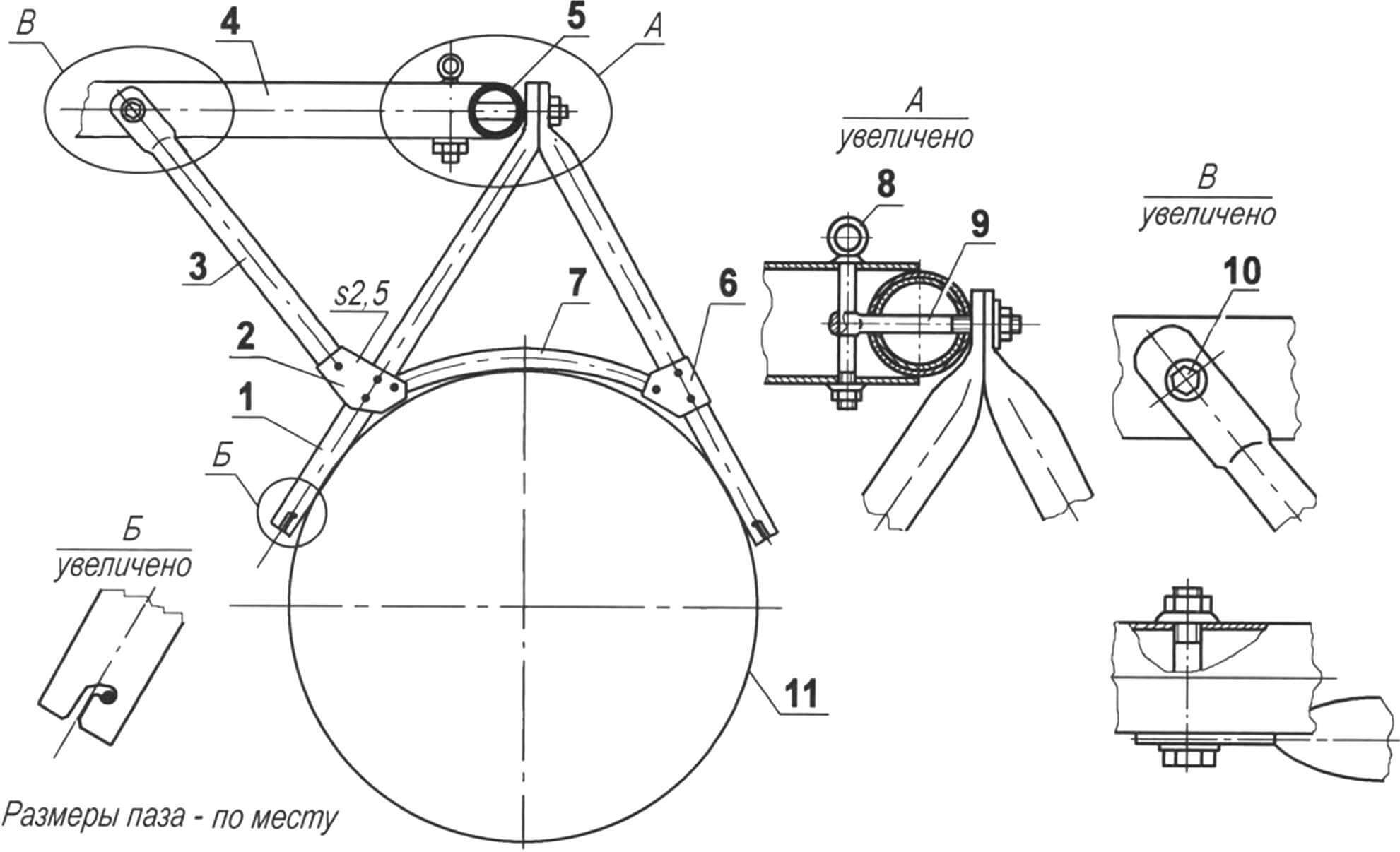
1 — leg (2 pcs.); 2 — brace pad (duralumin, sheet s2, 2 pcs.); 3 — brace; 4 — transverse beam-bim; 5 — stringer; 6 — brace-support pad (duralumin, sheet s2, 2 pcs.); 7 — brace-support; 8 — outer rim bolt M12 with two shaped washers; 9 — inner rim bolt M12; 10 — brace fastening (bolt M10 with shaped and flat washers); 11 — float
To fix the mutual position of the shrouds and the frame from the bottom, stops are installed and secured at a 45° angle to the transverse beams on the inside leg of each shroud. These stops prevent the shroud-brackets, together with the floats, from tilting.
The attachment of the floats to the structural assembly (or the floats to it) is carried out in two ways. Both attachments are relatively free since the frame is a rigid element, while the floats are flexible and can slightly change their shape.
The first connection of the floats to the structural assembly is through tensioning ropes of the stringers, which are inserted into slides glued to the floats on the sides in their central part. The second connection is through pockets, also glued to the floats at the bow and stern, and worn on the ends of the stringers.
The catamaran mast is made from the same tube as the bims and the central part of the stringers—diameter 50×1.5 mm. The total length of the mast is 6 m, so it is made composite from three tube sections, each 2 m long. The sections are joined at the knee joints using internal bushings secured in one of the knees (lower) with one of the screws attaching the mast’s cheek to the knee. The next (higher) knee is placed onto the bushing and is only fixed on it to prevent rotation by a locking screw screwed into the wall of the bushing. A corresponding groove is cut into the mast knee under the screw. The mast is supported on a step, secured in the middle of the front bim. The step, in turn, is supported together with the front mast bim by a shroud-strut, secured with a spider and cable stays: two diagonal ones—on longitudinal and transverse structural elements (stringers and bims) at their joints and another transverse one—on the middle of the stringers. The height of the shroud-strut is such that it is slightly (by 50–60 mm) above the calm water surface.
1 — upper knee; 2 — cheek (special duralumin profile); 3 — connecting bushing (duralumin D16T, tube Ø48×1.5); 4 — lower knee; 5 — securing cheek to knee (screw M5 with countersunk head, as needed); 6 — securing cheek, knee, and bushing (screw M5 with countersunk head); 7 — lock (screw M6)
The mast itself is fastened to the structural elements at the front with a forestay and on the sides with double shrouds. The upper end of the forestay is attached to the mast at approximately 2/3 of its height through an eye. Its lower end is split into whiskers. Each whisker goes to the attachment point of the front beam to the stringer and hooks there with a carabiner onto the eye of the bolt.
1 — mast (duralumin, tube Ø50×2); 2 — mast spur (duralumin); 3 — step (special bolt M10, stainless steel); 4 — washer (heel) (duralumin); 5 — undermast beam—middle underdeck beam-bim (duralumin, tube Ø80×2); 6 — bracket-bush (stainless steel, sheet s1); 7 — spout (stainless steel, sheet s1); 8 — strut of the mast strut (duralumin tube Ø28×2); 9 — fastening bushing (duralumin); 10 — strut fastening (nut M10, stainless steel); 11 — mast strut (duralumin); 12 — cable (stainless steel)
Both shrouds are split at the top and bottom. The upper ends of the whiskers are attached to the mast, one in the middle and the other at 2/3 of its height. The lower ends of the whiskers are secured to the sides at the points where the bims are attached to the stringers.
The rudder blade and the centerboard are similar in design. However, I made them from different materials, although they can be made from the same. I covered the rudder blade with fiberglass, and the centerboard is sheathed with a 1 mm thick duralumin sheet. The structural assembly for both elements is the same—one curved longitudinal spar with a brace at the break point. In this case, the centerboard covering is glued to the spar (and its rear edges are bonded), while the rudder blade covering is epoxy-bonded.
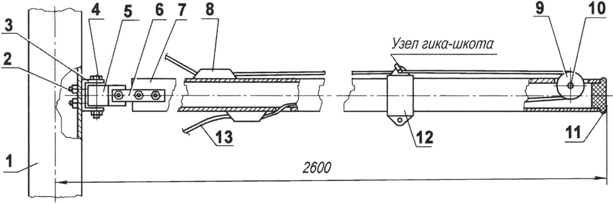
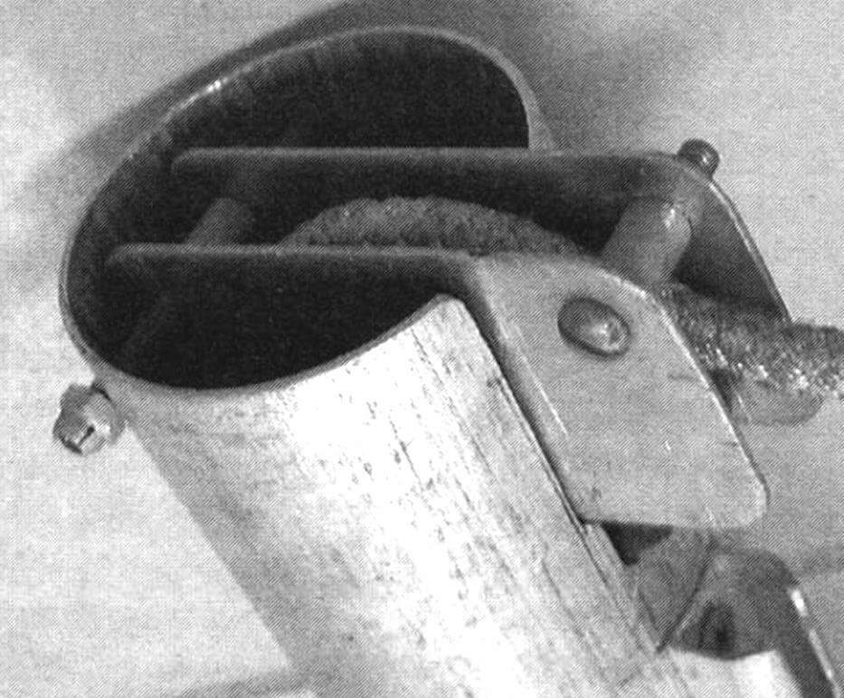
1 — mast; 2 — bracket attachment (screw M5, 2 pcs.); 3 — bracket (bent channel, stainless steel, sheet s2); 4 — gudgeon pin (screw M8); 5 — gudgeon (duralumin D16T); 6 — cheek pieces (stainless steel, sheet s2, 2 pcs.); 7 — boom (D16T, tube Ø30×1.5); 8 — stopper (plastic, purchased item, 2 pcs.); 9 — roller (plastic, purchased item); 10 — roller pin (stainless steel, circle 5); 11 — cap (nylon); 12 — clamp; 13 — boom vang (synthetic rope Ø8)
The centerboard is suspended on a longitudinal steering beam in a bracket-eyelet and is secured by two pairs of ropes threaded to the spars. The centerboard is operated by two travelers—one serves to hold the blade in the working position, and the other—in the raised position. The free ends of the travelers are fixed in stoppers located on the deck.
In the event of an unexpected collision with the bottom or an underwater obstacle, the centerboard has the ability to deflect backward and rise, and after passing the obstacle, it returns to the working position.
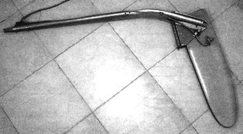
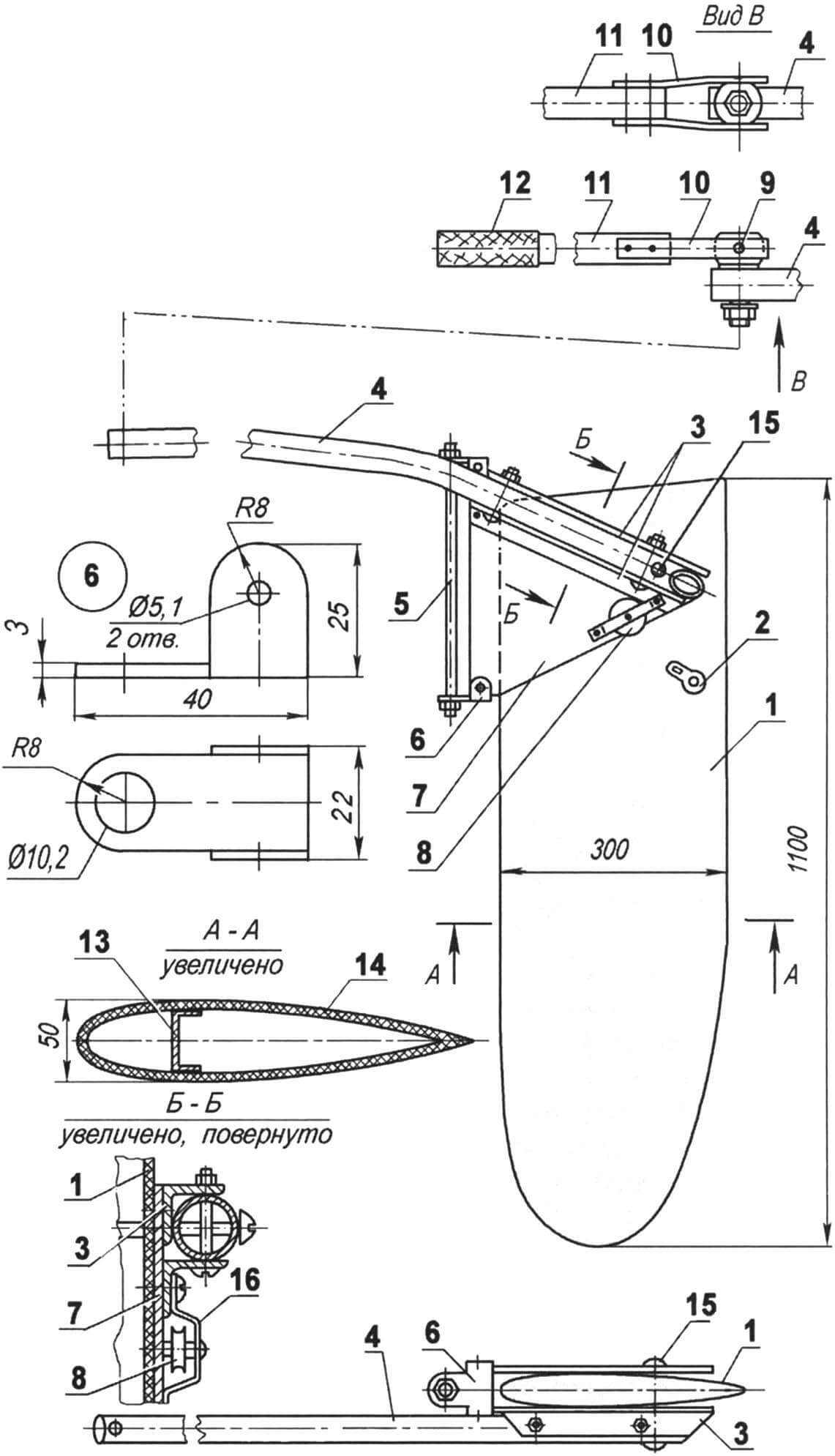
1 — rudder blade; 2 — traveler eyelet; 3 — brackets for attaching the tiller to the pad (duralumin angle 25×25, 2 pcs.); 4 — tiller (duralumin tube Ø30×1.5); 5 — rudder shaft (stud M10); 6 — bracket connecting the rudder shaft and cheek pieces; 7 — cheek piece (duralumin, sheet s3, 2 pcs.); 8 — traveler roller; 9 — hinge pin; 10 — pad (stainless steel, sheet s2, 2 pcs.); 11 — extender (tube Ø30×1.5); 12 — handle (rubber); 13 — rudder spar; 14 — rudder covering; 15 — rudder shaft; 16 — bracket-clamp for roller
The rudder blade is fastened to the axis between two cheek pieces, and a tiller is attached to one of the cheek pieces. The tiller allows the rudder blade, mounted on the axis in a bushing at the end of the steering beam, to rotate. For ease of control, the tiller is equipped with an extension, connecting them with a universal joint. The lifting and lowering of the rudder blade is carried out by the traveler attached to it, the end of which is also fixed in a stopper on the deck.
Currently, the “Rybka” catamaran is equipped with a purchased Bermuda-type sail. However, initially, it had a homemade sail that was also quite suitable. Later, it was given to Andrey Chernikov, who built a similar catamaran. With this sail, his vessel still demonstrates quite high sailing qualities.
The self-made sail is a classic Bermuda-type sail in terms of construction. The only modification is the addition of a patch pocket for the batten along its lower luff. As sailing trials and operation have shown, this modification proved to be beneficial.
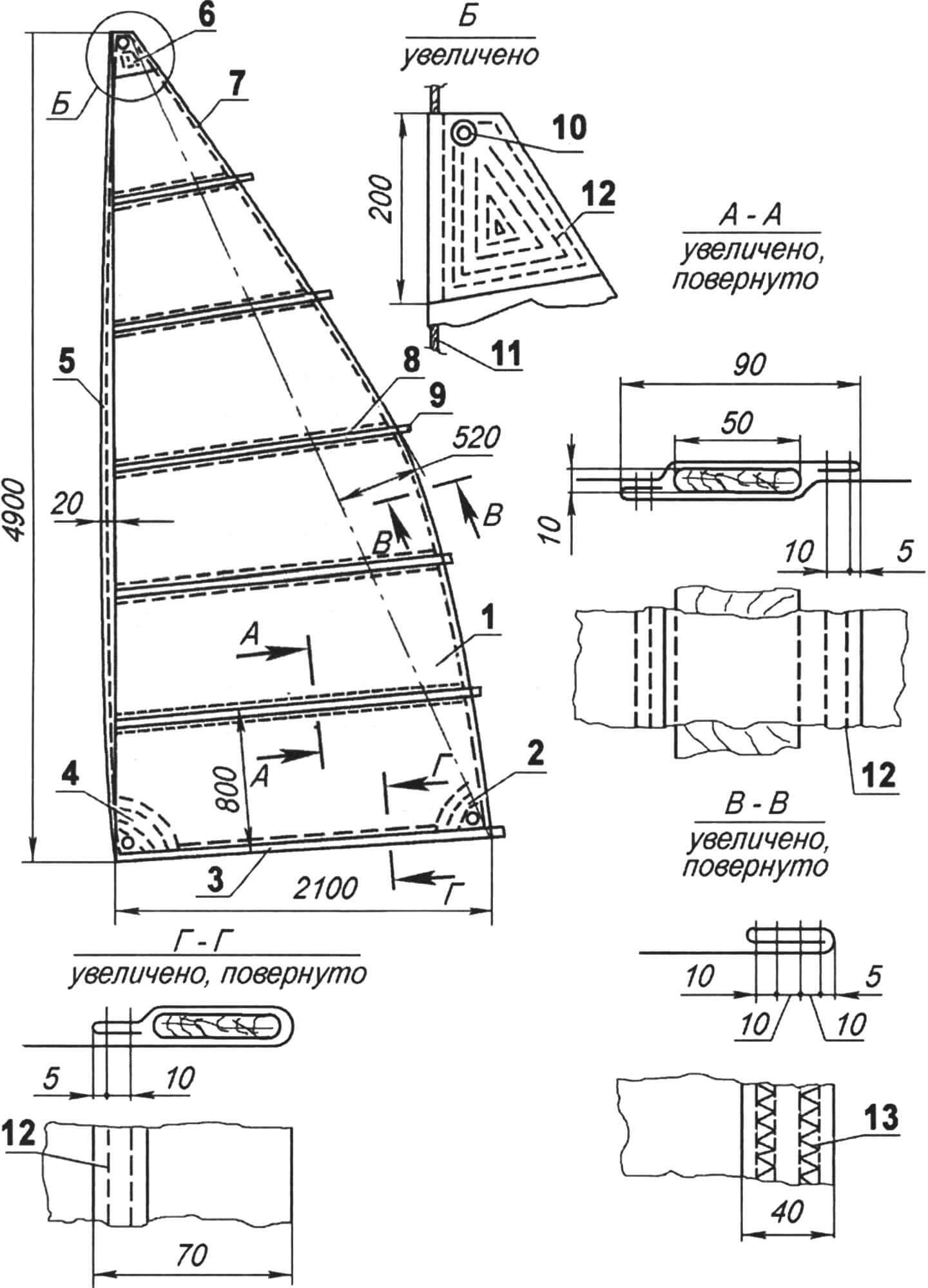
1 — sail fabric (“Yakhta” fabric); 2 — reinforcing diagonal; 3 — lower luff patch pocket; 4 — reinforcing diagonal; 5 — front luff; 6 — reinforcing diagonal of the halyard corner; 7 — rear luff; 8 — batten pocket (5 pcs.); 9 — batten (6 pcs.); 10 — eyelets (3 pcs.); 11 — luff rope; 12 — straight stitch; 13 — zigzag stitch
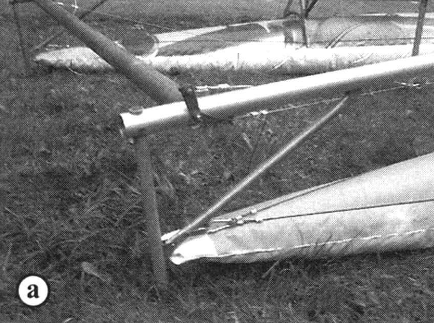
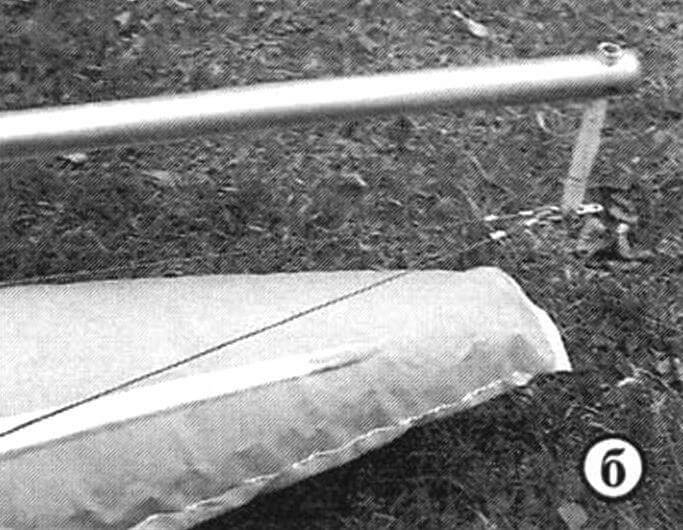
The oar, although not the main propeller for the catamaran, is essential, especially during maneuvers in confined spaces, not to mention sailing upwind, as well as when mooring or departing from the shore (if you want to avoid getting wet), and sometimes just to stretch your muscles. I have two identical folding oars. The shaft of the oar is made of a 30 mm diameter aluminum tube, and the blade is made of a 1.5 mm thick aluminum sheet. When not in use, the oars are stowed along the sides without causing any obstruction: the blades are tucked into the front pockets, and the shafts are placed along the stringers, with the handles resting on the undermast beam.
The weight of the catamaran is approximately 100 kg, and the entire structure is packed in two cases, with the mass distributed roughly equally. However, it would be better to divide it into three packages—this way, handling the luggage will be easier, especially when lifting it to the upper shelf in a passenger train carriage.
K. TAGILTSEV
Recommend to read
 TWO “VYATKA” — AND THE CAR!
The readers of "M-K" has long been known to experienced lab simulation and design club of young technicians of the Siberian branch of the USSR Academy of Sciences. A development of this... SUN TERRACE
The idea to build the terrace was inspired by the vacant greenhouse dimensions 3x4 m of the old wooden window frames, which stood idle for the second summer season. No need for her...
