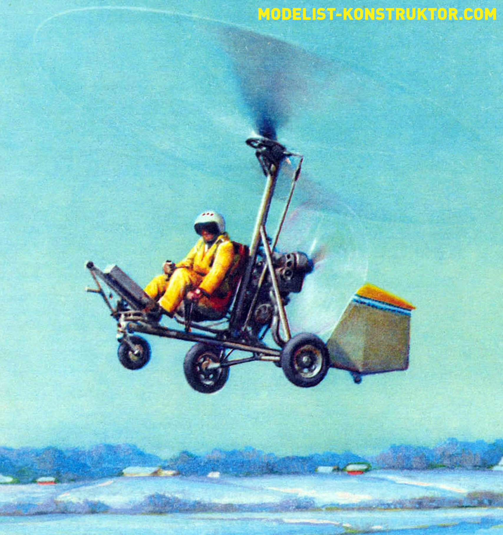
The history of creating our autogyro, later named DAS-2M, spans over two decades. The first flight of the DAS autogyro took place in May 1980 in an unpowered version, towed by a “Zhiguli” car. It happened at one of the agricultural aviation airfields near Tula. After the first flight, we realized that the aircraft was successful. However, it took another nine years, during which we worked on the engine, before in the summer of 1989, at the “Riga Aviation Salon,” the most experienced test pilot of the LII V. M. Semyonov after just one run lifted the DAS-2M into the air. This event was later marked at the Light Aviation Competitions with a special prize from the Mil Design Bureau, as reported to the readers of the magazine “Modelist-Constructor” No. 6 for 1990. According to the test pilot, the aircraft has good flight characteristics and effective control.
As experience has shown, an autogyro is primarily a good power unit. It’s no coincidence that the last nine years were devoted to it. During this time, a two-cylinder opposed engine was developed, allowing to achieve a static thrust of 145 kgf, which made it possible for the autogyro to successfully take off.
CONSTRUCTION OF THE DAS-2M AUTOGYRO
Fuselage – truss, tubular, detachable structure. The main element of the fuselage is a frame consisting of horizontal and vertical (pylon) pipes Ø 75X1, made of steel 30XGSA. Towing device with lock and air pressure receiver, instrument panel, pilot’s seat equipped with a safety belt, control device, three-wheel, with a nose steerable wheel chassis, power unit with a pushing propeller installed on the engine frame, stabilizer, directional fin with rudder, ball joint of the main rotor. An auxiliary tail wheel with a diameter of 75 mm is installed under the fin. The pylon together with struts Ø 38X2 1260 mm long, tubular beams of the main wheels Ø 42X2 770 mm long, made of titanium alloy VT-2, and struts Ø 25X1 730 mm long made of steel 30XGSA forms a spatial power frame, in the center of which the pilot is located. The pylon is connected to the horizontal fuselage tube and the ball joint of the main rotor with titanium struts. Spark plugs made of duralumin V95T1 are installed in the pipes at the location of the struts.
Power Unit – with a Pushing Propeller. It consists of a two-cylinder opposed two-stroke engine with a working volume of 700 cm3 with a reducer, a pushing propeller, and an electric starter, a friction clutch of the pre-spinning system of the main rotor, an 8-liter fuel tank, and an electronic ignition system. The power unit is located behind the pylon, on the engine frame.
Engine is equipped with a duplicated electronic contactless ignition system and a tuned exhaust system.
Pushing Wooden Propeller is set in motion by a V-belt reducer consisting of driving and driven pulleys and 6 belts. Dampers are installed on the reducer to reduce torque unevenness.
Main Rotor with a diameter of 6.60 m is two-bladed. The blades, consisting of a fiberglass spar, foam filling, and covered with fiberglass, are installed on a hub with a single horizontal hinge mounted on the pylon. Uncontrolled trim tabs for adjusting the coning of the main rotor are located at the blade tips. The hub of the rotor is made of duralumin of grade V95T1. The axis of the main rotor with a diameter of 25 mm made of steel 30HN2MVFA, connected to the horizontal hinge, rotates in roller conical bearings. On the axis of the main rotor, there are a driven gear of the pre-spin reducer and a main rotor tachometer sensor. The axes of the main rotor are placed on a ball joint, which is connected to the upper control fork. The latter is equipped with a panel with a driving gear of the pre-spin reducer, mounted on a freewheeling clutch, and a device for forcibly disengaging the gears of the pre-spin reducer of the main rotor. The reducer is driven by universal joint shafts, an angle gearbox installed on the pylon, and a friction clutch located on the engine. The friction clutch consists of a driven rubber roller mounted on the shaft of the universal joint shaft and a driving duralumin drum located on the engine shaft. The friction clutch is controlled by a lever mounted on the control handle.
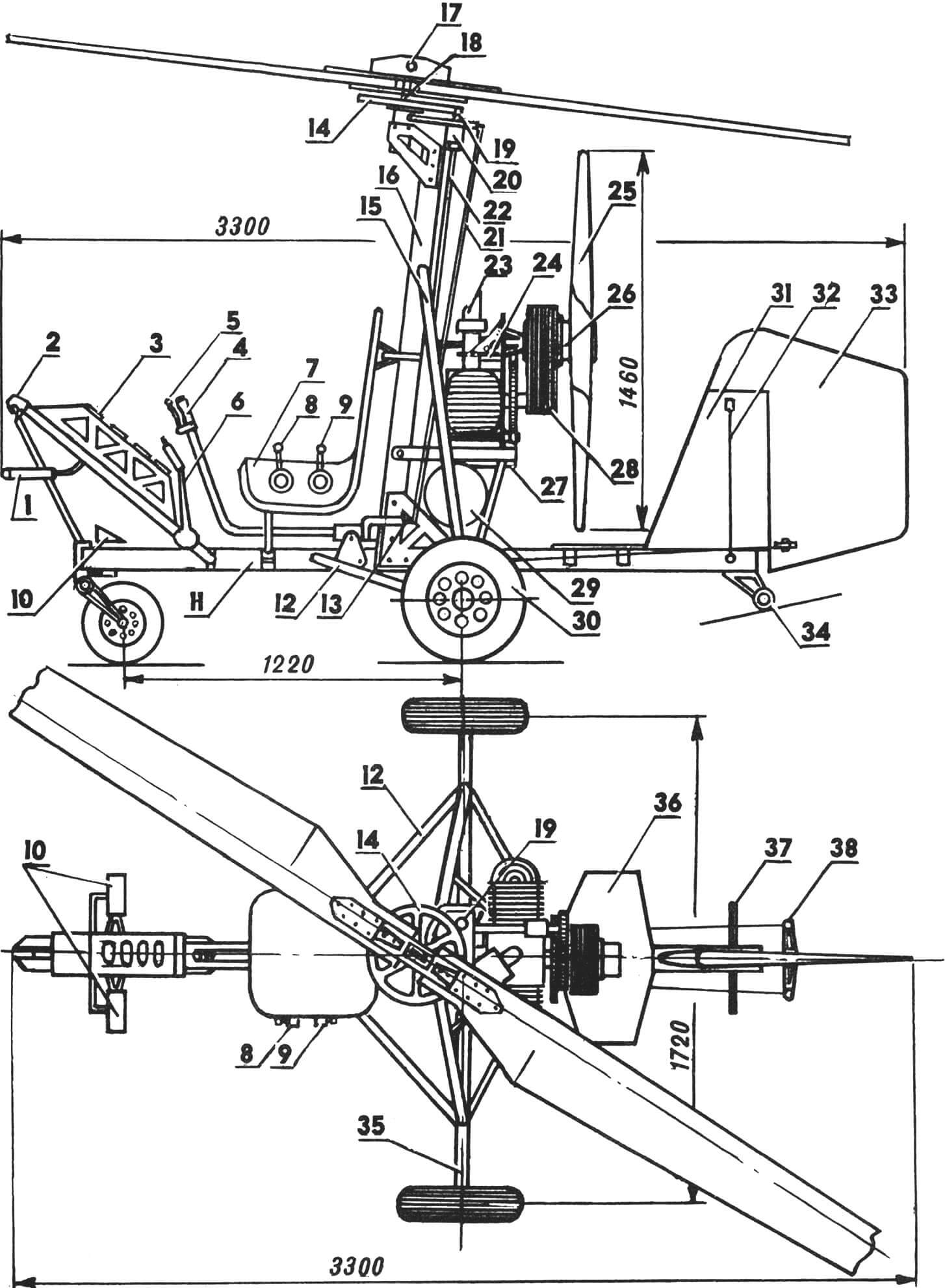
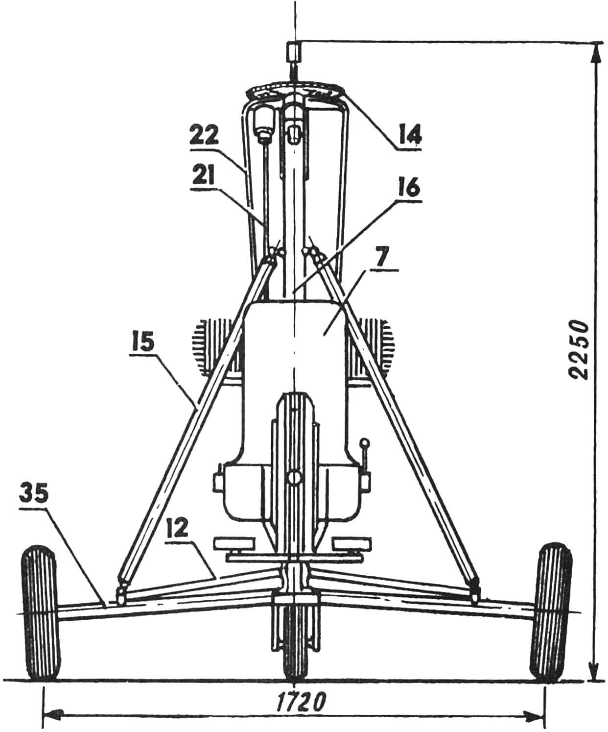
1 — air pressure receiver, 2 — towing lock, 3 — instrument panel, 4 — control handle, 5 — lever of the control clutch friction of the pre-spin system of the main rotor, 6 — parking brake lever, 7 — pilot’s seat, 8 — throttle control lever of the carburetor, 9 — lever of the device for forcibly disengaging the gears of the pre-spin reducer, 10 — control pedals, 11 — horizontal fuselage tube, 12 — strut, 13 — lower fork of the control system, 14 — driven gear of the pre-spin reducer, 15 — struts, 16 pylon, 17 — axis of the horizontal hinge, 18 — axis of the main rotor, 19 — driving gear of the pre-spin reducer, 20 — housing of the freewheel clutch and device for forcibly disengaging the gears of the pre-spin reducer, 21 — control system tie rod, 22 — universal joint shaft of the pre-spinning, 23 — carburetor, 24 — housing of the bearings of the friction clutch of the pre-spinning, 25 — pushing propeller, 26 — hub of the pushing propeller, 27 — electric starter, 28 — reducer of the pushing propeller, 29 — fuel tank, 30 — main chassis wheel, 31 — fin, 32 — fin spreader, 33 directional rudder, 34 — auxiliary tail wheel, 35 — tubular beam of the main chassis wheel, 36 — stabilizer-screen, 37 — console of the spreader, 38 — control wheel rocker.
The main rotor is not conventionally shown from the front view.
Changes in roll and pitch are controlled by a lever that affects the position of the lower control fork, connected by rods to the upper fork, which, in turn, leads to a change in the inclination of the plane of rotation of the main rotor. The forks are connected with rods using standard joints with self-aligning bearings. Directional control is carried out by the directional rudder, connected by a cable system to the pedals, which also control the nose wheel. To compensate for the hinge moment, the directional rudder is equipped with a horn-type compensator. The directional rudder and symmetrical-profile fin are assembled from 16 plywood ribs with a thickness of 3 mm, pine stringers of 5×5 mm, covered with percale, and coated with nitro lacquer. The fin is installed on the horizontal fuselage tube with anchor bolts and two cable spreaders. The relative thickness of the fin and directional rudder is 5%. The stabilizer with an area of 0.25 m2 is made of 3 mm plywood, covered with percale, and painted. The stabilizer also has a zero angle of incidence and serves as a screen for the pushing propeller.
Chassis of the autogyro is three-wheeled. The front steerable wheel with a size of Ø 300X80 is connected to the pedals through a gear reducer with a gear ratio of 1:0.6 and equipped with a parking brake of a drum type with a diameter of 115 mm. Main wheels – Ø 450X100. Chassis track – 1.72 m, wheelbase – 1.23 m. Tubular beams of the main wheels are installed on the horizontal fuselage tube using rubber silent blocks, and the chassis does not have shock absorbers. In the winter version, the wheels of the chassis are replaced with skates or skis with a size of 1.55X0.2 m. In the hydro variant, the chassis design allows for the installation of floats, the length of which is 3.5 m, width is 1.6 m, and displacement is 500 kg.
Instrument Panel is located on the towing device truss. The instrument panel includes an airspeed indicator, variometer, altimeter, connected to the air pressure receiver, tachometers for the main and pushing propellers. On the control handle, there are emergency engine shutdown switch and friction clutch control lever. Throttle control lever of the carburetor and the device for forcibly disengaging the gears of the pre-spin reducer system are located on the pilot’s seat on the left. On the right, there is the ignition switch. To the left of the instrument panel is the parking brake lever. The drive for all autogyro mechanisms is provided by cables with Bowden sheaths.
Technical Specifications of Autogyro DAS-2
Main Rotor
Main rotor diameter, m – 6.60
Swept area, m2 – 34.2
Blade taper – 1.6
Blade profile – ASA 23012
Blade filling coefficient – 0.046
Main rotor axis deflection:
backward 0…+200
lateral 0…+70
Horizontal Stabilizer
Stabilizer span, m – 0.65
Stabilizer area, m2 – 0.25
Horizontal stabilizer arm, m – 0.7
Stabilizer angle of incidence – 0°
Vertical Stabilizer
Vertical stabilizer area, m2 – 0.16
Vertical stabilizer arm, m – 1.2
Directional rudder area, m2 – 0.40
Rudder deflection angle +30°
Fuselage
Width, m – 0.5
Midsection area, m2 – 0.65
Chassis
Wheelbase, m – 1.23
Track, m – 1.72
Wheel sizes:
nose – Ø 300X80 mm
main – Ø 450X100 mm
Distance from the main rotor axis to the main wheels (backward), mm – 190
Weight Data
Maximum takeoff weight, kg – 280
Empty weight of autogyro – 180
Fuel weight – 7
Specific load – 8.2 kg/m2
Power Unit
Power, hp – 52
Maximum propeller RPM, rpm – 2500
Propeller diameter, m – 1.46
Propeller thrust at idle (at 2500 rpm), kgf – 130
Speed
Takeoff speed, km/h – 40
Landing speed, km/h – 0
Cruising speed, km/h – 80
Maximum speed, km/h – 100
Rate of climb, m/s – 2.0
V. DANILOV, M. ANISIMOV, V. SMERCHKO, Tula
Recommend to read
 NOT THE SPRING AND GRAVITY
Conclusion of any country fence is the gate. Often achilladelis provide simple devices that automatically close the gate after you pass through them — this steel springs, and rubber... “VIRTULA” FOR ALL
Designing a new racing control line aeromodel, we opted not on some extravagant options, but the proven classic design, well established and fully proven to date. The base design was...
