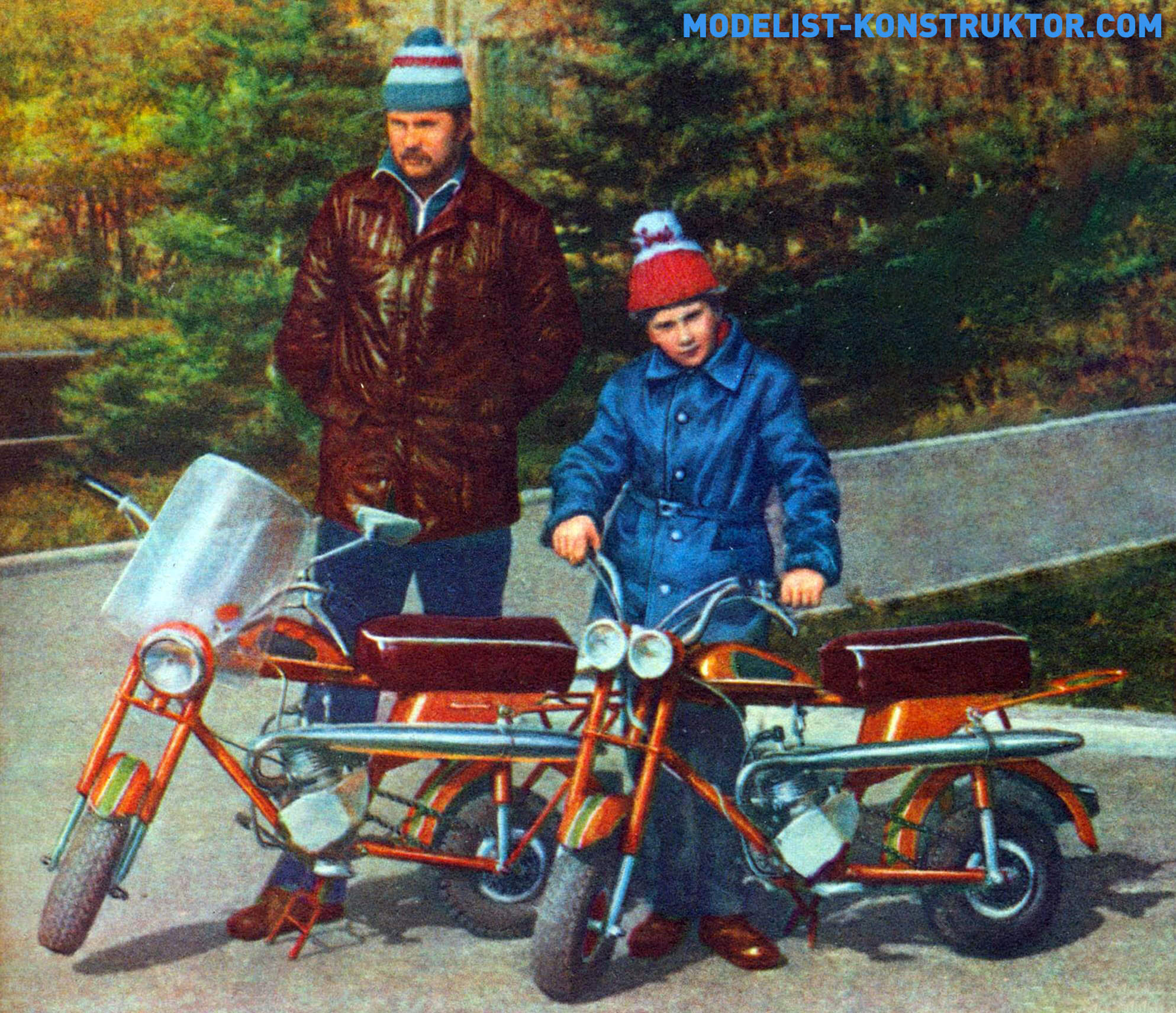
According to today’s classification, micro motorcycles designed for city use are called this way (their dimensions allow storing the vehicle in an apartment and transporting it in a passenger car).
And “family” because the design turned out to be suitable for both me and my son. We built two minibikes: they differ only in headlights but are otherwise identical. This article will focus on this typical “family” design.
The most complex component, naturally, is the frame. It is welded from steel pipes. The crossbar is solid, while the front and rear power braces are composite. Bent on a pipe-bending machine and trimmed blanks of the braces are welded so that the place of their connection resembles a handshake, figuratively speaking. This is done to shift the D-6 engine to the left because the driven sprocket is also shifted in the same direction due to the large width of the rear wheel (it, like the front one, is from a kart).
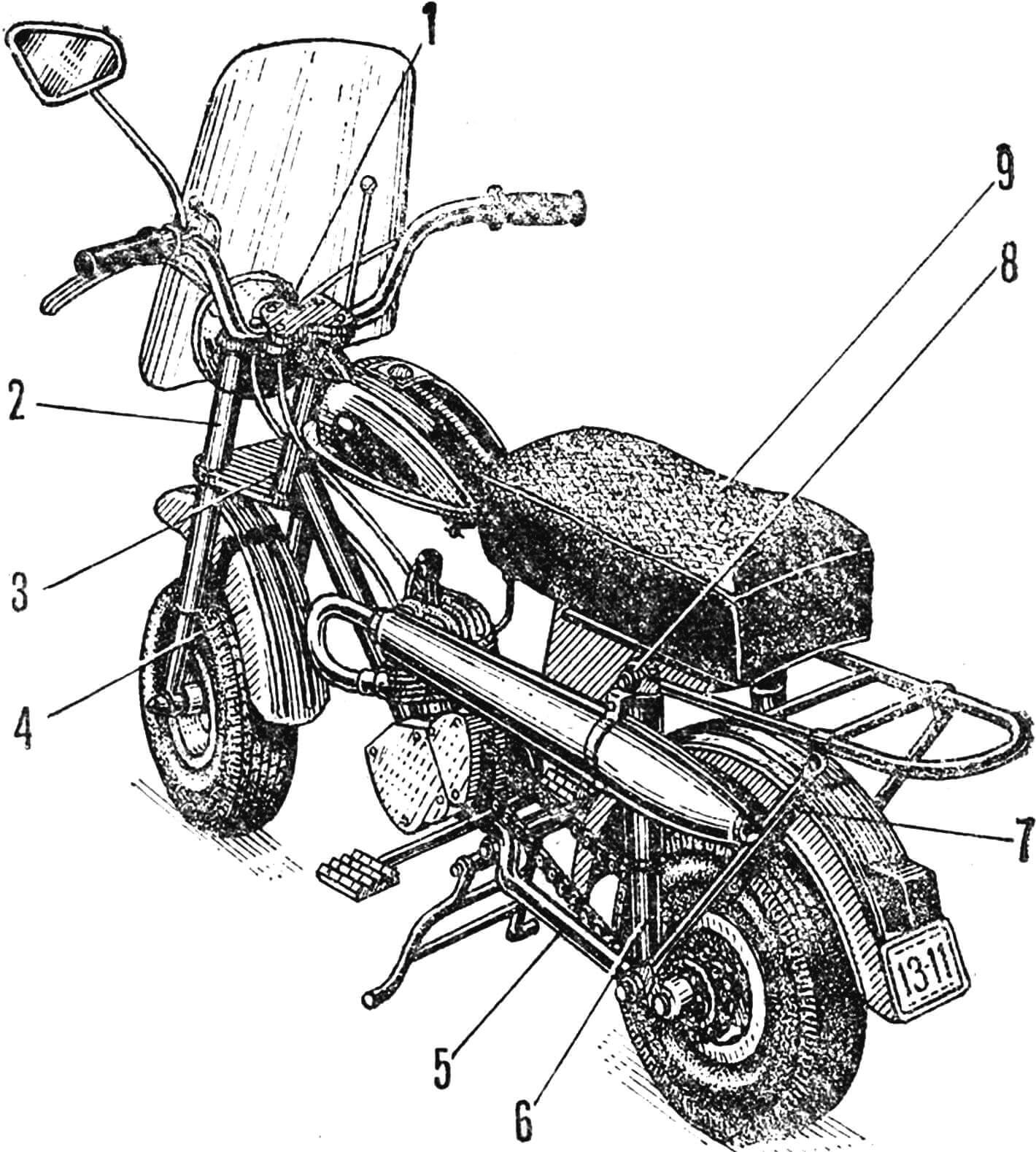
1 — handlebar caps, 2 — front fork, 3 — frame steering bushing, 4 — front fender, 5 — swingarm fork, 6 — shock absorber, 7 — brace of the external trunk, 8 — bushing for attaching the shock absorber and external trunk, 9 — folding seat.
The frame of the internal trunk is connected at one point with the crossbar and rear brace. Its main power element is bent like a horseshoe from a Ø20 mm pipe and welded with a segment of the same pipe, which has a cut for an ordinary hinge. The seat base is attached to the latter with screws. A 10mm plywood seat base is glued on top, covered with a foam cushion and upholstered in faux leather.
The seat also serves as a trunk lid, formed by walls of a 1mm thick sheet metal wrapped around the rear brace and welded to the frame. The bottom of the walls is closed with an inclined sheet metal bottom. The rear part of the trunk is reinforced from the inside with triangular patches attached to the frame on the left and right. The patches each have a horizontal Ø10 mm bushing for attaching shock absorbers and the external trunk.
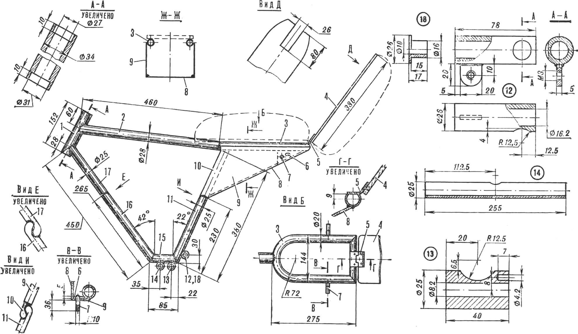
1 — steering bushing, 2 — crossbar, 3 — frame of the internal trunk, 4 — folding seat base, 5 — hinge, 6 — patch, 7 — bushing for attaching the shock absorber and external trunk, 8 — internal trunk bottom, 9 — wall, 10, 11 — details of the rear brace, 12 — fork bushing, 13 — brake lever bushing, 14 — footrest bushing, 15 — crossbar, 16, 17 — details of the front brace, 18 — bronze bearing (2 pcs.).
At the bottom, footrest, brake lever (to the crossbar), and swingarm (to the rear brace) bushings are welded to the frame. The first two, made of Ø25 mm pipes, are not particularly complex. However, the brake lever bushing has a blind hole drilled where the end of the brake spring is inserted (the other end is on the lever).
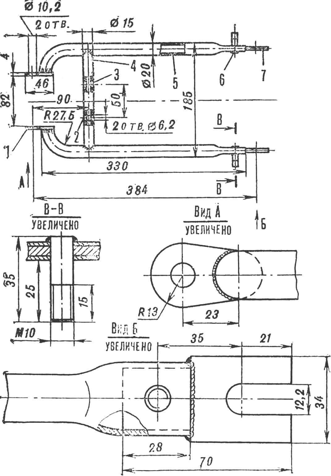
1 — hinge, 2, 3 — holes for attaching the fender, 4 — brace, 5 — side tube, 6 — bushing for attaching the shock absorber and brace of the external trunk, 7 — lug.
The swingarm bushing is more intricate. It is asymmetric relative to the brace, has a lug with a thread for the screw tensioning the brake cable, and two bronze sliding bearings for the swingarm fork axis. The bearings are installed after welding, and to ensure the coaxiality of their holes, they are processed with a reamer. The fork is symmetrical about the longitudinal axis. It consists of hinges, side tubes with a Ø20 mm, lugs, and a brace with a Ø15 mm. The front ends of the side tubes are bent, the rear ones are flattened, and all of them are welded to the hinges and lugs. Ø10 mm bushings for the stems of the shock absorbers and braces of the external trunk are welded into the lugs.
The rear fender is bolted to the brace (which has two Ø6.2 mm holes) and to the luggage rack braces.
1 — shock absorber stem (2 pcs.), 2 — shock absorber cylinder (2 pcs.), 3 — lower holder, 4 — headlight mounting lug (2 pcs.), 5 — upper holder, 6 — special bolt M10, 7 — locknut M26, 8, 9 — nuts M26, 10 — steering shaft, 11 — fender mounting bracket (2 pcs.), 12 — nylon bushing, 13 — plug, 14 — shock absorber spring.
The front fork consists of three tubes connected by holders. Two of them are shock absorber cylinders. Nylon bushings are pressed into them from below, and plugs with holes for special bolts with spiral grooves are welded on top.
The cylinders are securely welded to the lower holder, stem, and steering shaft. Rings and bearings from a bicycle are put on the shaft, along with the frame’s steering bushing with bicycle bearings, a nut, and the upper holder. All this is tightened with another nut and fixed with a locknut.
Special bolts with spiral grooves are then installed, into which shock absorber springs are screwed. Fixed on the special bolts, they are also screwed into the shock absorber stems (from a motorcycle). The stems here are shortened by 110 mm and flattened to form wheel mounting lugs. Additionally, two lugs for headlights (from “Verkhovina”) and two fender mounting brackets are welded to the front fork. The handlebars are mounted directly on the fork using pads with four M6 bolts.
1 — half of the disk, 2 — bearing cap (2 pcs.), 3 — hub, 4 — ring, 5 — axle, 6 — axle nut (2 pcs.), 7 — axle bushing.
Now about the wheels. Both, as already mentioned, are from a kart. Therefore, it was necessary to develop our own design of discs, hubs, and axles. All these parts are turned from D16T aluminum alloy and steel 45.
1,2 — disk halves, 3 — hub, 4 — ring, 5 — bearing cap (2 pcs.), 6 — axle bushing, 7 — steel insert ring (in the left disk half), 8 — driven sprocket, 9 — axle.
The discs are detachable, consisting of two halves, one of which has a hole for the valve of the inner tube. The discs are attached to the hub flanges with bolts and rings that match the flange dimensions. Inside the hubs, steel bushings with wheel axles and bearings are pressed. The bearings are placed on M3 screws with aluminum bearing caps.
The driven sprocket is also homemade, made of steel 45 with teeth for a wide chain with a pitch of 12.7 mm.
Micro motorcycles attract attention for many reasons: compactness and versatility – such a two-wheeled vehicle is suitable not only for adults but, where conditions allow, also for children; affordability for self-manufacture – because the engine, frame elements, and other components can be used from mopeds or bicycles, and the wheels – from scooters or karts.
V. BARINOV
Recommend to read
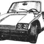 MEET: “SPORT-TOURIST”
Central to the exhibition NTTM-82 this car attracted the attention of visitors not less, than standing next to the new "Lada" with a rotary engine. It is not surprising, because it very...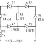 UNIVERSAL INDICATOR
Two LEDs with different color (e.g., red and green), you can build a simple indicator for voltages from 4.5 to 220 V. It is also able to determine the polarity of the source in the range...
