My technical creativity began as far back as I can remember. Of course, it all started with models and various useful things. My simple crafts were born at the end of the common yard, in the storage room. I had to be happy with such a place: after all, others didn’t even have a roof over their heads. After getting acquainted with “M-K” in 1965, my first serious project emerged—a scooter with a D-4 engine and wheels from a scooter. It looked like a miniature “Vyatka.” Then there were publications about E. Molchanov’s “Muravey,” Chumichev’s amphibian, and the “Automule.” They inspired me to think about building a car of my own design. I had little knowledge, couldn’t weld, and critically lacked parts, but I still started…
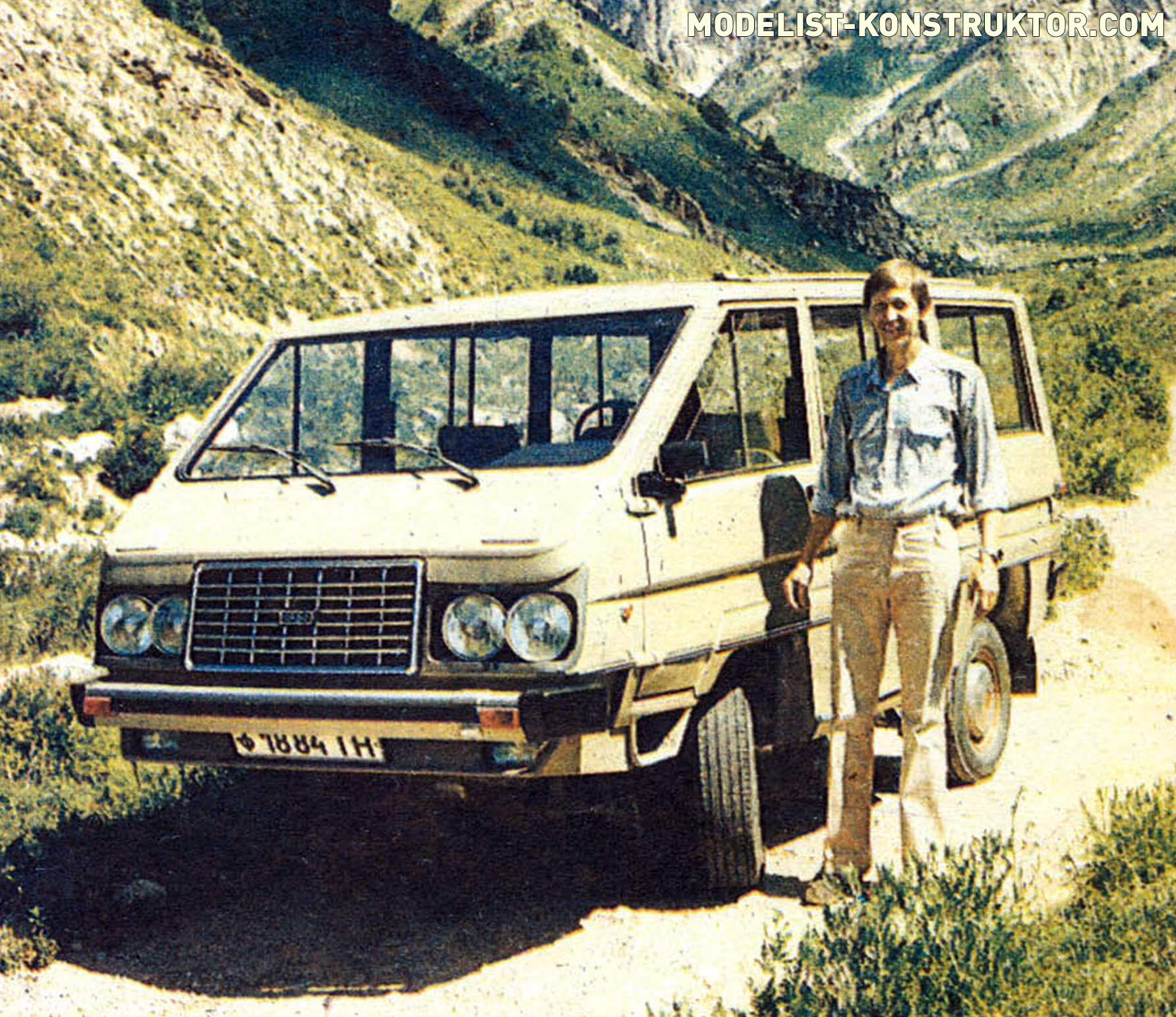
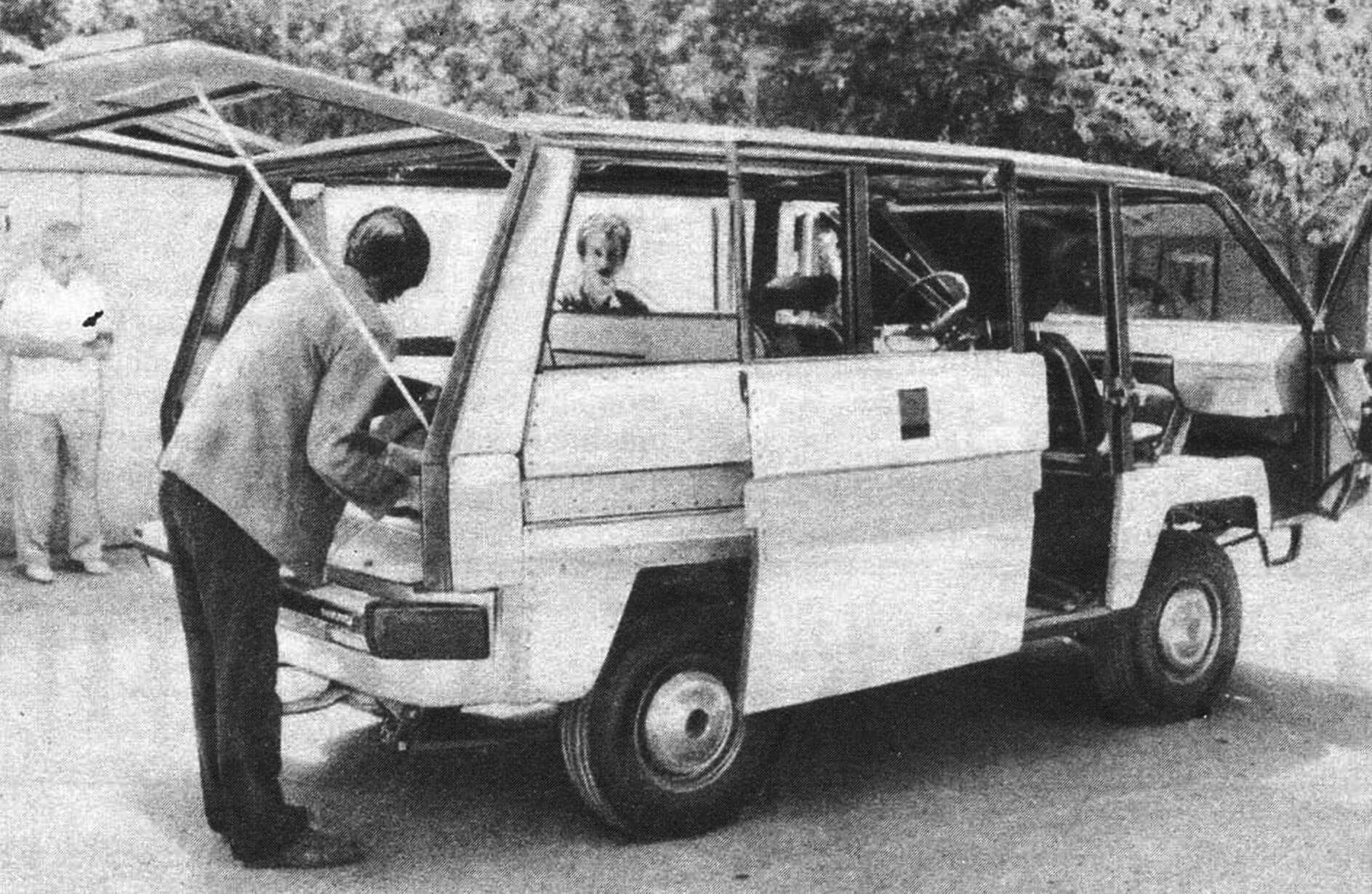
It took seven years to build the car, and in 1977, I received a technical passport and license plates for the SABS car (the firm “Samodelnye Avtokonstruktsii Bolshakov Sergei”). The frame was welded from Ø 25 mm pipes, the chassis from channel № 6, and the body was covered with 3 mm thick textolite and tarpaulin. The chassis parts were assembled from units of SAZ and ZAZ. The body type was “wagon.” It was probably the happiest car in the city of Tashkent. All drivers and pedestrians smiled when they met it, which brought me great pleasure. The car covered more than 35,000 kilometers, revealing many miscalculations and shortcomings that I really wanted to fix. Therefore, with the experience gained, the only option was to start creating a new, more advanced model.
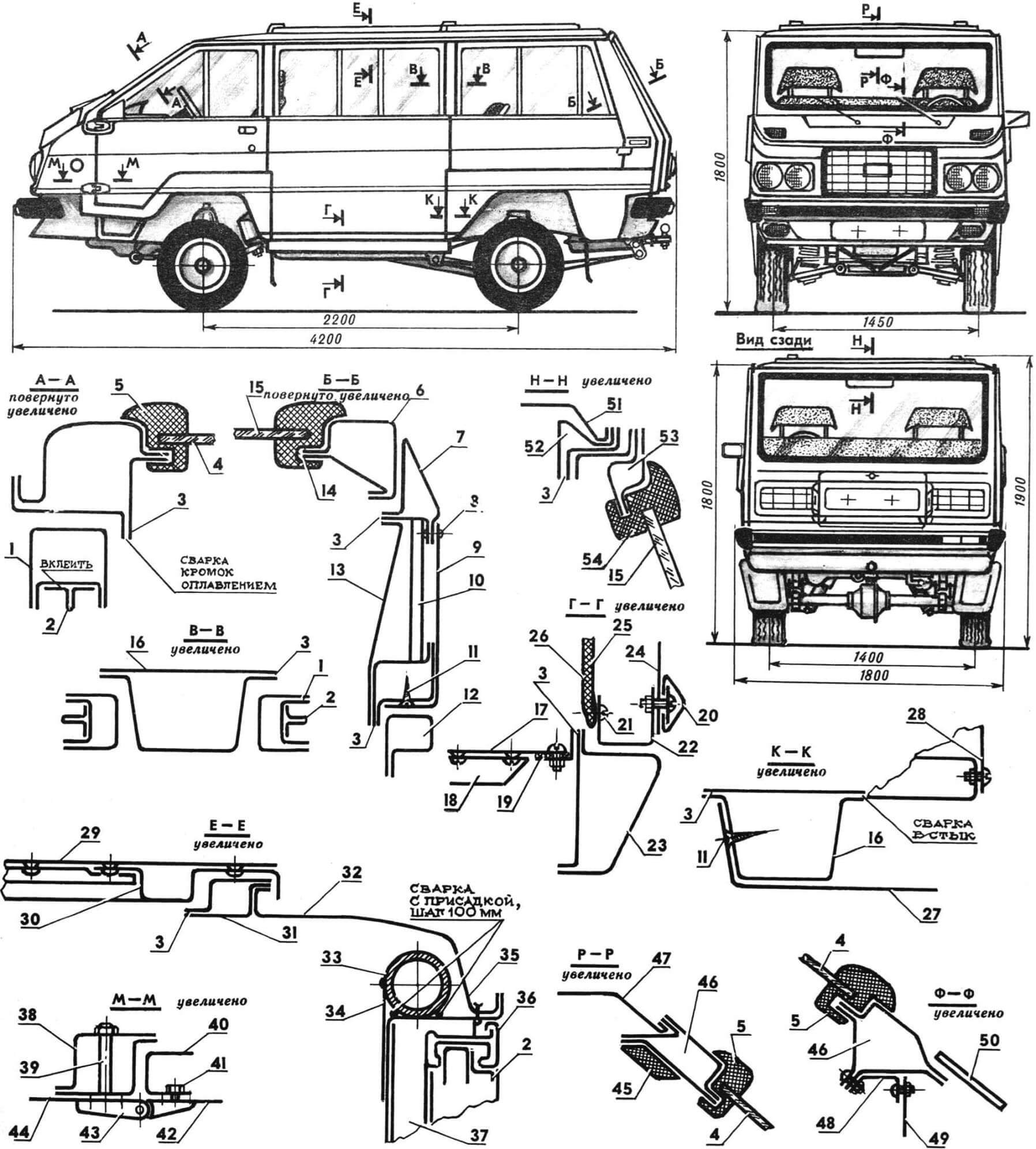
1 — door frame (St. 3), 2 — glass divider, 3 — door opening sealing bead, 4 — windshield glass, 5 — windshield sealing (from VAZ-2101), 6 — rear glass frame, 7 — pillar, 8 — rivet, 9 — outer cladding (D16AM), 10 — reinforcing channel (1.2X15X30 mm), 11 — “self-tapping screw,” 12 — rear side door frame, 13 — inner cladding (D16AM, attached under the door seal), 14 — rear glass sealing bead, 15 — rear glass, 16 — middle pillar, 17 — floor (D16AT), 18 — floor stiffness rib (D16AT), 19 — rubber seal, 20 — molding (from VAZ-2101), 21 — clip of inner cladding, 22 — middle door frame (St. 3), 23 — threshold (St. 3, thickness 1.8…2 mm), 24 — outer cladding (D16AT), 25 — inner cladding (D16AT, thickness 0.8 mm), 26 — decorative finish (artificial leather, foam rubber), 27 — fender (D16AT), 28 — fender liner (D16AT), 29 — hatch cladding (D16AM), 30 — hatch cladding (D16AM), 31 — hatch opening trim (St. 3), 32 — longitudinal roof cladding panel (St. 3), 33 — longitudinal frame (thin-walled pipe Ø 35 mm), 34 — reinforcing overlay, 35 — gutter, 36 — glass frame, 37 — side pillar, 38 — front door pillar, 39 — pipe, 40 — door trim, 41 — bolt, 42 — door cladding, 43 — door hinges (from IZH-“Kombi”), 44 — body side cladding, 45 — gasket (foam rubber), 46 — windshield trim, 47 — roof cladding, 48 — connecting plate (D16AM), 49 — front shield (D16AM), 50 — wiper panel, 51 — roof cladding, 52 — roof trim, 53 roof frame, 54 — rear door seal.
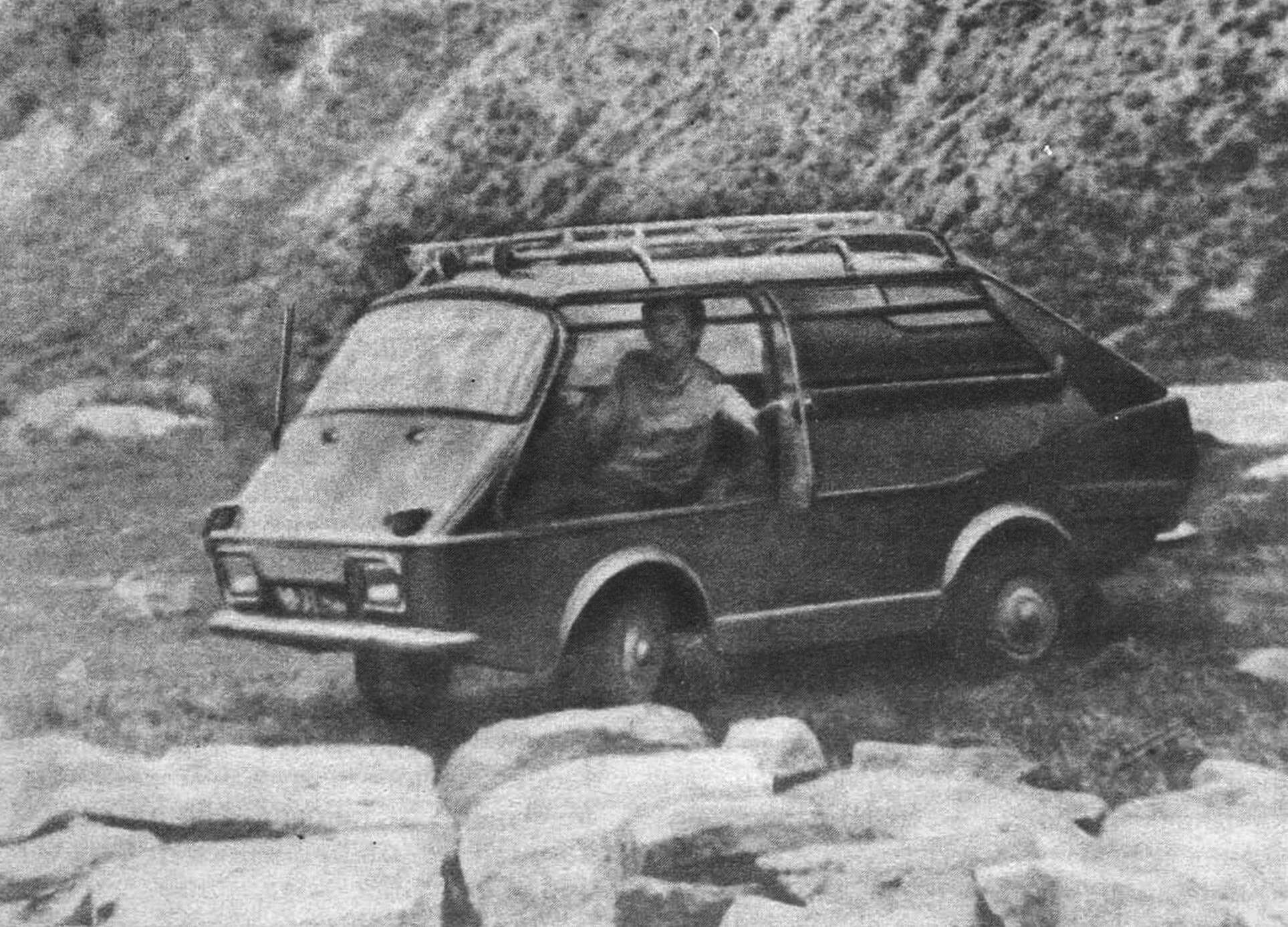
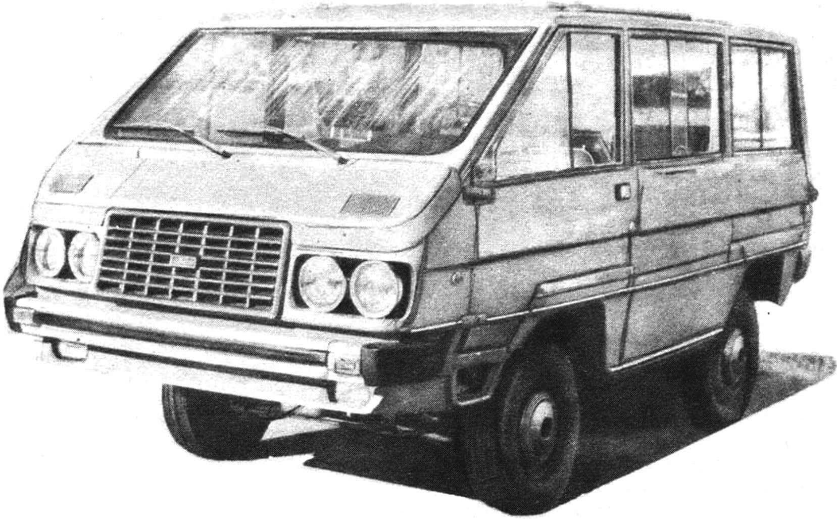
SABS-2 was conceived as a five-seater tourist car, with two sleeping places on the roof in a tent and three in the cabin. Like the first one, it took seven years to manufacture. They were very difficult years, but if I were offered to start all over again now, I would undoubtedly repeat them. However, I would like to warn novice DIYers that you can embark on such work only with a clear understanding of the following issues. Firstly, why are you building a car, and consequently, what type it is and where it will be used. Secondly, “what are you making it from,” therefore, what materials, parts, and assemblies you use, as well as the technologies. Thirdly, which is also crucial, where you are building the car—considering factors like neighbors, weather, distance from home, and not forgetting your family. And the last question is finances: don’t be deceived that a DIY project will be cheap—it’s not. If you want to end up with a good product, it will require a significant investment.
And now, more details about the construction (perhaps someone will find my experience useful, and it will lay the foundation for their ideas and solutions).
The main body sections are marked in the drawings of the general view. Specific dimension values on them (and the frame sketch) are not indicated since they depend on the available material and the dimensions of the car. What I like most about the design is the principle I implemented: complex configurations are obtained by assembling simple ones. Moreover, as needed, volumetric elements can be made from materials of different thicknesses. This results in a reduction in the overall weight of the structure. The elements are connected using gas welding, mainly without filler, by melting the edges. Before welding, the parts are assembled and clamped together with clamps at intervals of about 100 mm. Points are welded between the clamps, and then after removing the clamps, the entire seam is welded. Sometimes during assembly, it turns out that two, three, four, or more layers are joined (for example, sections P-P, E-E, N-N); in this case, “points” are created by melting the edges, and the seams are welded with filler wire.
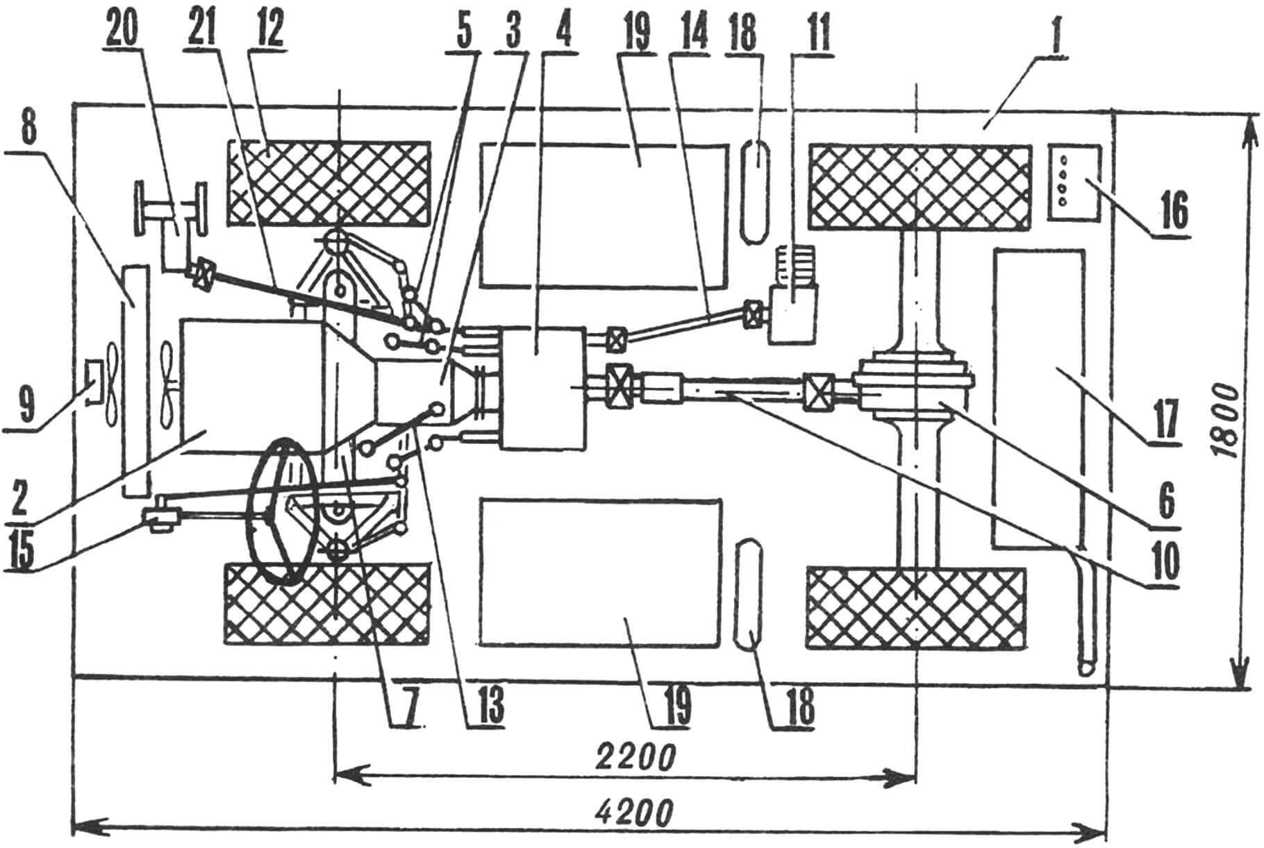
1 — body, 2 — engine (from GAZ-24), 3 — gearbox (from GAZ-24), 4 — transfer case (own design), 5 — transfer case control levers, 6 — rear axle (from GAZ-24), 7 — front axle (from GAZ-24), 8 — radiator (from VAZ-2121), 9 — radiator electric fan (from VAZ-2106), 10 — propeller shaft (from GAZ-21), 11 — compressor. 12 — wheel (from GAZ-24), 13 — gearbox lever, 14 — compressor drive propeller shaft, 15 — steering mechanism (from GAZ-24), 16 — 6CT60 battery, 17 — fuel tank (capacity 75 liters), 18 — receiver, 19 — driver’s and front passenger’s seat, 20 — winch, 21 — winch shaft.
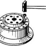
In the manufacturing of construction elements, a homemade sheet bender was used. It was made from two beams, each 1600 mm long (channel № 12, welded into a box), connected along the edge with loops. One of the beams is rigidly fixed on supports, and the other has two handles with a diameter of 30 mm and a length of 700 mm. The workpiece is pressed against the fixed beam with a plate measuring 16x120x1600 mm with a 45° chamfer. The plate itself is fixed with four clamps attached to the fixed beam with bolts. Straight bends are performed by turning the movable beam using the handles, and reverse bends are done in the same way, with the details (depending on the section) clamped through pads of varying height. Wooden, steel, or other strips of the required size and length are used as these pads. With this device, I bent steel sheets with a thickness ranging from 0.1 to 1.5 mm and a length of up to 1600 mm alone. The parts turn out to be so high-quality that they do not require additional correction and puttying.
All cladding elements, the floor, and the roof are made of aluminum alloys—this is advantageous both in terms of weight and corrosion resistance. However, there is a drawback—it is challenging to paint. To obtain a high-quality surface, the parts need to be anodized beforehand. This operation was performed for me at the Tashkent Aircraft Plant.
The cladding was attached to the steel frame using various methods—rivets, screws, and “self-tapping screws”—each chosen for its technological characteristics. To prevent electrochemical corrosion due to the heterogeneity of materials, all joints between the body and the frame were coated with anti-corrosion mastic before assembly.
If someone has doubts about attaching cladding parts with screws, I want to dispel them in advance—door cladding, for example, is fully assembled with concealed M3 screws at a pitch of 50…70 mm. After assembly, the inner surface must be covered with soundproof anti-corrosion mastic. Since the threads of the screws are filled with this mastic, they will not loosen due to vibrations and will not rust due to moisture. Places of countersinking before installing screws with a concealed head were primed, and the fasteners were tightened on “raw” paint.
When designing the car, consideration was given to future possible repairs because nothing lasts forever. Moreover, as statistics show, once every 10–15 years, if not you, someone might “smooth you out.” Therefore, I can confidently state that homemade designs must be large-module. In my variant, this is clearly seen. The car has seven doors: three of them are working doors, and four are detachable with bolts. The upper bolts of the rear door serve as hinges and allow it to be opened together with the blocks of the rear signal lights. The middle, right-hand door, has one hinge and a correcting cable, allowing you to open the entire opening, “taking” the door parallel to the body at a distance of half the width of the door: in cramped parking conditions, this option is very convenient. The front part of the body, along the axes of the front door hinges, is detachable and fixed with six M10 bolts. The rear part, below the edge of the rear door, is also detachable. The wings are also repairable: they are attached to the frame using pads made of porous rubber with “self-tapping screws” at a pitch of 70…100 mm. The body itself is secured to the frame with eight studs Ø 16 mm with M12 threads through rubber cushions. The latter, for ease, are made hollow.
Inside the cabin, there are two rows of seats. The first consists of two single seats, and the second of one double and one single seat. Since the car is intended for long-distance travel, the number of seats is designed for five people. However, the interior volume allows for the installation of an additional row of passenger seats. In my case, the second row is made transformable—folding the seats creates a cargo platform with dimensions of 1730×2300 mm, which serves as a sleeping space during a trip. If only the single rear seat is converted into a sleeping position, it provides an opportunity, with two drivers on the trip, to allow one of them to have a full rest without stopping the vehicle. A rested driver, as is known, is a guarantee of safety.
A significant challenge in cars with a wagon layout and a front-mounted engine is related to the installation and removal of the power unit. In the SABS-2, this is taken into account. I perform the installation and removal of the engine, along with the gearbox and transfer case, alone. For this purpose, a removable device is provided in the cabin. Opposite the right, first middle pillar of the body, along the course, there are attachment points for a swivel crane-beam. With the front seat removed using a winch mounted on the crane-beam, the entire power unit is extended through the middle door and lowered to the ground. Assembly is carried out in the reverse order. The serviceability of the engine is facilitated by the removable floor of the cabin, covering it from above; this solution allows, in most cases, to do without a service pit or a ramp.
The transfer case serves for reduced gearing, and effectively the car has not five “speeds,” but ten. In addition to this, the transfer case has a power take-off shaft for the compressor and winch drive, which can be engaged both in park and during movement. The design of the transfer case is homemade, similar to the GAZ-51. It is based on two shafts, one of which is splined to the secondary shaft of the gearbox and ends with a gear (all gears used are spur gears). The second shaft is coaxial with the first and has a “floating” external meshing gear on splines. The gear modules are identical.
The movement of gears on the shafts is carried out by three independent forks attached to three shafts. The latter are located along the shafts and have the ability to move in the longitudinal direction, choosing the required position and locking with special locks.
The gearbox housing is assembled from 16 mm thick duralumin plates. Sealing is provided by M8 bolt clamps. After assembly, holes for mounting the bearing supports on the shafts are jointly reamed in the walls. The plates must be dowelled before performing this operation.
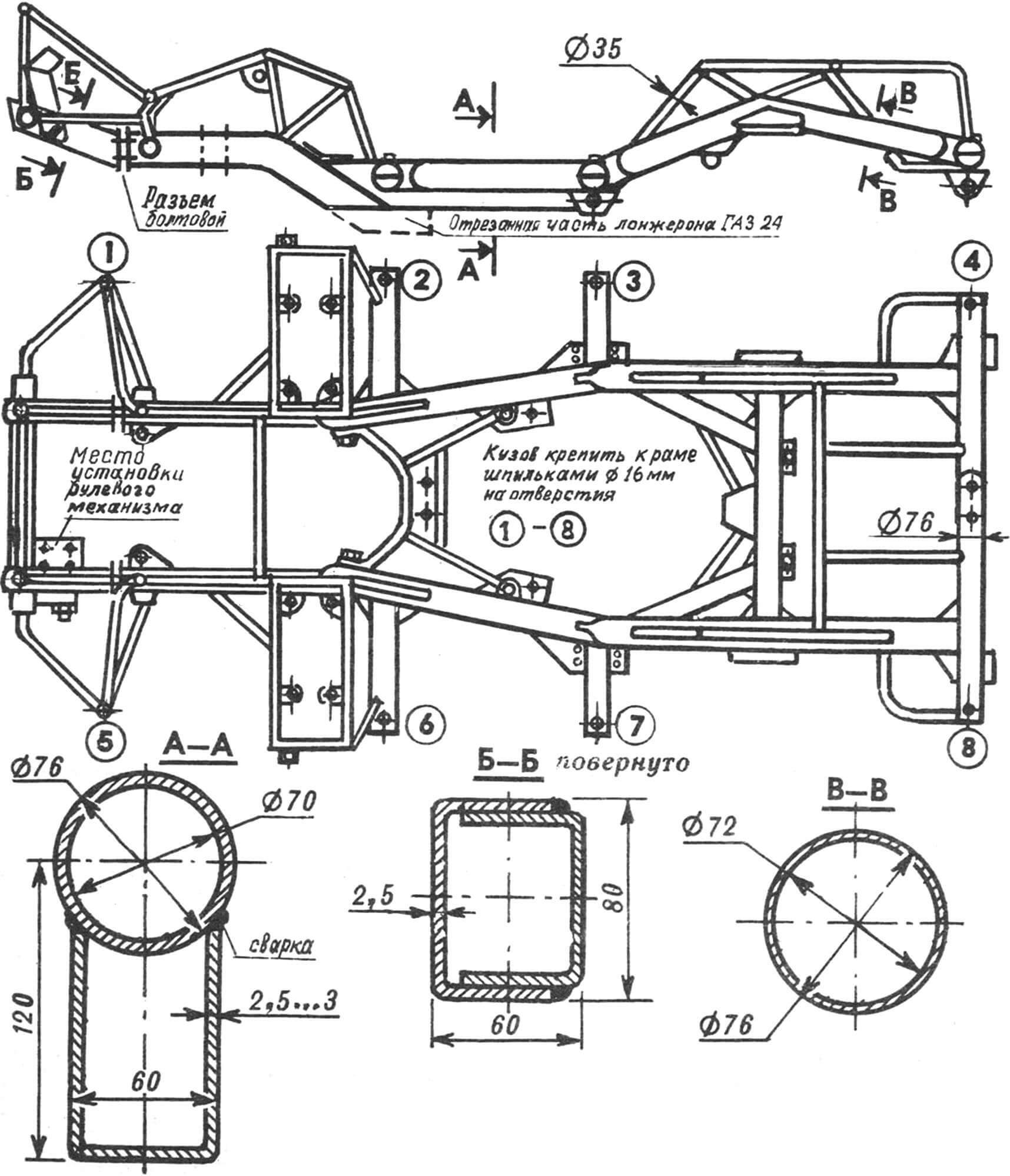
Most of the chassis components (front suspension, rear axle, leaf springs) are borrowed from the GAZ-24 car. In the brake system, a power steering unit from the VAZ-2106 is used together with the main brake cylinder from the GAZ-24, connected through an adapter. Tie rods and the steering mechanism are also taken ready-made from the “twenty-four,” with the addition of an additional longitudinal tie rod and a pendulum lever from a worn-out steering mechanism. From it, only the sleeve, bracket, and axis with conical splines are left. A lever ending with a hole for the longitudinal tie rod is fastened on bolts M12 from three sides into the milled socket instead of the roller. The steering mechanism itself is located at the front of the frame on a bracket fixed with two M16 bolts.
To ensure passive safety in the car, there are seat belts, energy-absorbing bumpers with hydraulic drives, soft interior trim, and protruding interior details, as well as safety arcs. The latter are formed by powerful pillars and structural elements of the roof.
Ventilation of the cabin is carried out through windows and roof hatches equipped with electric drives. Double worms from windshield wiper gearboxes are used for this purpose. For heating the cabin, two water heaters connected in series are used. One is located in front of the cabin under the windshield and draws in outside air through a collector. Its area of effect includes the driver’s and front passenger’s seats, as well as the windshield and front side windows. The second heater is located between the front seats and passes only cabin air through itself, thereby providing comfortable conditions for rear passengers.
Planning long journeys through desert and mountainous terrain, additional amenities were provided in the minibus—water tanks for drinking water, as well as four headlights with the ability to swivel, tracking the position of the steering wheels with a lever. When driving in normal urban conditions, the headlights are fixed in the central position. Fog lights are located at the bottom of the body.
So, that’s mostly all I wanted to tell about my car. In my opinion, in the scope of a magazine article, it’s unlikely that a more detailed description of such a complex structure is necessary: for those who don’t understand the technique and don’t have a penchant for DIY, even the most detailed description, down to the last screw, will still be of little use. On the contrary, a passing mention of a solution can help a creative person in their quest. I think real DIY enthusiasts understand me.
And one more appeal to readers, owners, and authors of cars designed, like my car, for long trips. Isn’t it time for us to gather and organize a joint road trip? How about embarking on a journey, for example, through the countries of Europe? Or organizing the “journey of the century” on DIY vehicles along the Silk Road, from Tashkent to Beijing?
In short, if you have thoughts on this matter, write to the editorial office, in the comments, or to me, at the address: 700060, Uzbekistan, Tashkent, Kl. Tsetkin Street, Building 16, Apartment 24. To Sergey Konstantinovich Bolshakov.
S. BOLSHAKOV
Recommend to read
 THE WHEEL IS NOT INVENTED, AND MADE
Whatever you say, the main and most available in the production of multigrade engine homemade all-terrain transport vehicles remains pneumatic— wheel with low tire pressure. But for a... BUS… “AVOSKA”
We used to go fishing. On the distant lake, where pervalence always well caught pike and large perch. Our experienced "Muscovites" cheerfully rolled down the snowy highway. Quietly...
