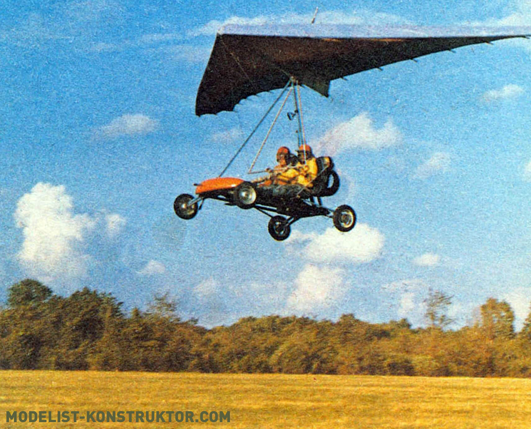
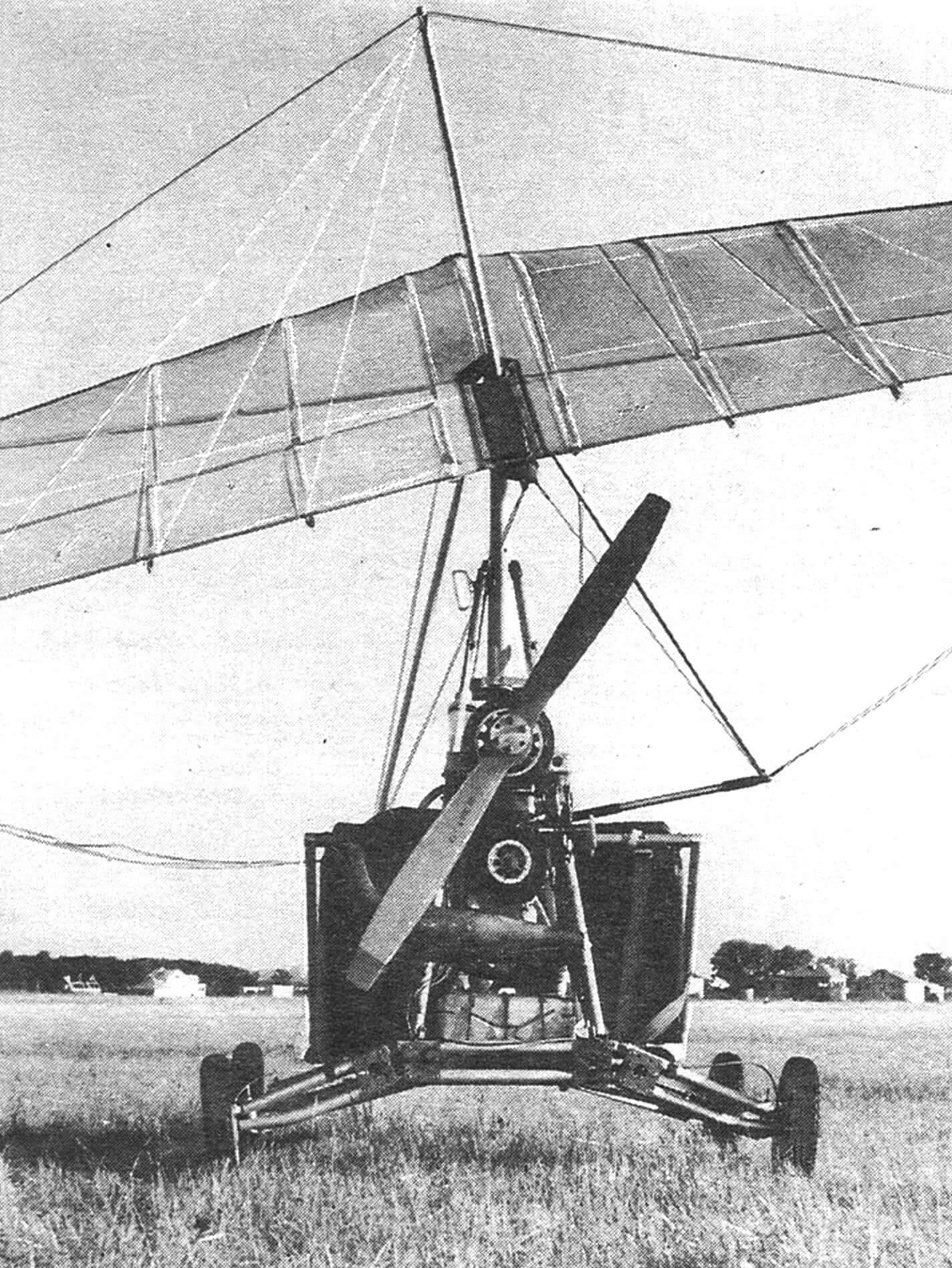
By experience, we know that the appearance of the “Beetle-42” delta wing aircraft evokes many emotions and, naturally, questions. Let’s set aside the emotions and focus on the most significant question: why does it have a four-wheel chassis instead of a three-wheel one?
Before answering, let’s recall that ground vehicles with three-wheel chassis and front-wheel steering are unstable on turns and uneven terrain, prone to tipping over. The same can be observed in three-wheeled delta wing aircraft, especially during critical phases like takeoff and landing, and especially on unprepared surfaces. As practice shows, no one is immune from tipping over: neither a novice nor a master.
So, what’s the reason? The reason lies in the fact that the traditional three-wheel or, as they say, classical chassis of a delta wing aircraft is very sensitive to longitudinal and lateral tipping moments caused by the inertia of the high-mounted wing with significant mass when the vehicle moves on uneven terrain. These moments act around the tipping axes connecting the center of the front wheel with the centers of the rear wheels. During straight-line movement of the delta wing on level ground, the forces trying to tilt it right or left are in equilibrium and cancel each other out. However, with the slightest bump under the front wheel not strictly along the longitudinal axis of the vehicle, the delicate balance is disrupted, and an uncompensated moment around one of the lateral tipping axes is formed. Pilots of three-wheeled delta wing aircraft know that the critical speed in this regard is around 45-50 km/h.
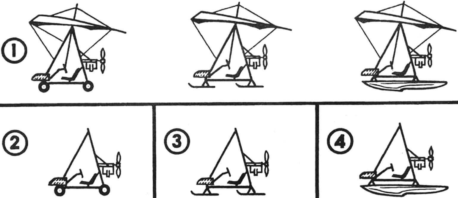
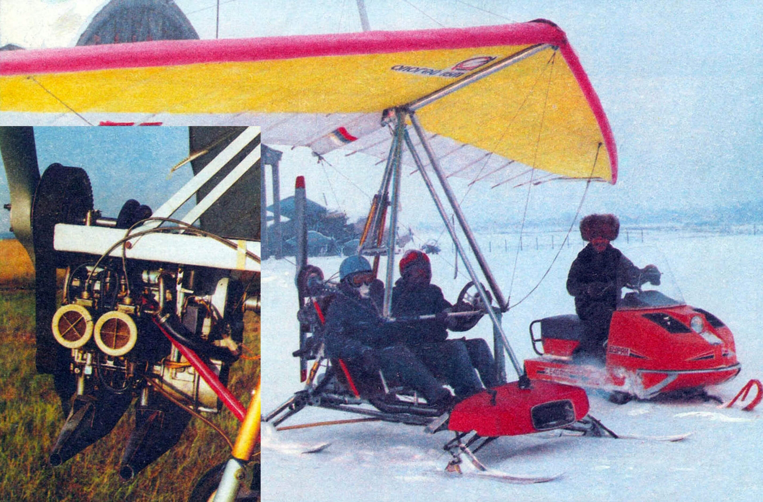
1 — delta wing with wheeled, ski, and float chassis, 2 — aeromobile, 3 — aerosled, 4 — aerocatamaran.
One of the most effective ways to improve the stability of the delta wing during takeoff and landing is to use a fourth wheel. In a four-wheel chassis moving on uneven ground, tipping moments from the inertia forces of the high-mounted wing are not as dangerous because the tipping axes are far from the center of gravity. On level ground, such moments do not occur at all.
Of course, the new scheme is not without drawbacks. For example, the design of the motorcycle carriage becomes more complex, and its weight increases.
How much? Calculations show that the steering mechanism, telescopic column with cardan joints, reducer with rods, and the fourth wheel with its mounting unit add 5% to the takeoff weight of the “Beetle.” This is insignificant considering that on the other side of the scale is increased stability and, consequently, safety.
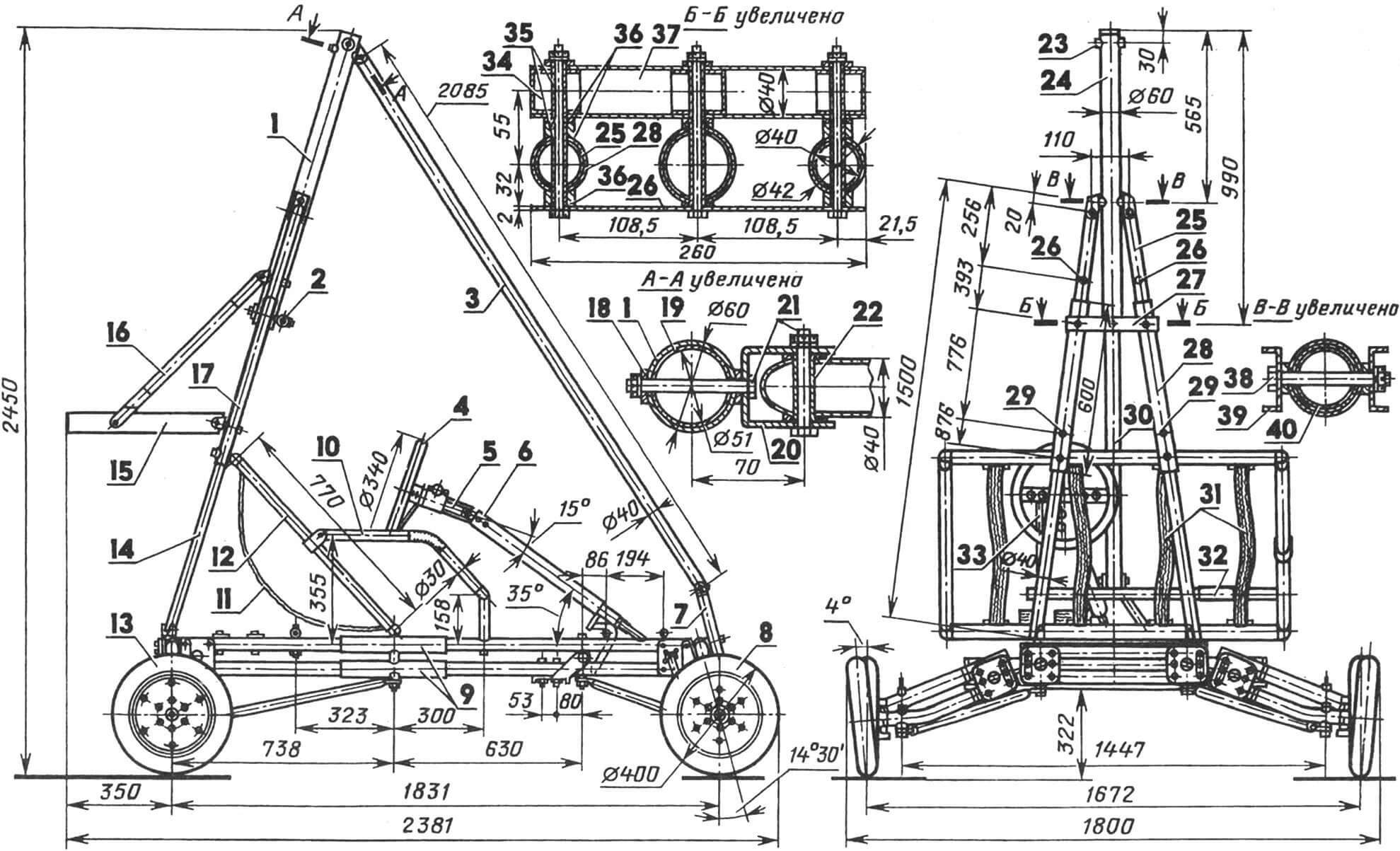
1, 24 — upper mast pylon, 2 — lock, 3, 30 — front pylon, 4 — steering wheel, 5 — steering mechanism hub, 6 — telescopic steering column, 7 — pylon support, 8 — front wheel, 9 — longitudinal reinforcement tubes, 10 — passenger seat armrest, 11, 31 — seat belts, 12 — seat frame, 13 — rear wheel, 14, 25 — right mast strut, 15 — motor frame, 16 — motor frame rod, 17, 28 — strut reinforcement tube, 18 — shaped washer, 19 — upper pylon reinforcement tube, 20 — mounting ear, 21, 38 — M8 bolts, 22 — rivet bushing, 23 — hole for wing joint attachment, 26, 29 — holes for motor frame attachment and its rods, 27 — lock plate, 32 — passenger seat handle, 33 — steering support, 34 — plug, 35 — rivet bushings, 36 — shaped washers, 37 — lock tube, 39 — strut mounting ear, 40 — reinforcement tube (length 250 mm).
What else? The front axle increases frontal resistance, leading to additional fuel consumption. However, this can be accepted considering the advantages of the new chassis scheme. Here’s one of them: unlike a delta wing of the classical scheme with a single front wheel that hardly protects the crew in a collision, for example, with a tree, the “Beetle” has a front axle that can act as a bumper, absorbing the impact.
Furthermore, the scheme allows for a successful arrangement of seats side by side and at the same level. The low center of gravity of the crew is another factor in increasing the stability of the apparatus. This allows it to be used for training purposes.
If you closely observe novice pilots, it will become clear that the majority possess driving skills, and pedal control of the front wheel in a delta wing aircraft of the classical scheme poses a certain difficulty for them. Not only during the learning phase but also beyond. Therefore, in designing the chassis of the “Beetle,” an automotive approach was applied: wheel camber and toe-in, steering mechanism, and pedal control (since the pilot’s feet are free), throttle and brake control were implemented. All of this helped to make the student’s experience closer to the familiar “automotive” one, significantly reduced adaptation time to the aircraft on the ground, and facilitated the most critical flight modes—takeoff and landing. Moreover, the steering reducer significantly reduces effort on the “steering wheel” compared to the classical scheme.
Furthermore, thanks to the same reducer, the front wheels in the air are always oriented according to the flight, contributing to a smooth landing.
And one more thing. The steering wheel is combined with the wing trapeze. Therefore, during takeoff when the wheels lift off the ground and the pilot switches to wing control, there is no need to move hands from one control to another.
For four years, the “Beetle-42” has been flying, and none of the design decisions implemented in it has been questioned so far.
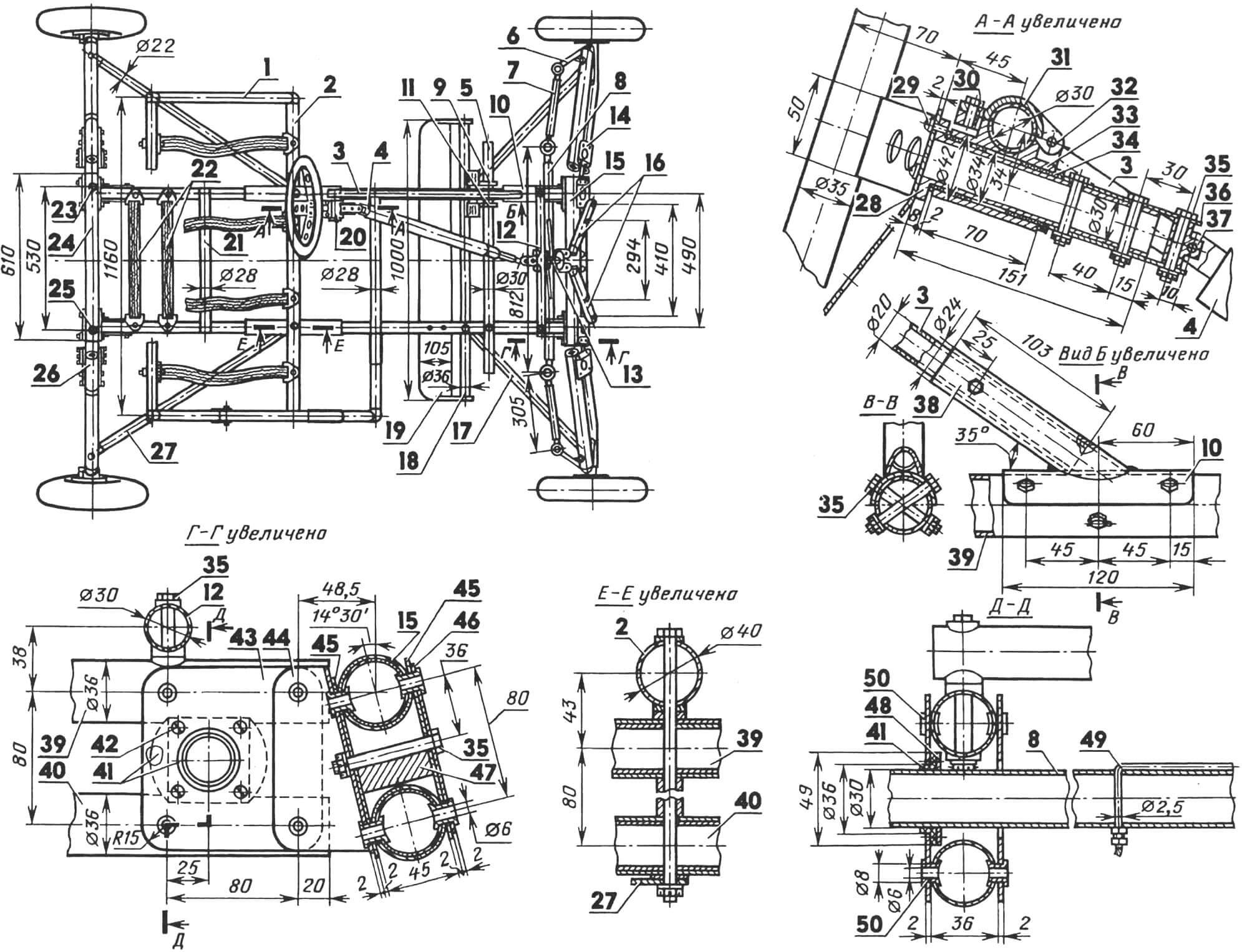
1, 2 — seat frame tubes, 3 — steering support, 4 — telescopic steering column, 5 — pedal travel limiting tube, 6 — swivel pin, 7 — side steering rod, 8 — central steering rod, 9 — brake pedal, 10 — steering support attachment point, 11 — gas pedal, 12 — front crossbar, 13 — steering reducer cable winding, 14 — left front wheel suspension, 15 — front axle, 16 — front pylon struts, 17, 27 — front and rear braces, 18 — load-bearing step tube, 19 — step, 20 — steering mechanism, 21 — rear crossbar, 22 — suspension straps for fuel tanks, 23, 25 — attachment holes for mast braces, 24 — rear axle, 26 — right rear wheel suspension, 28 — steering wheel hub, 29 — M6 screw (3 pcs.), 30 — M6 bolt for steering mechanism hub (2 pcs.), 31 — hub cover, 32 — pivot axis (M6 bolt, 2 pcs.), 33 — hub body, 34 — PTFE bushing-bearing (2 pcs.), 35 — M6 bolt (8 pcs.), 36 — hinge for telescopic steering column, 37 — cardan, 38 — steering support cup, 39 — upper longitudinal tube, 40 — lower longitudinal tube, 41 — PTFE bushing-bearing, 42 — M4 screw (4 pcs.), 43 — longitudinal brace, 44 — angle, 45 — front axle struts, 46 — overlay, 47 — spring, 48 — pressure washers, 49 — steering reducer cable, 50 — tubular rivets.
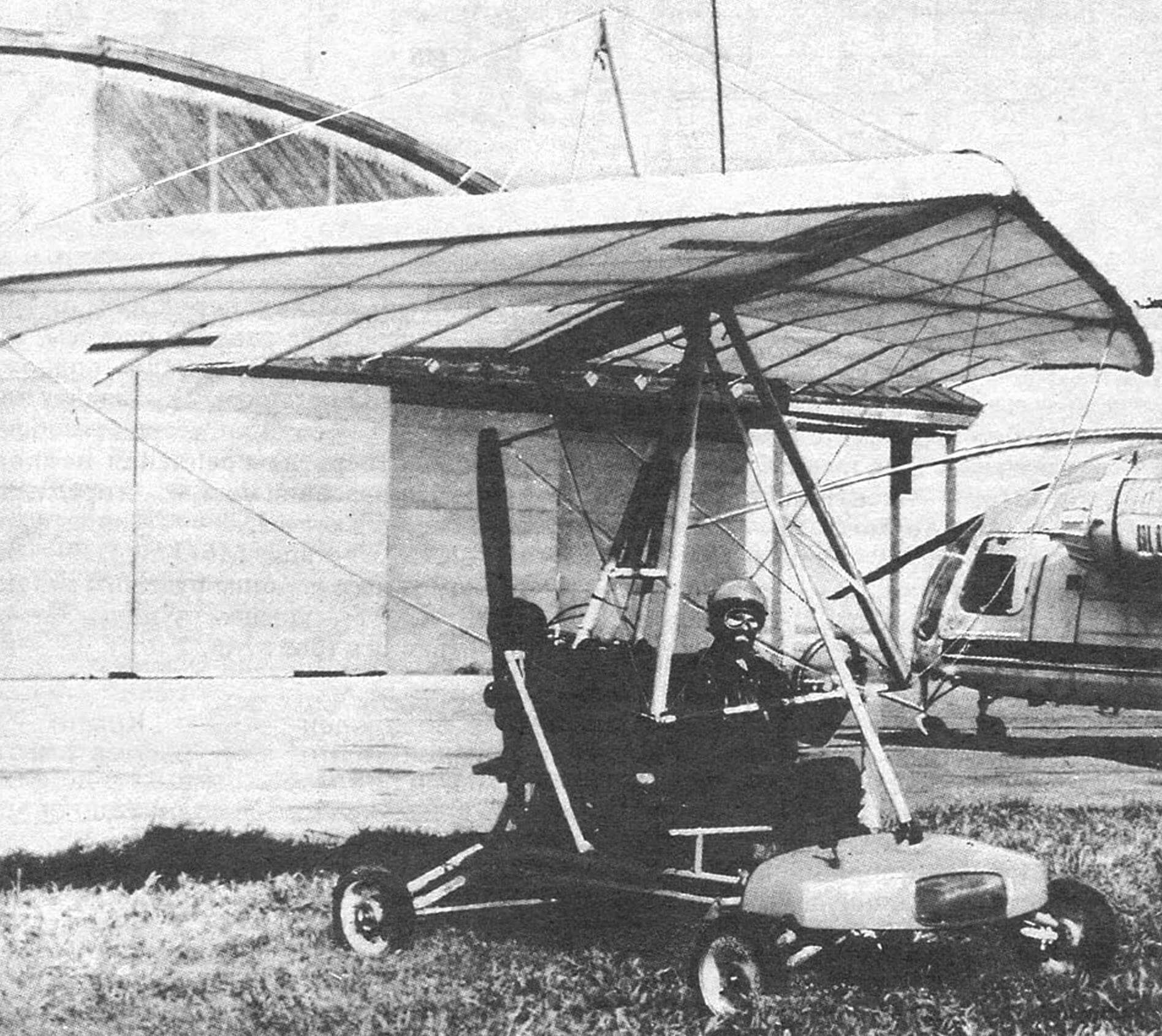
Now, more details about how the delta wing is structured. “Beetle-42” consists of a wing, engine, and motorcycle carriage.
The wing is of the “Apogee-16M” type. Its construction will not be discussed here, as the wing was purchased ready-made from the delta club of the city of Meleuz (Bashkortostan). We will only provide its basic characteristics for information: wingspan — 10.2 m, area — 16 sq.m, aspect ratio — 6.5, sweep — 30 degrees, root chord length — 2.25 m, double skin — 75%.
The engine is of the RMZ-640 type from the “Buran” snowmobile. It underwent such significant modifications that describing them in this publication is not possible. A complete description of the engine upgrade will be presented in a separate article, which will be released in one of the upcoming issues of the magazine.
Here, we will focus on the construction of the motorcycle carriage. It consists of a rectangular frame on which are placed: a front fairing with an instrument panel, pilot and passenger seats, control elements, front and rear wheel suspensions; fuel tanks, batteries, mast for connecting to the motor frame and wing.
Motorcart frame is mainly assembled from aluminum tubes of various diameters (from 22 to 60 mm) with a wall thickness of 1.5 mm. It consists of front and rear axles and longerons. The tubes of the axles and longerons are connected with titanium crosspieces, as well as angles and tubular rivets made of stainless steel. The most stressed areas are reinforced with additional tubes and titanium overlays.
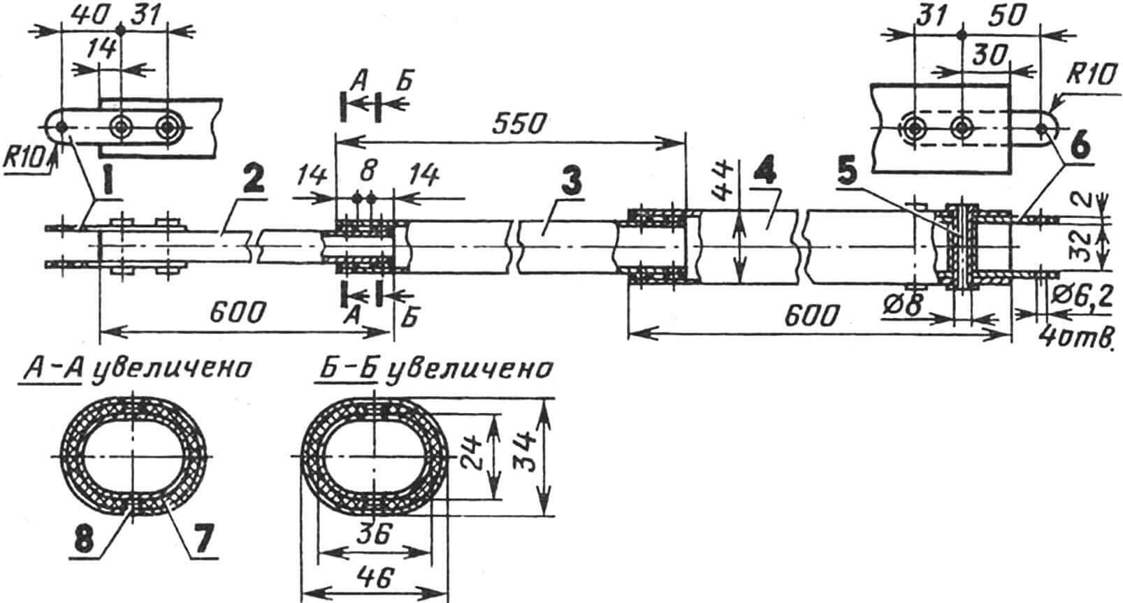
1 — hinges for connection with the steering reducer, 2,3,4 — column tubes, 5 — tubular rivet with reinforcing bushing (4 pcs.), 6 — hinges for connection with the steering mechanism, 7 — PTFE bearing insert (4 pcs.), 8 — rivet (8 pcs.).
Highlighting an important feature of the deltawing design: all bolts on the “Zhuze-42” are splined. A mast is installed at the rear of the frame, which is used to suspend the motorcart under the wing. The mast is composed of two struts, a sturdy upper pylon, and a connecting lock. In the working, slightly inclined position, it is held by the front pylon and the tubes of the seat frame. If necessary, the height of the mast can be reduced by removing the front pylon and disconnecting the lock.
The mast struts are long and heavily loaded by the engine, so they are reinforced in the middle with outer tubes of a larger diameter. The upper pylon is also loaded, so it is a doubled tube, reinforced inside (in the middle) with a segment of a third tube. In addition, it has additional equipment (not shown in the drawings). Firstly, it is a safety cable passed through the pylon: its lower end is hooked to the middle bolt of the lock, and the upper one is thrown over the keel tube of the wing when connecting it to the motorcart. Secondly, a steel block with a diameter of 45 mm, attached to the outside of the pylon by a short segment of the same cable: through it, a cable with a starting handle is thrown and stretched to the engine.
The pylon is attached to the wing by a separate unit, the construction of which will be discussed below.
 Cable Reducer:
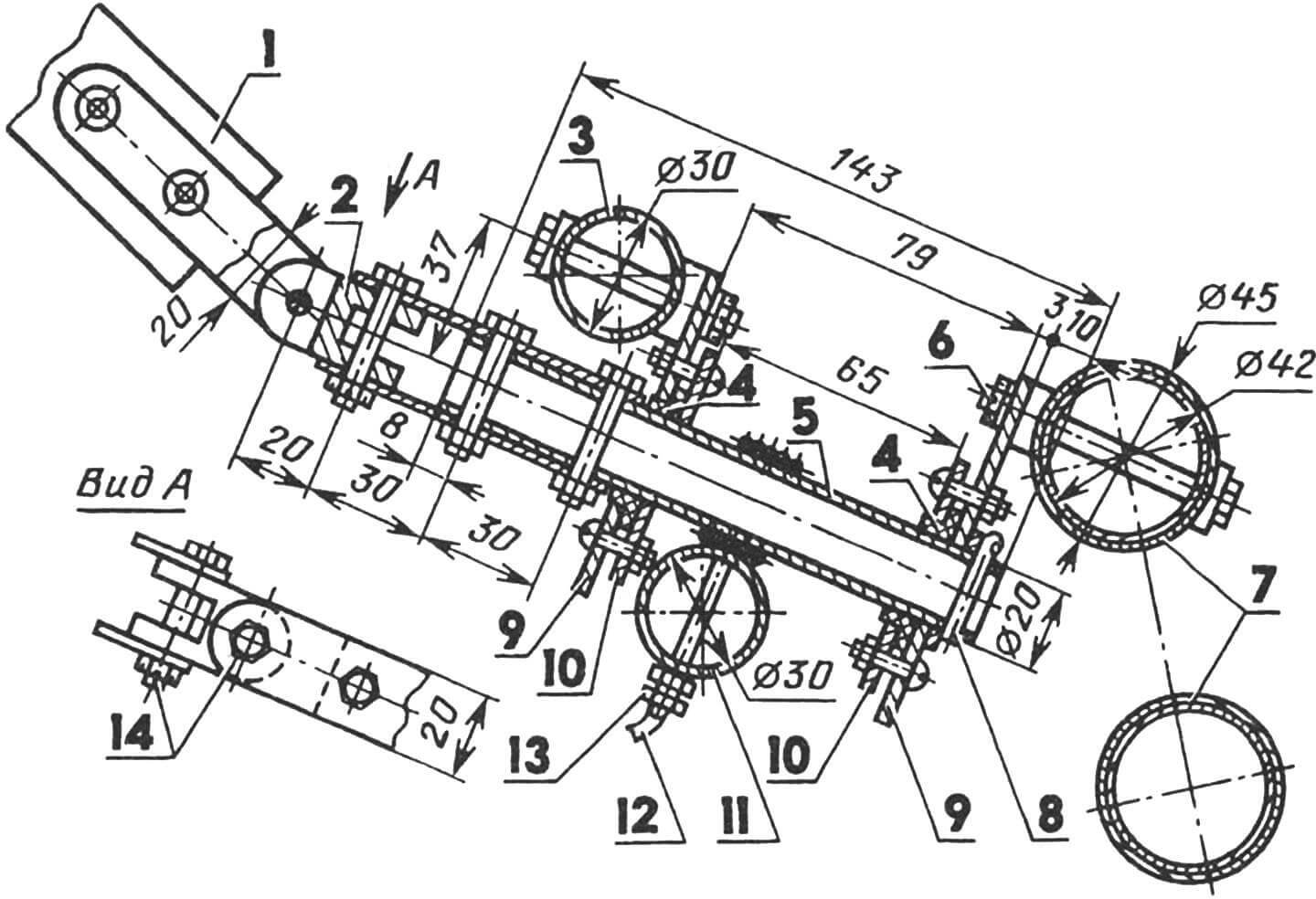
1 — telescopic steering column, 2 — cardan, 3 — front cross member, 4 — nylon bearings, 5 — reducer axis, 6,14 — bolts M8 (8 pcs.), 7 — tubes of the front axle, 8 — splint, 9 — brackets of the reducer axis, 10 — clamping washers, 11 — central steering tie rod, 12 — reducer cable, 13 — cable tension nuts.
The middle part of the motorcart is designed for the pilot and passenger. They are seated on soft (foam padded and covered with leather substitute) seats, resting on the frame straps. Two aluminum tanks (each size — 400x220x180mm) with a total fuel capacity of 34 liters are placed under the seats on the same straps. They are attached to the rear cross member and the axle with rubber straps. Such tank installation allows safe operation on all flight modes with an overload of up to three “g’s” due to amortization.
In front of the pilot, on the left side, gas and brake pedals are located, as well as a control complex, including a handlebar, steering mechanism, telescopic column, reducer with rods, and a rack (the latter is used on the motorcart without a wing, i.e., in the “aeromobile,” “aerosani,” “aerocatamaran” variants). In the “deltawing” variant, when the wing is attached, the rack is removed, and the steering mechanism is transferred to the wing trapeze. The telescopic column with cardans reliably and smoothly transmits the slightest turn of the handlebar over a wide range of steering trapeze deviations.
During the movement of the deltawing, the passenger’s legs are placed on a wide footrest, and the hands are on the armrest. Like the pilot, the passenger is secured to the seat with safety belts (not shown in the drawings).
 Dashboard:
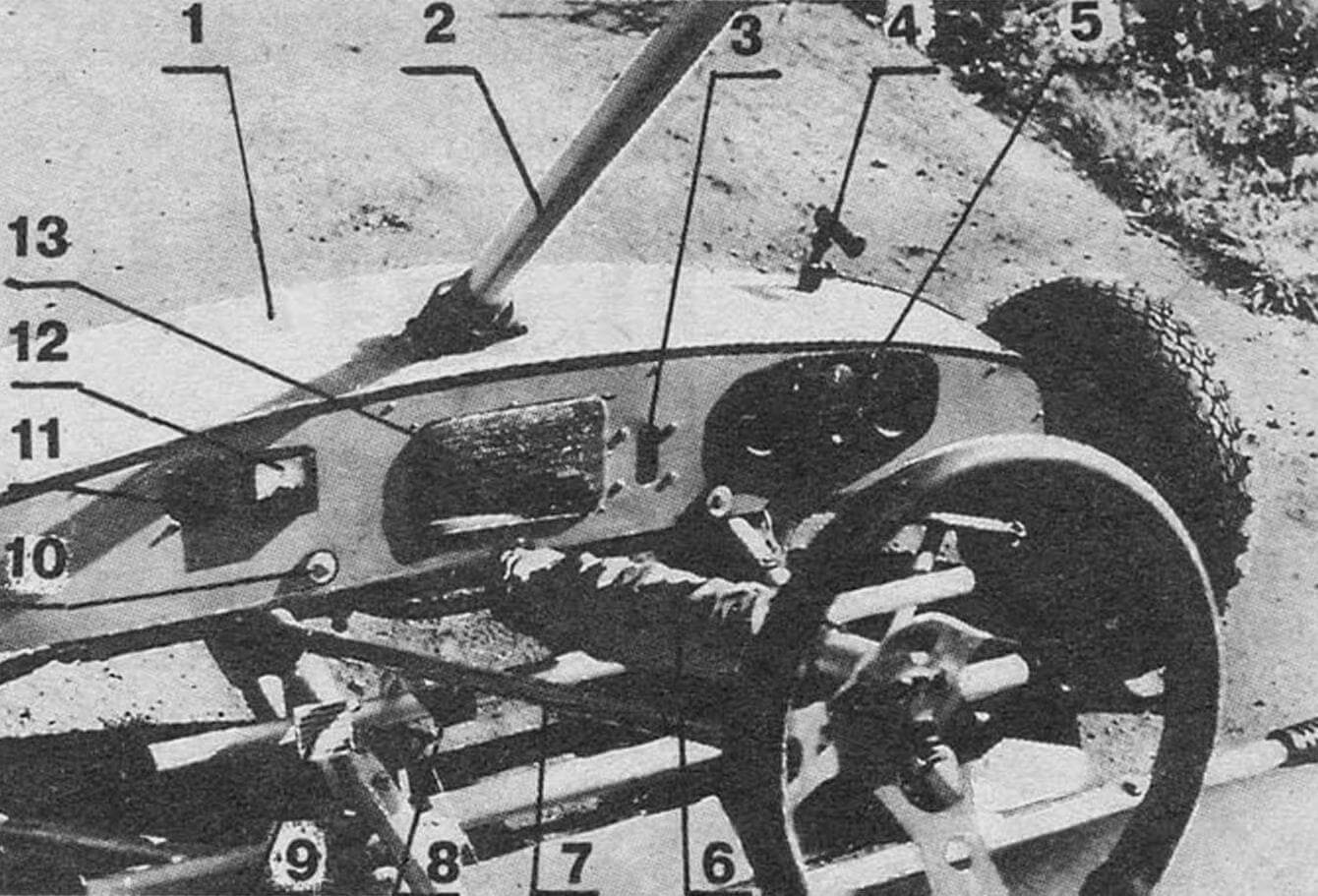
1 — nose fairing, 2 — front pylon, 3 — engine coolant circulation indicator, 4 — air pressure receiver, 5 — instrument block (aviation compass, variometer, altimeter, airspeed indicator), 6 — telescopic steering column in a cover, 7 — steering rack, 8 — gas pedal, 9 — brake pedal, 10 — bolt for attachment to the front cross member, 11 — coolant temperature gauge, 12 — tachometer, 13 — mesh of the air outlet window for cooling the radiator.
The steering mechanism and telescopic column are not very complex structurally, so we won’t dwell on them. Let’s focus in more detail on the cable reducer. It consists of a tube that rotates in two nylon bearing bushes, on which a cable with a diameter of 2.4 mm is tightly wound in several turns. The ends of the cable are fastened in two holes in the central steering tie rod, spaced 280 mm apart. Nuts on the cable ends are used to maintain the required tension.
Such a reducer allows you to select the necessary gear ratio, operates almost silently, and, most importantly, is very reliable.
From the reducer, the force is transmitted to the wheels through the steering tie rods and swivels. The geometry of the tie rods, swivels, and turning knuckles is chosen to provide normal “automotive” control on the ground, even at quite noticeable speeds.
With this publication, we conclude the story about the deltawing “Zhuze-42,” started in previous issues of “Modelist-Konstruktor.” At that time, we talked about the construction of the motorcart. Now let’s look at everything related to the power plant.
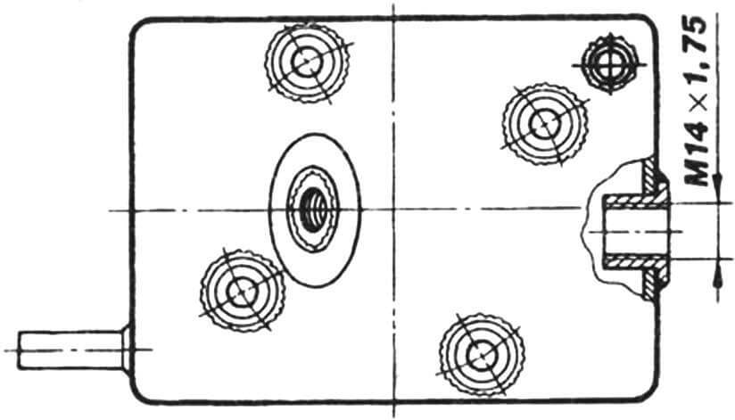
The power plant (PP) of the “Zhuze,” like most aircraft of this class, is located on the mast of the motorcart behind the crew. It consists of an engine, drive gearbox, pushing propeller, fuel, cooling, control, and management systems.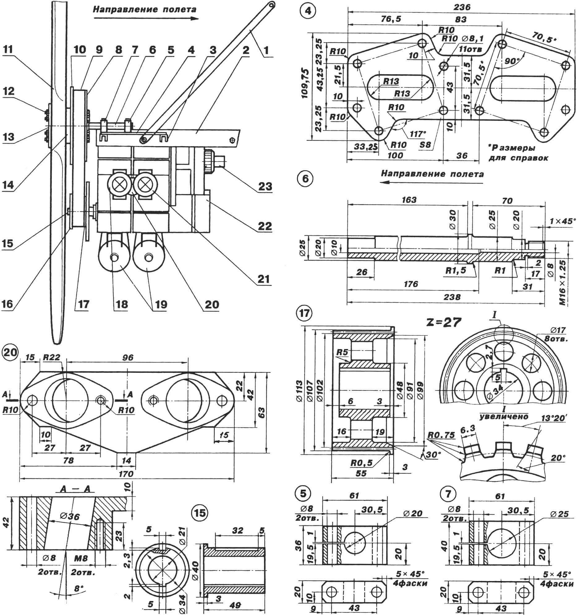 Arrangement of additional equipment on the engine and its frame (except for the liquid cooling system):
1 — frame suspension strut (steel), 2 — side rail (steel), 3 — support beam (titanium), 4 — shaped plate (titanium), 5,7 — front and rear clamps (D16T), 6 — driven gear shaft (titanium), 8 — driven gear of the gearbox, 9 — drive belt, 10, 16 — limiting cheeks of the gears (D16T), 11 — propeller, 12 — bolts M10 (4 — 6 pcs.), 13 — washer (D16T), 14 — spacer (D16T), 15 — spline bushing, 17 — driving gear of the gearbox (D16T), 18, 21 — carburetors, 19 — resonators (steel), 20 — carburetor adapter (D16T), 22 — engine, 23 — pump.
The heart of the PP is the RMZ-640 engine, produced by the Rybinsk Motor Plant and intended for the “Buran” snowmobiles. It is unpretentious, develops significant power, and, moreover, is lightweight. The last two arguments in favor of RMZ-640 make it quite suitable for use on the deltawing. But, of course, in a modernized form, since a purely “snowmobile” engine could not provide the “Zhuze” with acceptable speeds in various flight modes.
What was the modernization?
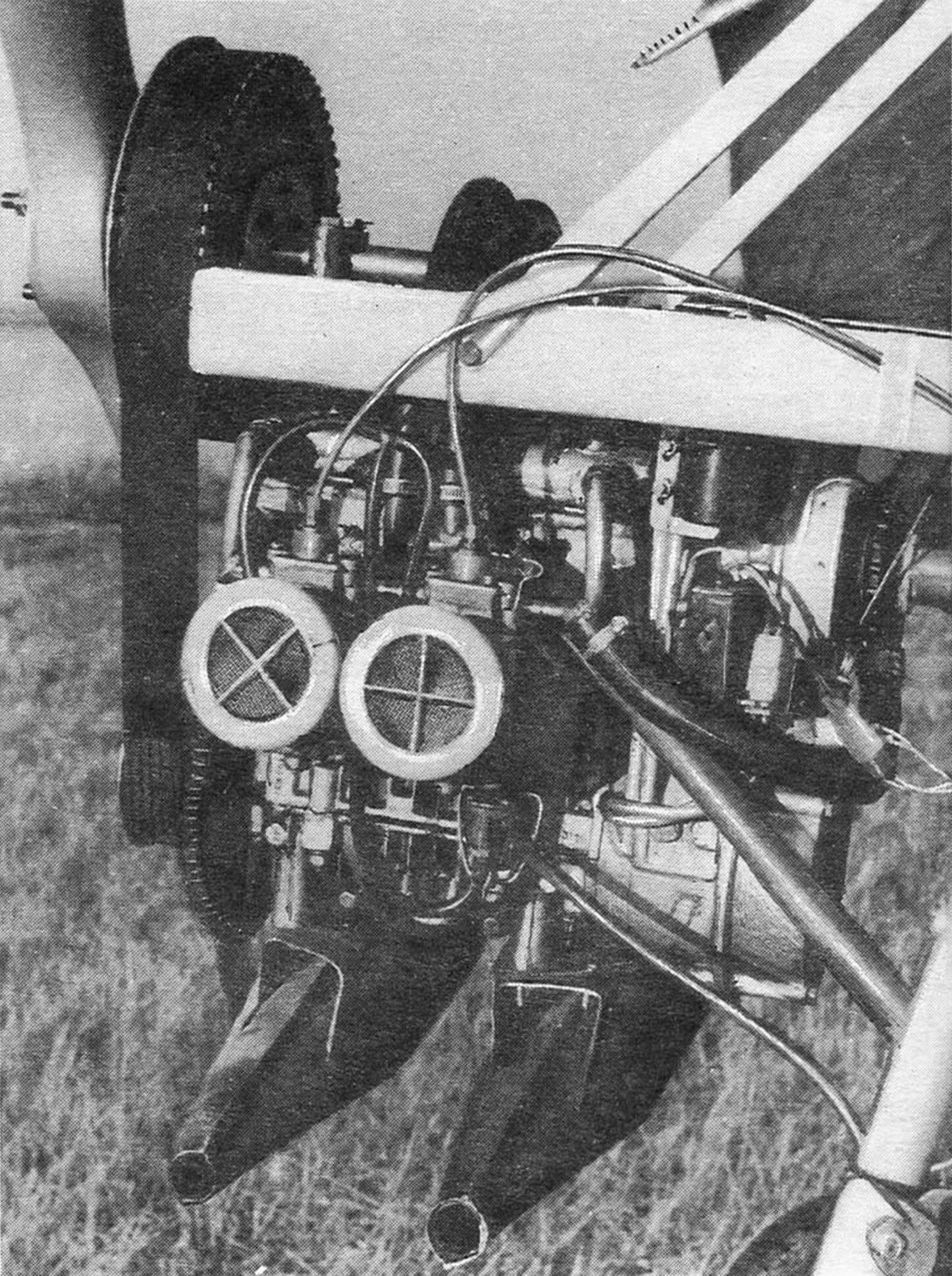
Firstly, in increasing power: a K62I carburetor (from the “Izh-Planeta-5” motorcycle) and a homemade resonator were installed on each of the cylinders. This led to a certain increase in the thrust of the propeller.
Secondly, in the engine conversion from air to liquid cooling, the new operating mode should not result in an increase in the working temperature in the cylinders, preventing them from overheating.
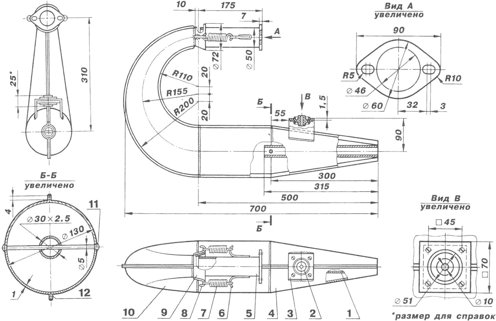
Resonator:
1 — exhaust pipe, 2 — rubber-metal shock absorber, 3 — bracket for attachment to the engine crankcase, 4, 10 — elements of the housing, 5 — pipe connecting to the cylinder, 6, 8 — hooks (4 pcs.), 7 — springs (2 pcs.), 9 — funnel, 11 — rivet rod, 12 — edge of the housing for welding.
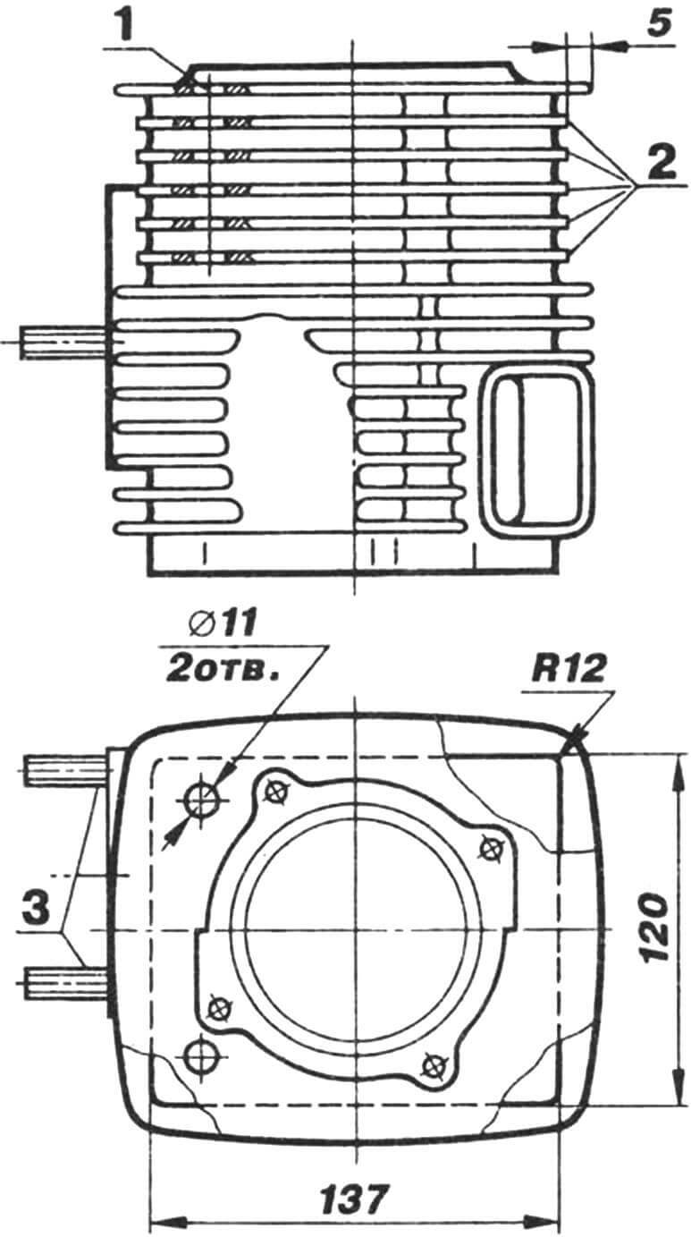
The liquid cooling system required the installation of a radiator (from the VAZ-2108 car), hoses (rubber and polyethylene with an inner diameter of about 20 mm), an expansion tank (1 liter capacity) with soap, a pump (from the NTS-300 car wash), inlet and outlet manifolds, connecting pipes, tees, and clamps. Additionally, modifications were made to the cylinder heads and upper parts of the engine cylinders, equipping them with cooling “jackets.” Initially, six upper cooling fins were drilled for each cylinder (the holes in the topmost were then welded, and the rest now serve as additional channels for the cooling liquid, in this case — antifreeze). Then, the fins from the second to the sixth inclusive were trimmed on all sides and covered with the “jacket” housing — a well-fitted 2mm-thick aluminum strip, welded to the first and seventh fins (counting from the top) by argon arc welding. Two pipes were welded into the strip — for the inlet and outlet of antifreeze.
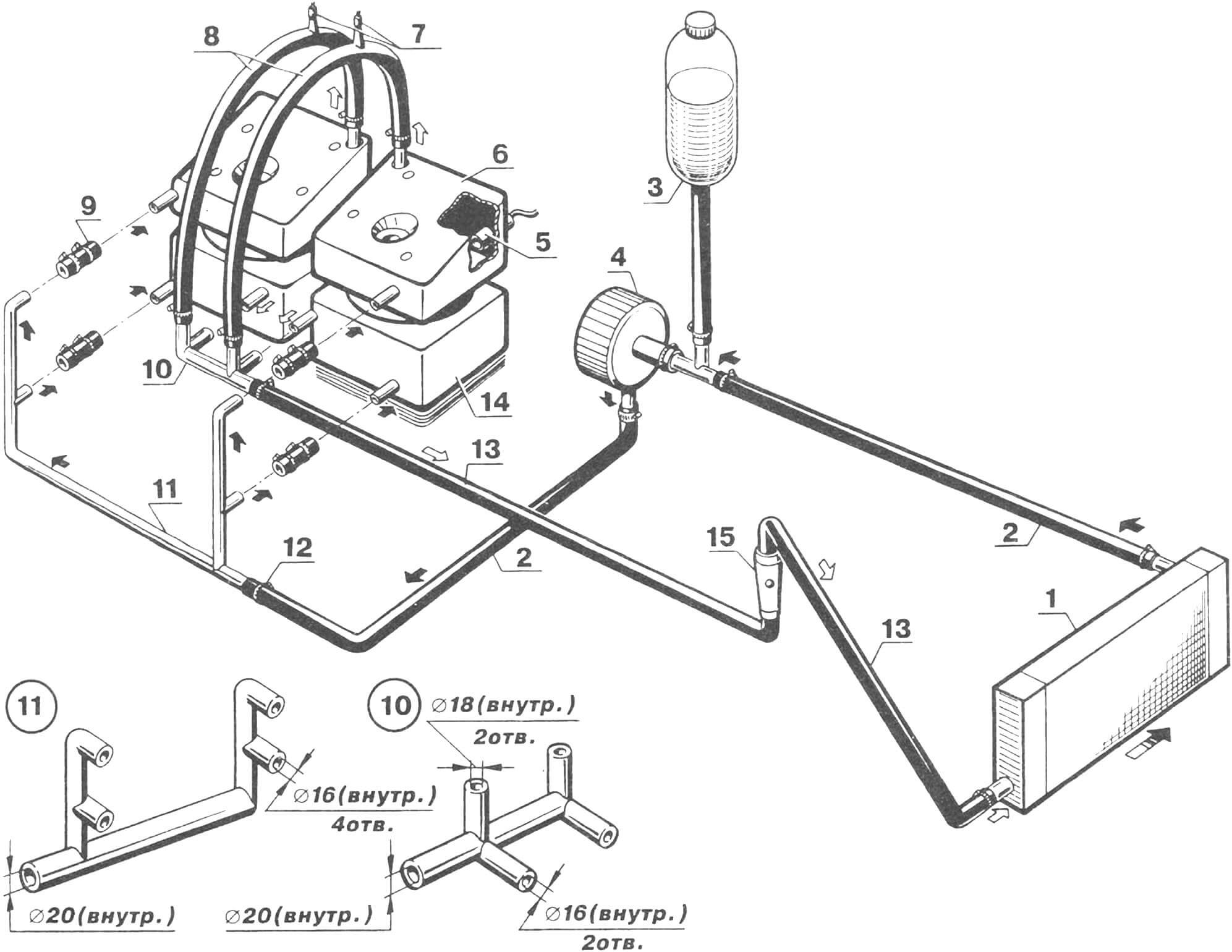
1 — radiator, 2 — polyethylene inlet hoses, 3 — expansion tank, 4 — pump, 5 — temperature sensor, 6 — “jacket” of the cylinder head, 7 — drain valves, 8, 13 — rubber outlet hoses, 9 — connecting pipes (6 pcs., two not shown), 10 — outlet manifold (steel), 11 — inlet manifold (steel), 12 — clamp, 14 — “jacket” of the cylinder, 15 — indicator of coolant circulation.
The modification of the cylinder head turned out to be somewhat more complicated. Its cooling fins were completely removed. In their place, a box made of 2mm-thick aluminum sheet — a “jacket” housing with inlet and outlet pipes — was installed. Holes for the mounting pins to attach to the cylinder were drilled, and aluminum bushings with stepped holes were welded into them.
The assembled cooling system operates as follows: the pump, connected to the fan shaft, pumps antifreeze (2.5 liters) into the “jackets” of the cylinder heads and cylinders. From there, the hot liquid goes to the radiator, placed in the nose fairing of the motorcycle and thoroughly ventilated by the incoming air flow. Cooled antifreeze is then directed back to the pump, and its excess goes to the expansion tank located above the engine.
The temperature and circulation of the cooling liquid are monitored using a temperature indicator and a simple indicator (made from a bottle neck, two brass meshes, and a ball) installed on the instrument panel.
1 — head housing, 2 — intake manifold, 3 — spark plug hole, 4 — “jacket” housing, 5 — exhaust manifold, 6 — bushing for mounting pin.
Modification, of course, led to the complication and increased weight of the “Beetle” power unit. However, in the end, it is all justified by the fact that the engine operates in an optimal thermal mode, and its increased power more than compensates for the weight of additional equipment.
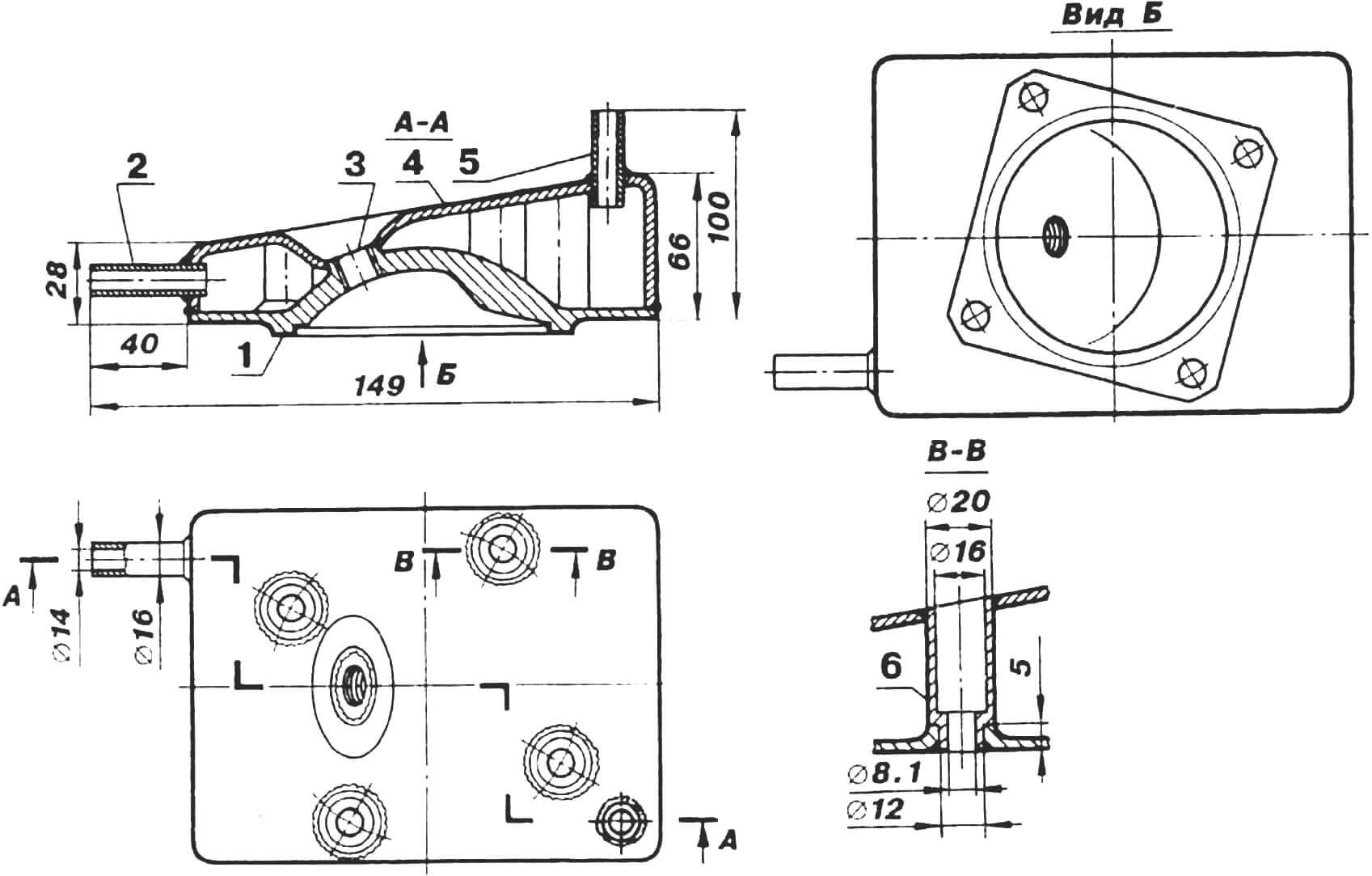
The engine is suspended to the frame, or more precisely to the shaped plate resting on support beams, by the same eight vertical studs that connect its heads, cylinders, and crankcase. Instead of the top nuts on the studs, long threaded sleeves are screwed in. The plate itself has eleven holes, eight of which correspond to the studs on the engine. Bolts are inserted through these holes into the threaded sleeves, securing the engine to the frame.
1 — housing (caprolactam), 2 — rubber tube, 3 — steel damping tube.
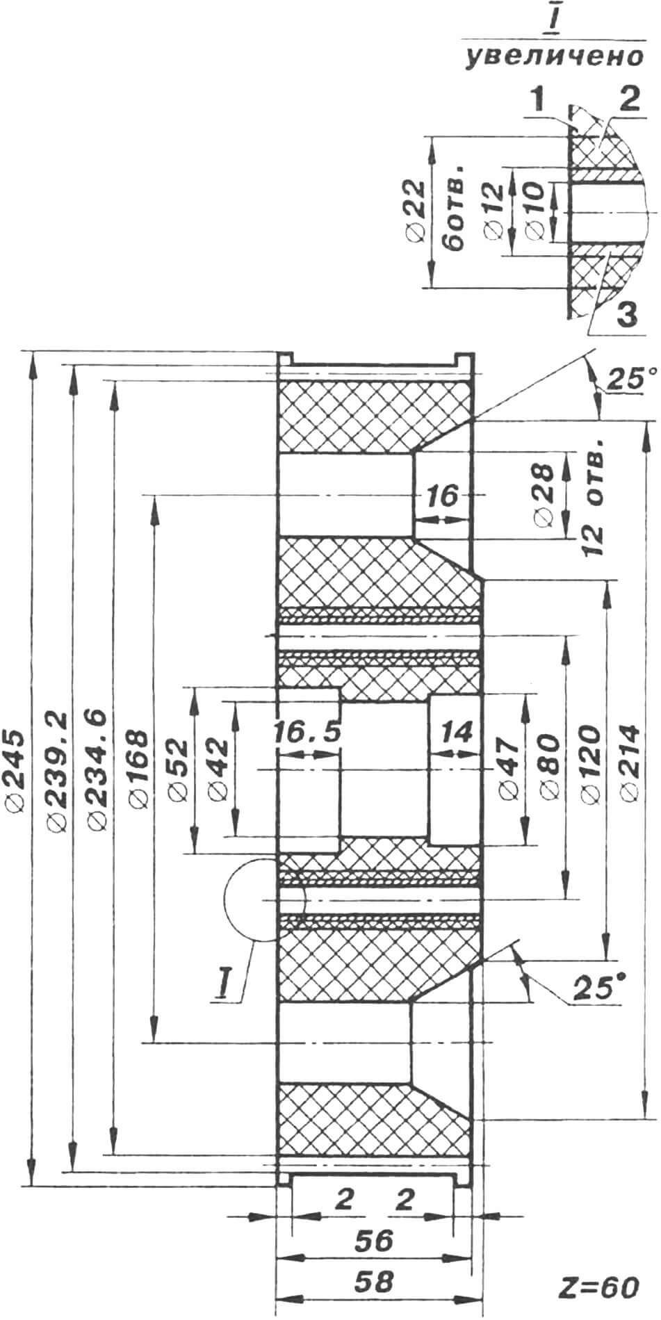
The gear ratio of the reducer is 1:2.2. Its driving gear is mounted on the tail of the crankshaft not directly, but through a spline bushing. Conversely, the driven gear rotates in bearings (No. 7205 and No. 204) mounted on a shaft securely fixed to the shaped plate with clamps. To prevent the belt from slipping, the rear ends of both gears are equipped with limiting cheeks made of duralumin.
In the development of the deltalete power unit, great attention was paid to the propeller. Air screws of various designs and made from different materials were tested. Preference was given to a lightweight and durable fiberglass propeller, allowing for adjusting the pitch of the blades and thus selecting the optimal engine operating mode for maximum thrust. However, this publication considers a wooden propeller as the simplest, most accessible, and cost-effective.
1 — technological hole (below — holes for cooling liquid), 2 — trimmed cooling fins, 3 — studs for attaching the resonator.
The propeller is connected to the driven gear with splined bolts through rubber damping bushings.
It is important to note that when the motorcycle is used as an aeromobile, aerosled, or aerocatamaran, a protective fence made of steel rods is installed around the propeller. In the case of a deltalete, it is removed to reduce the takeoff weight of the apparatus.
The engine’s fuel (a mixture of A-76 gasoline with oil) is stored in two aluminum tanks with a total capacity of 34 liters, installed behind the crew’s seats, and is supplied to the carburetors by the standard fuel pump.
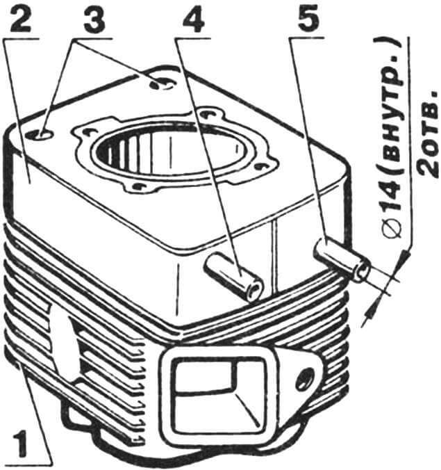
Front (in flight) cylinder with ‘shirt’:
1 — cylinder body, 2 — ‘shirt’ body, 3 — welded technological holes, 4 — exhaust pipe, 5 — intake pipe.
The engine is started with a special handle. It hangs above the pilot’s head on a cable that runs down to the standard starting device from the block on the upper pylon of the mast.
The pilot monitors the operation of the power unit, as mentioned earlier, using instruments on the nose fairing panel: tachometer, coolant temperature indicator, and indicator of its circulation in the cooling system. Engine control is done with an electric switch mounted on the longeron tube under the seat, and the throttle pedal under the right foot.
That’s about it. It remains to say that the realization of the age-old dream of human free flight is most palpable behind the wheel of a motodeltaplane. With the wheels off the ground, the feeling of the new and unknown rushes into consciousness along with the headwind. Rising higher, you notice that houses and cars become smaller, along with… our everyday problems. Absorbing otherworldly energy, you land refreshed, as if rejuvenated and, most importantly, confident.
Flight-Technical Data for Deltaplane “Beetle-42”:
- Capacity, persons: 2
- Flight range, km: 250
- Speed, km/h:
- Maximum: 90
- Cruising: 80
- Takeoff: 60
- Climb rate, m/s: 2
- Takeoff weight, kg: 370
- Deltaplane/Aerosled weight, kg: 165/115
- Fuel tank capacity, liters: 34
- Payload, kg: 170
- Engine: Upgraded RMZ-640
- Takeoff/run length, m: 50/30
- Speed in aerosled mode (max.), km/h: 80
A. Zhukov, A. Timchenko
Recommend to read
 “LATE TO THE TABLE”
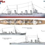
Ships built for combat — the approval that seems quite obvious. However, many warships of various classes and sizes and failed never "smell the gunpowder". Fortunately for mankind in the... THE DRAIN WIRE
In the country rain water falling from the height of the chute or breaks over time, blind area, or sprays from filled, but overflowing capacity which hurts the Foundation and walls. I'm...
