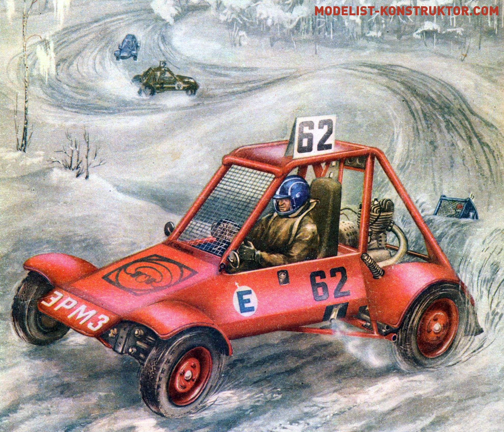
Every Sunday, the gates of the “Buggy-ERMZ” sports section open. Cross-country cars, or buggies, with the characteristic noise of motorcycle engines, emerge onto the factory yard. Today is a training day. On this day, the most enthusiasts gather, and everyone wants to test their skills before the upcoming competitions. After all, the one who shows the best result during training and has worked hard on creating and preparing the car for the competition will be the lucky driver. Most of the guys are between 16 and 20 years old, many of them have been interested in mechanics since the 3rd to 5th grade and possess enviable ingenuity. Sports activities are their favorite pastime for now. However, soon they will finish their studies, join the workforce, army units, and the technical knowledge, practical and sports skills, and training acquired in the sports section will undoubtedly come in handy in life. Experience shows that those who engaged in technical sports are usually proactive and hardworking in production; they are often referred to as “masters of all trades.”
Through our sports section, founded nine years ago by B.A. Okunem, the director of the Experimental Repair and Mechanical Plant (ERMZ), dozens of young people have passed. Two of them—Alexander Trofimov, a teacher at SGPТU № 173, and Yuri Suhodov, head of the garage at the “Fryazino” state farm—have organized sports sections in their teams and compete in races on cars made by their own hands.
For those who have decided to engage in the design and manufacturing of buggies and plan to actively participate in sports competitions, I would like to share the experience of our section, give a few pieces of advice on where to start, and suggest a simple design for a cross-country car for independent production.
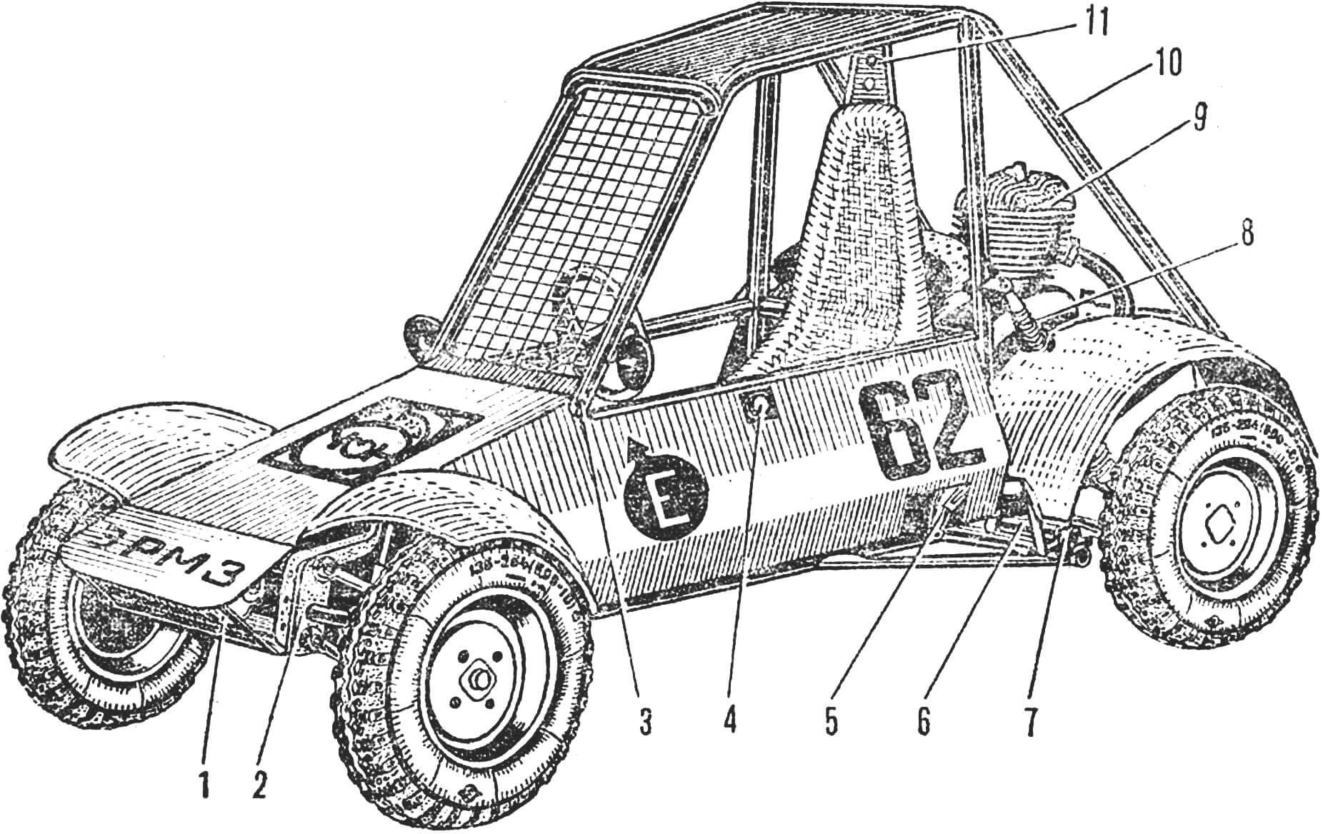
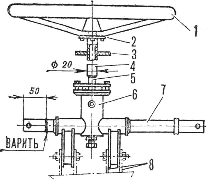
1 — fire extinguisher, 2 — front suspension, 3 — fire extinguisher activation, 4 — fuel tank neck, 5 — engine exhaust pipe, 6 — rear suspension lever, 7 — bracket, 8 — spring with telescopic shock absorber, 9 — engine, 10 — frame, 11 — headrest.
First of all, assess your capabilities correctly. In “big” motorsports, buggies with engines from serial passenger cars are most popular. According to the intraspecific classification, these are 7th-12th classes of special cross-country cars (SCA)—the official name for these vehicles. Their manufacture requires expensive units, sets of spare parts, and they usually face shortages. These resources are available to sports sections of large enterprises and car factories. It’s very challenging for a young section to compete with them.
It’s better if you start from scratch—zero-class buggies. When making mini-buggies, you will master work on various machines, acquire a range of useful skills. A beginner sportsman, aged 16, can start learning driving skills and participating in competitions on a buggy with a 350 cm³ engine.
Before starting to build a car, it is necessary to organize sessions in your section, and a section is, first of all, a team. It is difficult to work without the necessary equipment, materials, and parts, but it is simply impossible without comrades who are passionate about the same thing. It’s best if the section exists in the primary organization of DOSAAF, a sports and technical club, a youth technical creativity center, the House of Pioneers, or a young technicians’ station, where, as a rule, the leader is a qualified person interested in the cause. They will help organize the workshop correctly, find materials and parts for building cars, and clearly define the rights and responsibilities of everyone in making cars and participating in sports competitions.
The next very important question is the technical support of the section. Motorsports are among technically complex sports, so for independent manufacture of cars and keeping them in “shape,” a separate space is needed. It should be spacious enough to equip a workshop, store cars, materials, and parts. The workshop should be equipped with a locksmith’s workbench with a set of tools, a hand-held electric drill, table drilling and sharpening machines, a welding machine for arc welding, and a universal lathe.
Despite the maximum use of standard units and aggregates in the design, the frame of the car is homemade. The main load-bearing elements—safety arches and cross beams—are made from steel pipe Ø 35X2. According to the requirements of the DOSAAF Central Committee for cross-country cars, as outlined in the “Classification and Technical Requirements for Cars Participating in Competitions” (KiTT), it should be cold-drawn with a strength limit of at least 45 kg/mm². High-alloy steels like 30KhGSA possess such characteristics. However, due to difficulties associated with removing residual stresses in the welded joint, practitioners in building cross-country cars often use pipes made of ordinary structural steels with a slightly larger cross-section—Ø 38X2. Additionally, they are less scarce. For braces, struts, and non-load-bearing frame elements, pipes with a section of Ø 20X2
are used. About 10 meters of such pipes, cut into segments no shorter than 1 meter, will be needed for one car. Brackets, brackets, stiffening ribs, and connecting ears are cut from sheet steel with a thickness of 2-2.5 mm. The bottom of the car, driver compartment partitions, decorative panels, and wings are made from sheets of aluminum alloys like D16, AMg6, with a thickness of 0.6-1.2 mm. No more than four sheets measuring 1200X600 mm will be required for one car.
The proposed design for a zero-class buggy is entirely based on the components of a C3D minibike: an engine with a subframe, a main gearbox and half-shafts, front and rear suspensions, a steering mechanism, wheels, and a brake system. Only the rear suspension uses springs and shock absorbers from the “Vyatka” scooter.
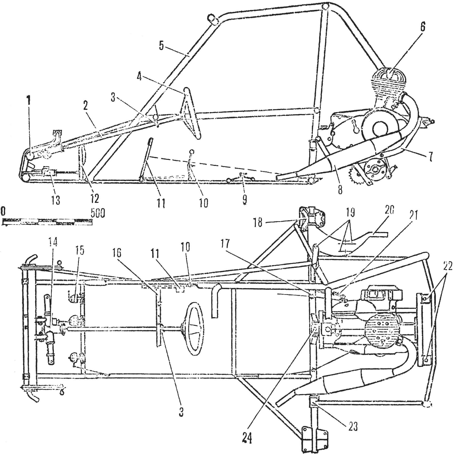
1 — front suspension, 2 — steering wheel shaft, 3 — steering shaft washer, 4 — steering wheel, 5 — frame, 6 — engine, 7 — subframe, 8 — exhaust pipe with silencer, 9 — reverse lever, 10 — gear shift lever, 11 — kick-starter pedal (dashed line indicates non-working position), 12 — brake pedal, 13 — main brake cylinder, 14 — steering mechanism, 15 — carburetor throttle control pedal, 16 — instrument panel, 17 — kick-starter cable roller. 18 — external hinge of rear suspension, 19 — shock absorber brackets, 20 — rear suspension lever, 21 — kick-starter lever / 22 — rear engine suspension brackets, 23 — internal hinge of rear suspension, 24 — front engine suspension bracket. (Some details and symmetrical elements of the structure are conventionally not shown.)
The main load-bearing element of the structure is the frame, welded from pipes. To assemble the frame and mount components on it, a stack must be prepared – a rectangular table with dimensions of 2000X600 mm, leg height – 1000 mm. Using paint or chalk, a drawing of the bottom frame is applied in actual size on its surface, outlining the contours of the mounted units and components. This method allows for the most rational placement of components, avoiding irreparable layout errors. Then, everything is laid out on the stack and connected with pipes. Brackets and attachment ears are welded to the frame, previously assembled with their own assembly. In this case, there is no need for careful marking of their position: it is enough to install the assembly itself in the chosen place, and then only “grab” the bracket to the frame with welding.
Arches of safety, two uprights, a crossbeam, and driver compartment separation tubes are made from pipes of larger cross-sections, Ø 35X2 or 38X2 mm. The remaining elements of the frame are made from pipes with a section of Ø 20X2 mm. Pipe joints are adjusted with a hacksaw and file.
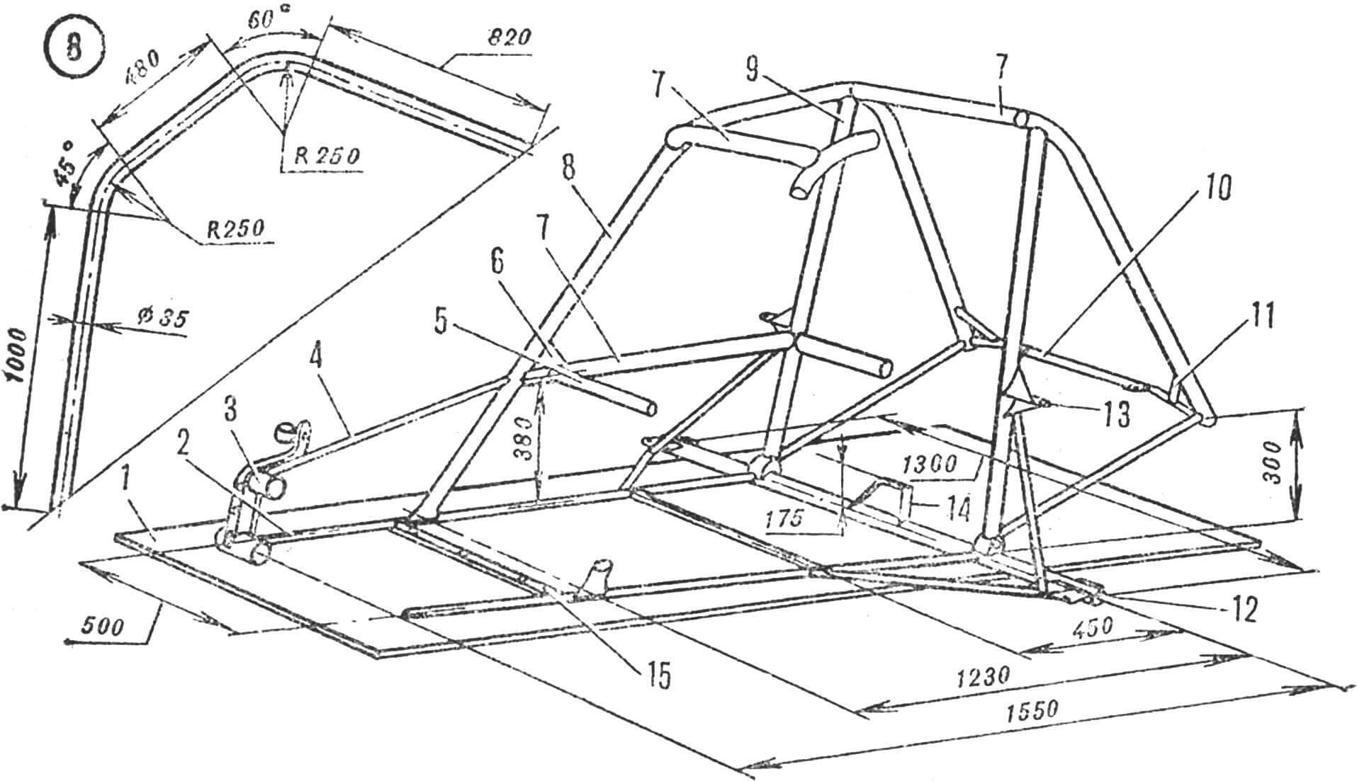
1 — stack, 2 — longitudinal beam, 3 — front suspension beam, 4 — strut, 5 — instrument panel cross-strut, 6 — brace, 7 — driver compartment side protection tubes, 8 — safety arch, 9 — upright, 10 — rear cross tube, 11 — brace, 12 — external hinge bracket of the rear suspension lever, 13 — upper shock absorber bracket, 14 — front power unit bracket, 15 — pedal crossbar.
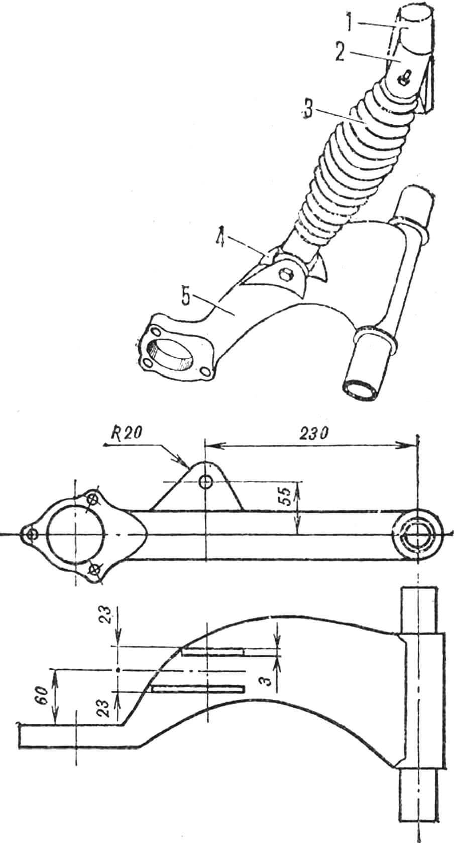
The front suspension assembly is welded to the frame’s longitudinal beams in such a way that it is tilted 12° backward from its previous position. This achieves a greater tilt of the kingpin, improving the car’s maneuverability due to the inclination of the wheels towards the center of the turn and the extension of the contact patch beyond the track. However, this slightly increases the effort on the steering wheel, but increases the clearance of the front suspension.
1 — steering wheel, 2 — flange, 3 — washer, 4 — steering shaft, 5 — drive gear shaft, 6 — steering mechanism housing, 7 — toothed rack, 8 — brackets for attachment to the front suspension beam.
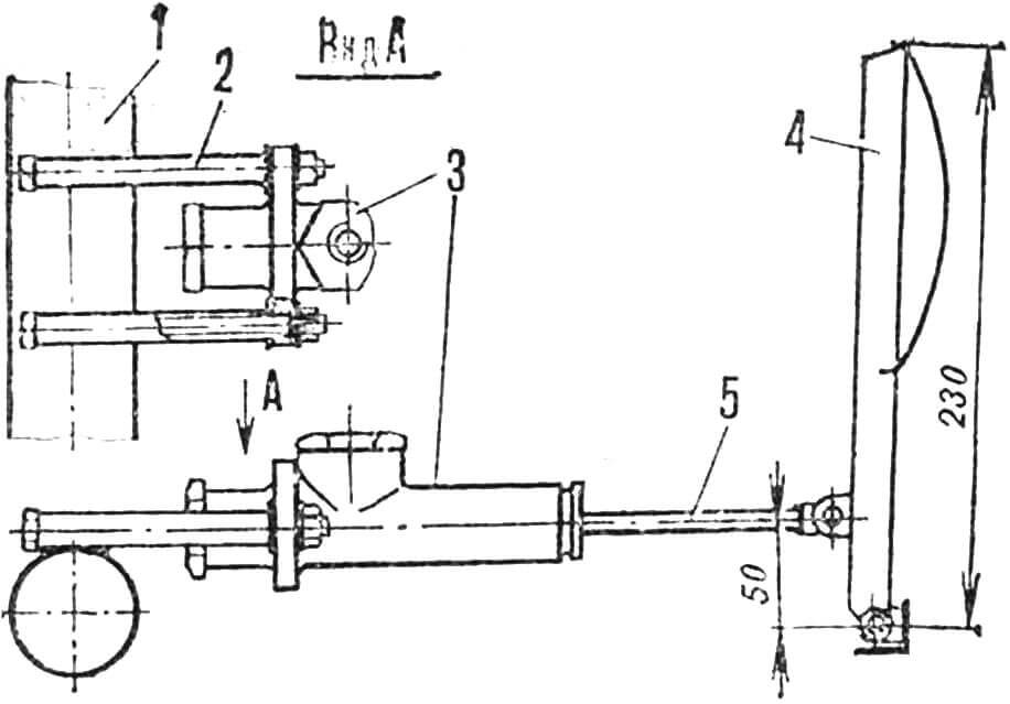
Minor changes have been made to the steering mechanism. Since it is installed in the plane of symmetry of the buggy, steering rods are connected to the toothed rack’s attachment ears from both sides. For this purpose, the attachment ear of the right rod is cut off and welded from the other side of the rack. The steering rods are shortened by cutting out their middle part so that after welding, the distance between the centers of the steering shafts is 400 mm, allowing for adjustment of their length in both directions. The steering wheel shaft is welded to the drive gear shaft of the rack mechanism. On the other end, a cut steel plate washer is placed, and then the flange for securing the steering wheel is welded. After attaching the fastening brackets to the mechanism housing, the entire assembly is mounted on the frame. Placing the steering wheel shaft, the position of the brackets of the rack mechanism housing on the upper tube of the front suspension is determined along the longitudinal axis of the car. The plate washer of the steering shaft, serving as its upper support, is welded to the middle of the instrument panel’s horizontal brace. Since the rack is helical, it is impossible to align its axis parallel to the transverse axis of the car, and although the slightly altered orientation of the mechanism will slightly disrupt the drive geometry, it will not have a noticeable effect on driving the car.
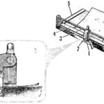
1 — frame strut, 2 — upper bracket, 3 — shock absorber with bracket assembly, 4 — lower bracket, 5 — rear suspension lever.
The rear suspension levers are installed on the cross tube of the frame through cylindrical hinges. Four brackets are used for this purpose, which are welded to the internal hinges (above the tube) and screwed to the external ones.
For their attachment at the ends of the cross tube, plate supports are made. Springs with shock absorbers are mounted on the car in the following way: The shock absorber is assembled with upper and lower brackets made from steel plates. The lower brackets are welded to the levers at a distance of 230 mm from the pivot axis. The rear suspension levers are lowered by 20° below the horizontal, and by extending the shock absorber rods to the maximum, the position of the upper brackets on the frame strut is determined. Since the loads here will be quite large, their upper brackets are reinforced with braces.
1 — lower tube of the front suspension beam, 2 — steel tube Ø 14X2, 3 — main brake cylinder, 4 — pedal, 5 — rod.
The subframe of the power unit is attached to the car at three points: on a high P-shaped bracket in the center of the cross tube and on two more brackets welded to the rear cross tube of the frame. For accurate installation, weld the front ones to the frame first, and screw the rear bracket blanks to the subframe. Securing the assembly in the front bracket and aligning it along the longitudinal axis of the car, determine the welding points for the rear brackets.
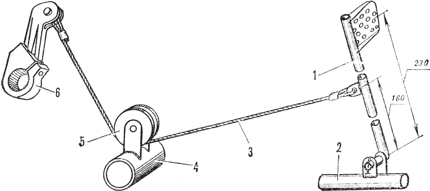
1 — kick-starter pedal, 2 — right longitudinal beam of the frame, 3 — cable Ø 3 mm, 4 — cross tube of the frame, 5 — roller, 6 — starter lever.
The rational placement of control elements is crucial for success in competitions. Only gear shift levers and reverse engagement levers with their tags are used from the minibike. Three homemade pedals with cable drives for the clutch and carburetor throttle are installed on the cross bracket of the driver’s compartment floor. The main brake cylinder is attached with horizontally welded tubes to the front axle tube, so the pedal acts on its piston directly through the rod. For starting the engine from the driver’s seat, a mechanical kick-starter with a cable drive from an additional pedal is installed. Its bracket is welded to the right longitudinal beam of the frame. Thanks to the foot start of the engine, the design of the car has become much simpler. Not only the starter but also the generator is removed from the engine. The necessary power for the ignition system, brake lights, and horn is provided by a small car battery. It is also assembled from an old car battery. To do this, three of the most capacious cells are determined with a load fork, and a lightweight battery for 6 V is made from them.
The seat is best made of fiberglass, but if that’s difficult, a seat from a minibike with a headrest will do for the initial stages, equipped with a vertical perforated metal sheet installed between the safety arches. The steering wheel is of reduced diameter, similar to those used in go-karts. Mandatory safety elements include seat belts and a fire extinguisher OU-5, mounted in the front of the car. The activation drive is brought to the front part of the left arch and marked with the letter “E”. This place should be accessible from both the outside and the inside.
After completing the assembly of the car, proceed to its debugging. The power of the standard engine is not high, but there are reserves for boosting. First of all, choose a reliable and well-adjusted carburetor, for example, the IKOV model from the “Jawa-350” motorcycle. Ensure the precise operation of the ignition system; replace the unreliable vacuum fuel pump with a diaphragm one with a mechanical drive.
It is difficult to list all the nuances of fine-tuning this complex unit. But if you decide to seriously engage in motorsport, you will always be helped with advice and consultation at the address: 107497, Moscow, Biryusinka Street, 7, section “BUGGY-ERMZ”.
B. TITOV
Recommend to read
 CUT… BEARING
Not find, perhaps, a car or complicated mechanism which isn't used ball bearings: they are embedded in devices and engines, airplanes, and tractors, bringing accuracy, reliability and...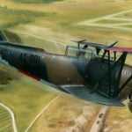 FRISKY “FI-FI”
Carrier-based fighter Grumman FF-1. Aircraft manufacturing firm Grumman Aircraft Engineering Corporation began work with the U.S. Navy in the late 1920-ies First, she collected the...
