 Because of the diversity of karts, built by athletes and produced by the domestic industry, the most advanced in design and for a number of technical characteristics is currently cards KS-76 designed in TSKTB DOSAAF of the USSR and manufactured by the Leningrad production Association “Patriot”.
This sporty machine has good stability, easy to operate. A good load distribution along the axes, a fit athlete and light weight undercarriage distinguish it from other known constructions weight Reduction achieved through the use of aluminum and titanium alloys and high-alloyed steels for the manufacture of individual units. Unfortunately, maps of KS-76 is available in limited quantities, mainly for the security of the USSR team. And since it is designed for the production in the factory, making it in the clubs forces athletes causes some difficulties.
Therefore, we offer a description of the device, the map built by the master of sports of Juvavum. Based on its design karts KS-73 KS-76 (with minor differences). Individual nodes in the process of construction has been somewhat simplified, but without any deterioration of the map compared to the base models. These simplifications will allow us to produce such machines in the workshops of the clubs and go-kart clubs with a minimum of required equipment (welding machine, lathe and milling machines).
Cards can be used for presentations in all of sports classes, in addition to “Pioneer” a description of the design which we have already given (see “M-To”, 1974, № 9, 10, 11).
Cards (Fig. 1) has dimensions 1020X1660 mm, 1060 mm base, ground clearance 40 mm Track front and rear wheels are made unequal: respectively, 770 and 875 mm.
The main elements of the frame map (Fig. 2) of seamless pipes brand 30KHGSA with outer Ø of 28 mm and a wall thickness of 1.5 mm. Additional items, which include front, rear and side bumpers, supports the steering column and supports the seat, made of pipes of the same brand, but Ø18 mm. they are All welded in place, as calculated under the growth of a certain athlete. No need for longitudinal adjustment of the seat position; to simplify the design, all the feet made stationary. They are located on the frame so that the seat is offset to the left of the longitudinal axis of symmetry of the map (in accordance with the weight applied by the engine and the driver’s mass).
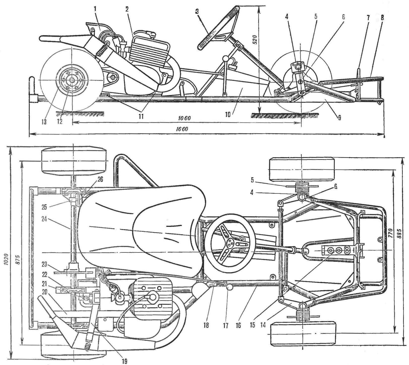
Fig. 1. The scheme map in two projections:
1 — seat, 2 — engine, 3 — wheel, 4 — drive mechanism brakes, 5 front brake disc, 6 — swivel front wheel, 7 — pedals 8 — cutting chipper, 9 — platform, 10 — tank, 11 — bracket-engine, 12 — hub of the rear wheel 13 drive wheel 14 is a rotating arm, 15 — brake master cylinder, 16 — tube frame, 17 — gear lever, 18 — drive rod gear shift 19 — bracket silencer, 20 — plate main gear, 21 — mechanism for adjusting the tension of the chain, 22 — bearing support rear axle, 23 — rear brake disc, 24 — rear axle.
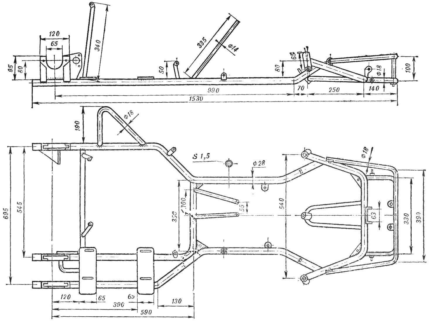
Fig. 2. Frame card.
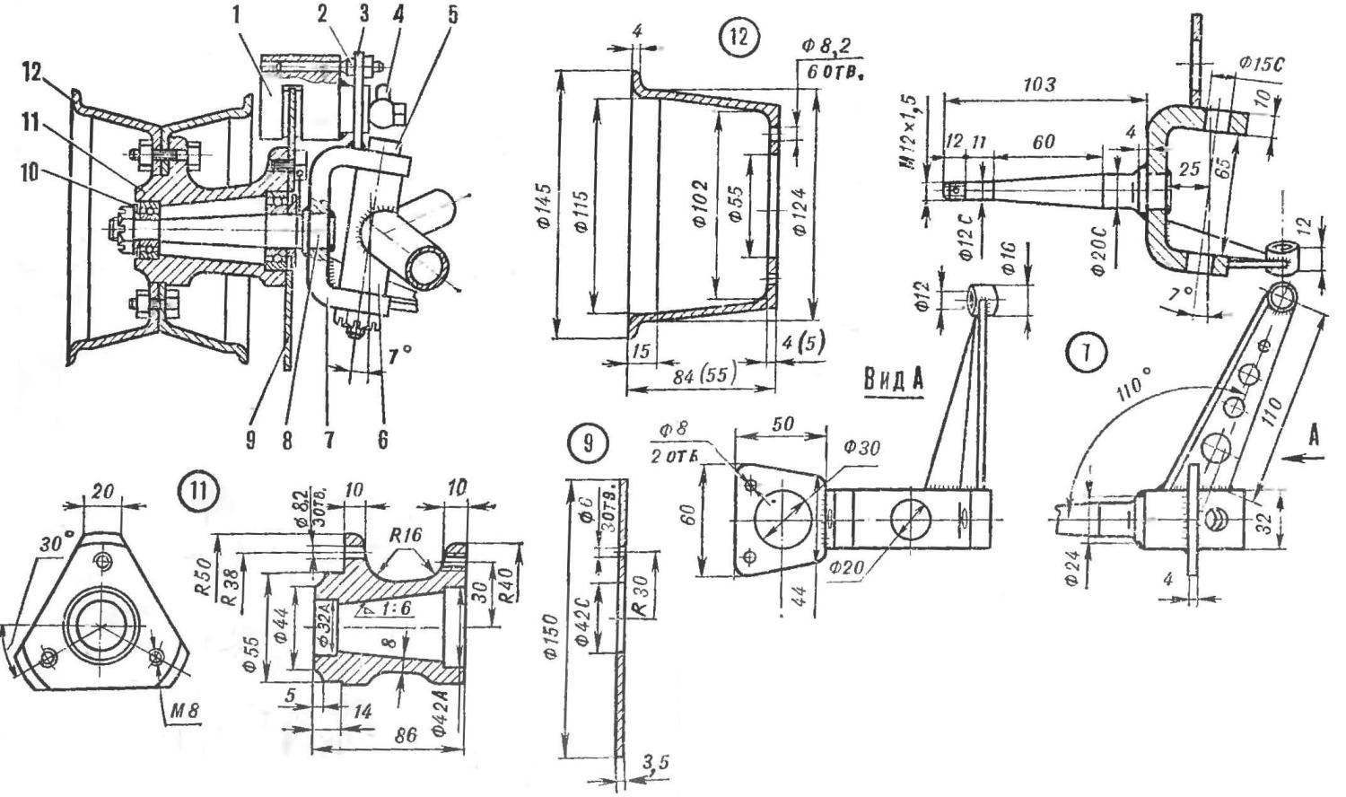
Fig. 3. Swivel peredney wheels:
1 — drive mechanism brake, 2 — pin, 3 — bearing mounting of the drive mechanism brakes, 4 — fitting line hydrocortison, 5 — pin, 6 — bushing for the pivot connection of the frame with swivel wheel, 7 — knuckle, 8 — axle front wheel, 9 — brake disc 10 — dust-proof washer, 11 — wheel hub, 12 — wheel drive.
To the frame at the same place welded on mounting brackets rear axle, made from sheet steel grade 20 (thickness 2 mm); plate engine mounts (steel 20, thickness 4 mm); bushings for pivot connection to the rotary nodes of the front wheels (tube with outer Ø25 mm and a wall thickness of 5 mm); the support of the fastening mechanism of the rear hydro-brakes; gusset plate for attaching the platform floor; the emphasis of the steering column; the axis of the accelerator and clutch and brake pedal bracket and master cylinder. Rear bump stop and the upper part of the front bumper is made removable. They are attached to the frame with bolts.
Eyes steering knuckle of the front wheels (Fig. 3) made of 45 steel on a milling machine. To ensure the reliability of steering knuckle axle the front wheels are pressed into the holes of the lugs and welded on both sides welding. Bushings for the kingpins are tilted in the transverse plane by 7°. The front camber is zero. In addition, the mounts have a tilt back in the longitudinal plane of 8°. To the top of the eyelets is welded a support for mounting drive mechanisms front disc hydrocortisol, and to the lower parts of swing arms steering. The levers are stops which limit the rotation of the front wheels (Fig. 3 not shown).
Hub front and rear wheels (see Fig. 3 and 4) of aluminum alloy D16T. Each hub connects to the wheels via three M8 bolts and nuts. To facilitate hubs in their mating planes sprezarkowni segments. In the front hubs contain bearings No. 201 and 104, closed dust-proof washers.
To the other of the mating plane of each front wheel hub is attached to the brake disc. Head bolts securing the disc scontrini binding wire of mild steel. Brake discs (Fig. 3, 4) — 3.5 mm; made of steel 45 and their working planes are ground.
Drives front and rear wheels are machined from aluminum alloy D16T.
The map applied to the discs of two sizes (the second in parentheses): little used in the front wheels; in the rear two discs, big and small. The width of the drive wheels is selected based on the application of the most affordable kart tire Voronezh tyre plant models-25A (at the front) and 28 (rear). This gives you the opportunity to operate them at reduced air pressure, which is known to positive effect on the stability map on the turns and provides better tyre grip. The design of the hub and drive allows to make fast change pre-inflated wheels. For this purpose, the discs have six holes: three bolts, they are connected in pairs to install on the hub.
Rear axle (Fig. 4) is provided with an open axle, three bearing supports, machined from aluminum alloy D16T. They feature double-row bearings No. 1204, closed dust-proof washers. At OSP made from steel 18ХНВЛ attached hub rear wheel, sprocket driven, the main transmission, rotor and fuel pump eccentric. The driven sprocket is connected with the axis of the collet Chuck. The clamping of the brake disc for weight reduction are made of D16T in the form of a tightening clamp.
Steering column from tube Ø 20 mm. In the lower part are welded to it a Pitman arm. The column rotates in two steel bushings: bottom welded to the frame, and the top with staples is secured by two bolts to the focusing column.
Fixing the steering column in the longitudinal direction is provided with two washers welded to it on both sides of the upper sleeve. On the upper end of the column by welding is attached to the washer, with which the three M6 bolts connected to the steering wheel is from aluminum pipe having three flat aluminum spokes with a thickness of 5 mm. the Wheel is lined with natural leather or covered by a thin porous rubber and plastic tape.
Length of the steering Pitman arm from the axis of the column to the axis of the mounting holes of the intermediate thrust equal to 60 mm. the Fry are pivotally connected to tie bar through the intermediate rod. In this design, choosing the length of the steering arm, it is possible to change the gear ratio of the steering — wheel without disrupting steering linkage. However, changing the length of the Pitman arm, it should be borne in mind that too short time will not provide a sufficient angle of the front wheels, and if too long will require considerable effort to turn the steering wheel.
In the steering linkage used rubber-metal joints (Fig. 5) in which work items are made from scraps of rubber hoses. These hinges are easier to work well when you change the angles in the joints and smooth out a few shocks from wheel to wheel.
Steering and intermediate pull — out thin-walled steel tubes Ø16 mm. in Order to change the length of the tie rod end (need it when adjusting toe), to the bracket of one of the hinges welded bolt M8X1. and in the end of the tie rod welded a nut with the same thread. Bracket of the second hinge is welded directly to the other end of the tie rod end. Steering and intermediate thrust at any position should not touch the frame and other parts of the map, otherwise they can bend.
The shift lever (see Fig. 1) is on the right. For its mounting on the right longeron has two eyelets. The lever is connected by a rod with a “flag” switch gear installed on the engine.
Seat “anatomical” made up of fiberglass with epoxy resin on plaster form, reinforced with wire. The form is produced by casting in a clay matrix. After curing, it is removed and thoroughly dried. Then the surface is cleaned a thin copper mesh, stained with nitro and after drying, lubricate with grease: the form is ready for pasting.
The fiberglass should be cut. Vileika seat is produced in one step, without long breaks. Epoxy resin into a clean dry ware thoroughly mixed with the hardener, which is added at the rate of 10% by weight of the resin. Thickly smeared glue pieces of fiberglass layers applied to the form, each time carefully pressing it across the surface. The total thickness of the seat should reach 4-5 mm. When Vileika necessary to ensure that between the layers are not left air bubbles.
A day ready seat removed from the form and trim the excess fabric. If the room is not good ventilation, then work with epoxy is necessary in the open air, and only in the dry and warm weather. All work necessary to perform in rubber gloves.
As a prototype, the seat is made deep to ensure a good fixation of the torso of the athlete in the bottom of the seat and the top.
Gas tank capacity of 3 litres is welded from sheet aluminum — for the relief of his weight. Tank is located on the platform beneath the steering column and fastened with a rubber harness. Tube intake of fuel welded to the lower part of the left wall of the tank and connected by rubber tube with pump. The tube tank has a tube of return of excess fuel and drain (atmospheric).
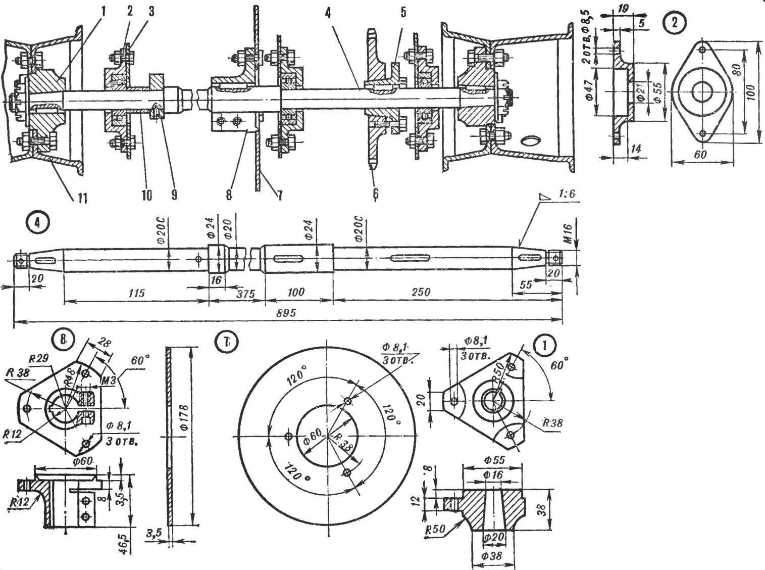
Fig. 4. Rear axle:
1 — wheel hub rear-wheel, 2 — axle support, 3 — mounting brackets rear axle, 4 — axle, 5 — cone collets, 6 — sprocket driven gear, 7 — brake disc 8 — node mounting of the brake disc, 9 — Cam fuel pump, 10 — spacer 11 — drives the wheels.
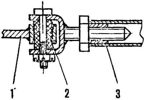
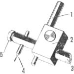
Fig. 5. The hinge of a steering trapeze:
1 — pivot arm, 2 — rubber sleeve-liner, 3 — transverse thrust.
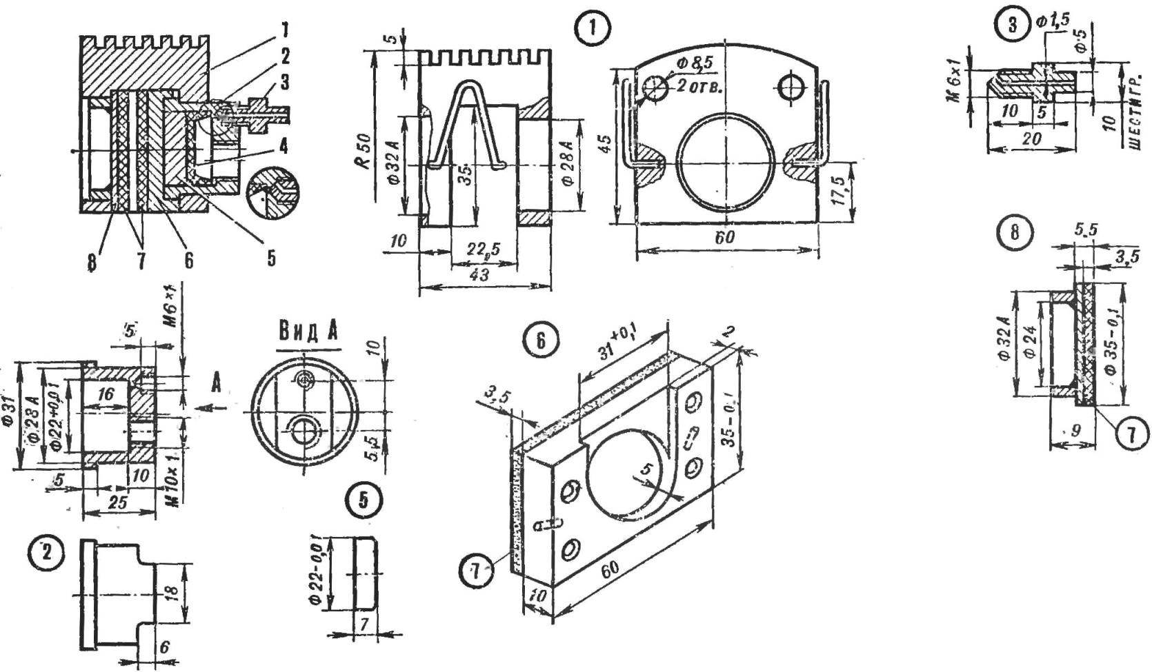
Fig. 6. Drive mechanism hydrocortisol:
1 — caliper 2 — working hydraulic cylinder, 3 — valve pumping brakes, 4 — rubber cuff, 5 — piston, 6 — movable brake Shoe, 7 is a friction lining 8, the fixed brake pad.
For pumping fuel from the tank to the carb used car fuel pump, which is driven from the eccentric of the rear axle. The pump is mounted on a bracket welded to the frame at the left bearing rear axle. The fuel is fed by an additional tank with a capacity of about 100 ml, mounted on the carburetor Reservoir is required for the uniform flow of fuel into the carb and to create a reserve of fuel when the pump is not working (at the start, with short stops on the track) when cornering on the fuel system is exposed to the centrifugal forces disturb the continuity of supply of fuel to the mixing chamber of the carburetor. If supplementary reservoir is full, excess fuel is returned from him back in the tank, contributing to intensive mixing of the fuel mixture. Additional tank carved from organic glass for easy control over its content; it has the shape of a cylinder 045 and a height of 80 mm.
Platform card from a sheet of aluminum with a thickness of 2 mm. In front of, next to the rotary wheel assemblies, it is wider and repeats the contour of the frame. The platform is bolted to the Gussets, are welded to the frame.
On the map disc brakes with hydraulic drive. They are absolutely not afraid of water, have less weight compared to the drum and fit well into the design of the card. And hydrosaline provides efficient braking with much less effort applied to the brake pedal.
The use of hydraulic drive also promotes the even distribution of braking forces on all wheels that improves the stability of the card. The brake system consists of master cylinder, highways, mechanisms, drive brakes with the working cylinders and brake discs. In our map the rear brake is common to both rear wheels. It used a disk of enlarged diameter. To improve the reliability of the brake actuator the brakes of front and rear wheels are made separate. This was made possible thanks to the use of the dual brake master cylinder from the car VAZ-2101. The main hydrocortisol made of metal tubes and flexible hoses used in the hydraulic system of the same vehicle (in Fig. 1, not shown).
The drive mechanism brakes, upgraded athlete by A. Kulygin, the simpler the base, has a robust system throughput and more efficient activity of the spring — conifers type. The device of the drive mechanism of the brake shown in figure 6. The caliper is milled from alloy D16T. It is inserted through the left (on drawing) hole and pressed into the right hole working cylinder, made of steel SH-15. In the end wall of hidrocilindru holes for the fitting of the inlet hose and faucet pumping the brakes. It is very important to taper the holes for the tap had the same angle as the taper on the end of the faucet.
The inner surface of cylinder is polished or processed by lapping the purity of the 9-10th grade. With the open side of the cylinder is fitted with solid rubber cuff Ø22 mm (from the braking system of the car “Moskvich”), and a piston, machined from aluminum alloy D16T. Precision manufacturing of the piston is controlled in the following lines. When the closed ports of the cylinder inserted into it dry the piston falls under its own weight just after the opening holes.
The movable brake pad (alloy D16T) with riveted thereto a pad of friction material is held by a cylindrical recess on the outer edge of the cylinder. In the absence of pressure in the braking system pad is pressed to the cylinder by two conifers springs, one ends of which are inserted into holes in her body and the other on the caliper. Springs made of wire (steel 65G) with a thickness of 1,5 mm and hardened. So they don’t fall out of the holes, their ends separated. In addition, to create a preload of springs in a free condition, the ends are separated by 4 mm when compared to the maximum distance between the holes for mounting them.
The stationary brake pad from the sheet of steel grade 45 with a thickness of 2 mm. For fixing the caliper to it of brass soldered steel ring, tightly included in the left (in the picture) the hole in the caliper. To Shoe riveted brake lining. The gap between the two pads must be larger than the thickness of the disc is 0.5 mm.
After Assembly the brake mechanism is set by the holes of the support on the two studs, screwed to a support of fastening of a brake. Because of this it is free centered for the drive that is necessary due to the gradual wear of the brake linings.
As reservoirs for brake fluid, as in the basic model, used transparent vinyl chloride pipe with an external Ø10—12 mm and a wall thickness of 1.5 mm, mounted on the steering column.
Collected on the map system hydrocortison need to pump the brake fluid in the same way as in a conventional car. Then you need to eliminate all, even the slightest leakage of the liquid, then check the operation of brakes “on the go”, paying particular attention to the uniformity of braking with all wheels on the efficiency of the brakes, fast and full release after releasing the pedal.
When the friction lining wear reaches a value at which the locked state, the gap between the movable pad and the caliper will be equal to 3 mm, the linings are required to replace or install additional padding.
Pedal map (see Fig. 1) made of tube has ø 14-ø mm, one end of which is bent at an angle of 90°. In addition to ease of fabrication, adequate stiffness and lightness, these pedals have other benefits: they provide the location of the control cable coming from the pedal, on the side of the Shoe of the driver.
Accelerator pedal p of the clutch is connected to the engine by flexible wires in the shell. The brake pedal its lower part acts directly on the rod of the brake master cylinder. All three pedals have the limiters reverse. In addition, to avoid damage to the carburetor throttle has a limiter forward stroke.
The main parts of the design are painted with synthetic enamel. Assembled the map need to adjust the ease of rotation of the wheels, the chain tension and length control cables. All threaded connections must be zaspirtovanny or locked double nuts.
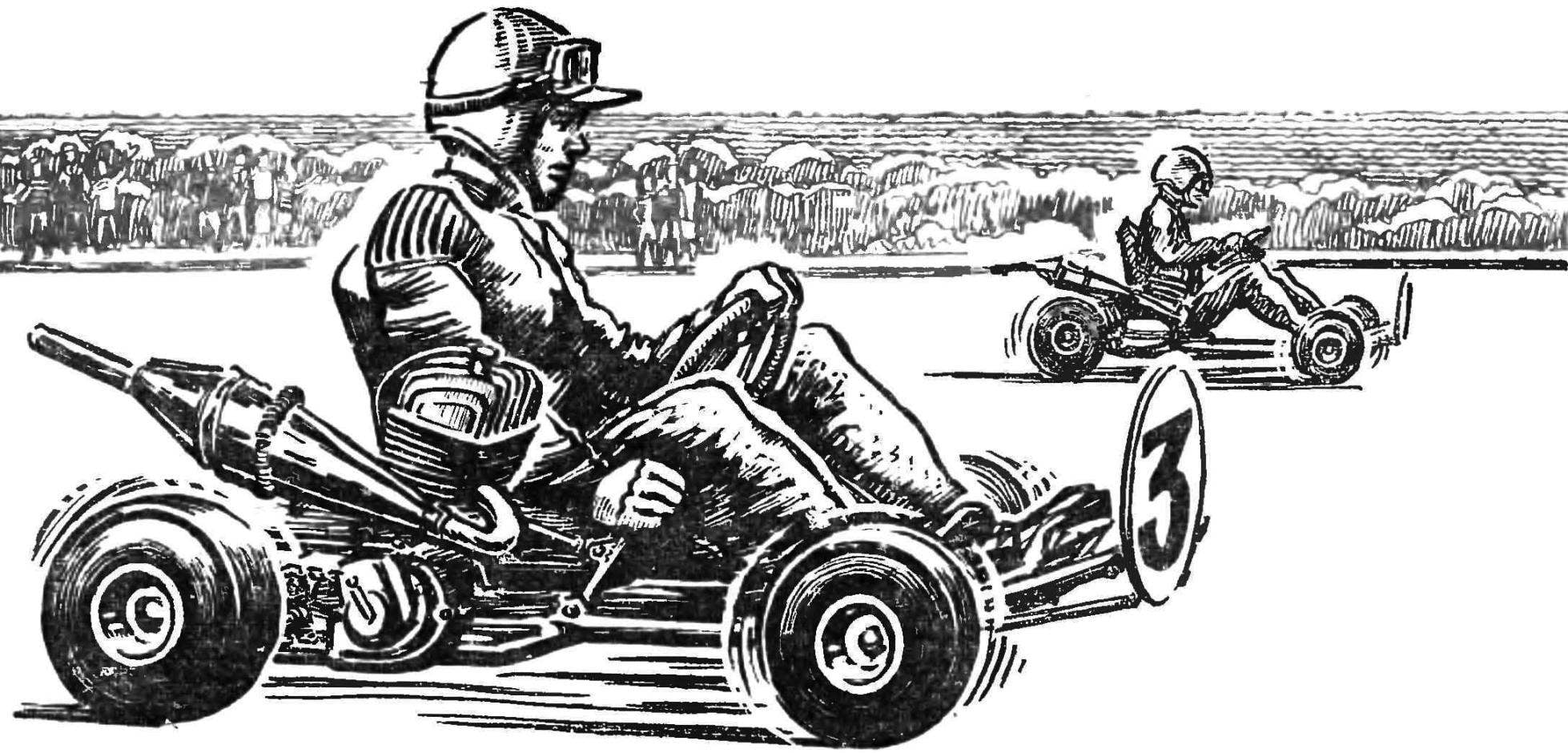
The word “kart” is now difficult to surprise someone. Competition PA maps — the smallest and simplest racing cars — has firmly taken its place in sports training of youth as first step on the path to great auto racing. Although these vehicles are relatively new, they already have a history, a chronicle of design exploration and technical perfection.
M. TODOROV
Recommend to read
 RUBBER CUTTER
No one is surprised that for drilling different holes require different tools. The bit set can not do, does not matter. The trouble is that the tool change takes a lot of precious... A LITTLE ABOUT THE SCALE
Recently an increased interest among readers judging by the letters and calls to the editor, raise questions related to the bench scale models. It is caused, apparently, the increasing...
