
 To radio sounded good on the UHF band, it should be adjusted to exactly take the radio. Will help you with this indicator fine adjustment circuit of which offers Bulgarian journal “Radio Television Electronics”.
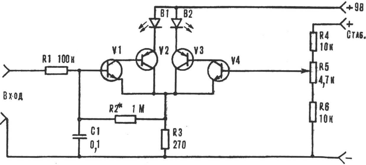
The DC component of the FM demodulator is supplied to the comparison circuit (comparator), is performed on four low-power silicon transistors! for example, KT315, KT361, and two LEDs АЛ102А—АЛ102В (see figure).
With the engine variable resistor R5 on the right shoulder of the comparator serves a reference voltage from a stabilized power supply.
Recommend to read
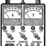 UNIVERSAL POWER SUPPLY
Every radio Amateur knows that without a source of constant and alternating stresses of different magnitudes in practical work is not enough. He needed to establish radiocontrole, repair...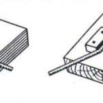 EXPRESS-TEMPLATE
Often a rigid wire or, conversely, a soft rod or a thin pipe required to give the necessary bending of a specific shape and size. Often try to do it in a Vice or just pliers that...
