 Improving the efficiency of the drive — a problem which concerned not only the designers of the bikes, but the owners of these cars. Since the invention of the Bicycle pedal drive brought, you might say, to perfection. To improve its efficiency without complicating the mechanism is hardly possible.
Sports and tourist bikes, for example, set the multi-stage transmission, but even in these actuators remains of the so-called “dead zone” when the cranks are near the vertical position. Pedal pass through this area of inertia, so as to create at this time, the full torque kicking very difficult.
The most straightforward solution seemed to use the elliptical drive sprocket. Since then many years have passed, but that is not visible to Bicycle manufacturers took advantage of this technical solution. Whether they have not yet comprehended the idea, whether they are stopped by technical difficulties.
I also have a solution to this problem. I changed not only the drive itself, only the plug at the rear wheels — built hinge-spring mechanism that performs the role of an accumulator of potential energy. Joint returns full force energy to the drive just in those moments when the rods are “dead zones”.
It offers readers tested in the technical solution to improve the efficiency of a pedal of a drive of a conventional road bike, on which I received the copyright certificate on the invention.
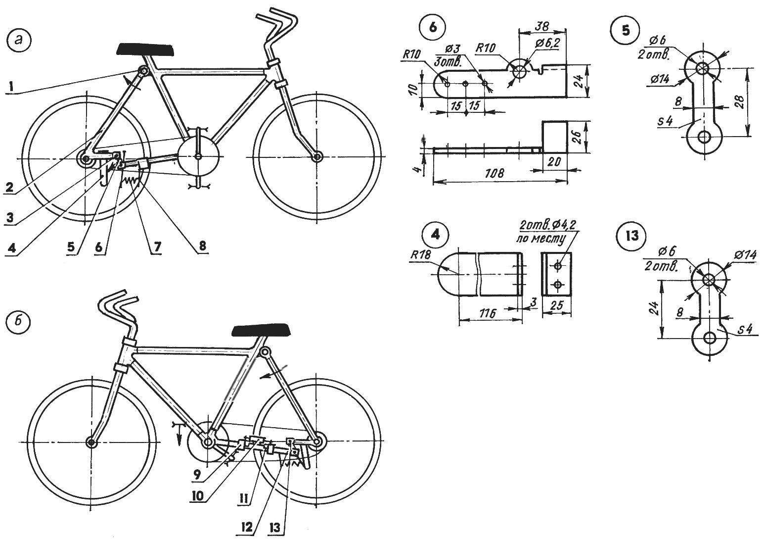
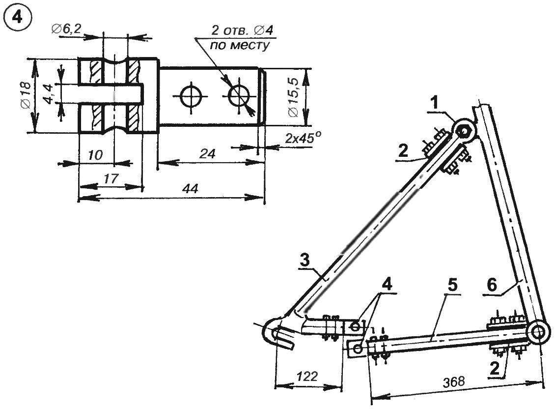
Double-joint mechanism (a position of the parts of the mechanism without load at the moment of passing foot cranks “dead zones”; — the position of the parts of the mechanism at the time of transfer of the maximum load (torque) drive:
1 — swivel seat forks with frame (stud M10 nuts); 2 — seat plug; 3 — tip double hinge (4 PCs); 4 — wire circuit; 5 — the right connecting rod; 6 — duplici lever; 7 — the spring (normally compressed); 8 console; 9 — yoke; 10 — limiting roller; 11 — mounting bracket to the axis of the roller; 12 chain plug; 13 — the left connecting rod
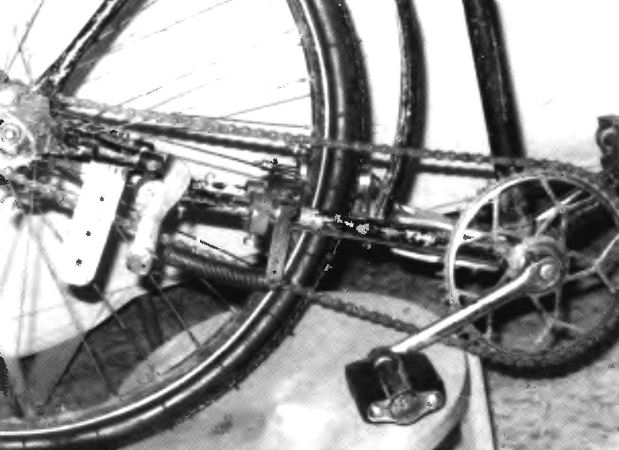
View of the double hinged mechanism on the right side. Here are mounted the guide chain, duplici lever with spring and the console.
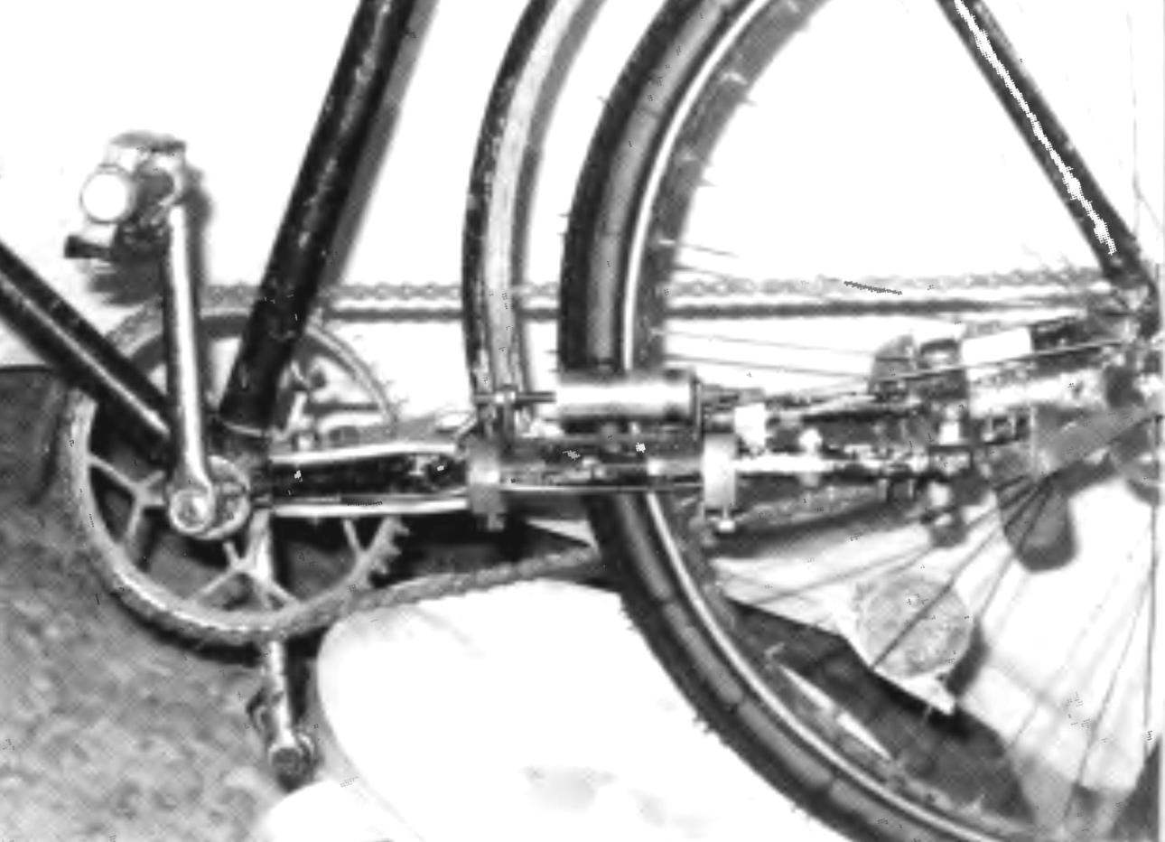
View of the double-joint mechanism on the left side. There is a restrictive video. Visible and lugs with connecting rod
First of all, changes in the design of the bike. They are that seatpost fork in the node it mounts to the frame (under the seat) now connects the hinge pin axis M8. Bikes old brands easy way to do this: the upper ends of the plugs in the seat node is attached to the frame by a bolt, which need only be replaced on the stud-axle. On newer models bikes welded on the top ends will have to cut off the frame tube and drill holes in them under the pin.
Feathers chain fork are cut approximately one quarter of its length from the axis of the wheel. The feathers at the incision site divorce — front folded down to distances equal to the dimensions between the holes in the connecting rod double-joint mechanism (Fig.1, det. 5,13).
At the site of incision in the tube plug is inserted into each pen for the steel NIB. Each of them is fixed in the pen with two M4 screws. In each pair of tips of a pen the M6 bolts fixed on the connecting rod is made of 4 mm steel sheet, and left the rod a little more right. This ensures a more uniform movement of the connecting rods at their work.
On the right side on the lower axis of the connecting rod is installed duplici lever tension spring with a force of 0.5 — 1 kg. Other end of the spring geared for the console, pulled the yoke to the front of the pen fork. To adjust the spring tension on the length of the lever arm and the console, drilled a few holes.
The scheme of alterations in the frame (seat and chain forks):
1 — swivel mount seatpost fork to the frame; 2 — strengthening indigenous ends of the forks; 3 — seat plug; 4 — terminals; 5 — plug chain; 6 — frame
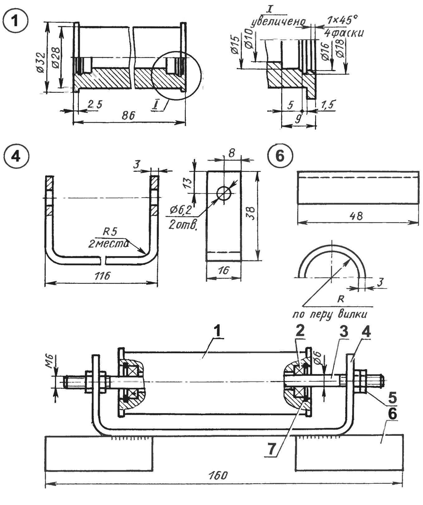
Restrictive roller:
1 — movie (St3, rod Ø32); 2 — bearing series 1000096 (2); 3 — axis (STZ, stud M6); 4 — bracket (St3 sheet s3); 5 — nut M6 (4 PCs); 6 — prop (St3, the sheet s4, 2); 7 — retaining ring (2 PCs.)
The device operates as follows. In motion when the pedal is pressed the upper portion of the chain not only rotates the sprocket of the leading rear wheels, but pulls the wheel itself, which moves slightly forward while turning the cranks of the device. The upper end of the right the connecting rod pushes the lever duplici that opposite end stretches the spring. When this occurs, a slight rise in the rear of the frame together with the saddle and the cyclist.
When the force is removed from the pedals (which occurs during their passage through the “dead zone”) is on the reverse of the connecting rod mechanism and wheels under the pressure of the mass of the cyclist and the compression of the spring. The slack chain is selected, an asterisk with a leading wheel continues rotation and the connecting rods are of the “dead zone.” For one full turn of the rod there are two such cycles.
Since, during the progress rear wheel forward of the lower portion of the chain is slightly slack, then here would need the length compensation circuit. But he inevitably would complicate the mechanism design and required replacement foot brake on a manual. In order for the chain with the sprocket wheel when not slack off on the back right of the pen forks I installed the guide of the chain and fastened it with the same two bolts that mounted here the tip.
And again. When transferring a significant torque to the drive itself tries to turn the drive wheel clockwise (since the drive is on the right side). With a significant backlash in the hinge-spring mechanism (which is inevitably in its manufacture at home) the actuator it works, and the tire of the wheel begins to touch the left feather. To avoid this, a restrictive video.

Bike after the upgrade
The roller is mounted on an axis on two bearings series 1000096, although it would be better to set the bearings 80000 180000 or with shields or seals, but I was not. The roller is movable along the axis limits, which allows you to move the rear wheel hinge. The axis of the roller — stud M6 are installed in the bracket that is welded to the two pillars and secured to the right pen stationary part of the chain forks with clamps and screws. The clamps I picked up ready, but you can do it yourself — the same as install plumbing to water pipes when you need to fix the leak without welding
And the last one. Because of the design of the seat and chain forks have evolved and have been weakened, their root ends (the abutting frame) reinforced plates of duralumin sheet thickness of 5 mm, with rubber, pinch each pair of plates with two bolts M8.
Special measures to increase the efficiency of the drive frame with a built in hinged spring mechanism I did not make, but the sensations suggest that the work of the cyclist easier half. Riding on this bike even on a dirt road and rugged terrain is a pleasure.
S. RESHETOV, Kazan
Recommend to read
 GAZEBO IN THE GARDEN
In a quiet corner of the garden of his manor house planted Douglas fir. Three years have passed. The tree grew, grew. And then came the idea to build a small gazebo that over time, the... FROM FLASHLIGHT INTO A FLOAT
Many are addicted to fishing for them this activity is a fascinating vacation. The very same UDA, rod, adise is one of the oldest fishing gear; by definition of V. I. dal's dictionary,...
