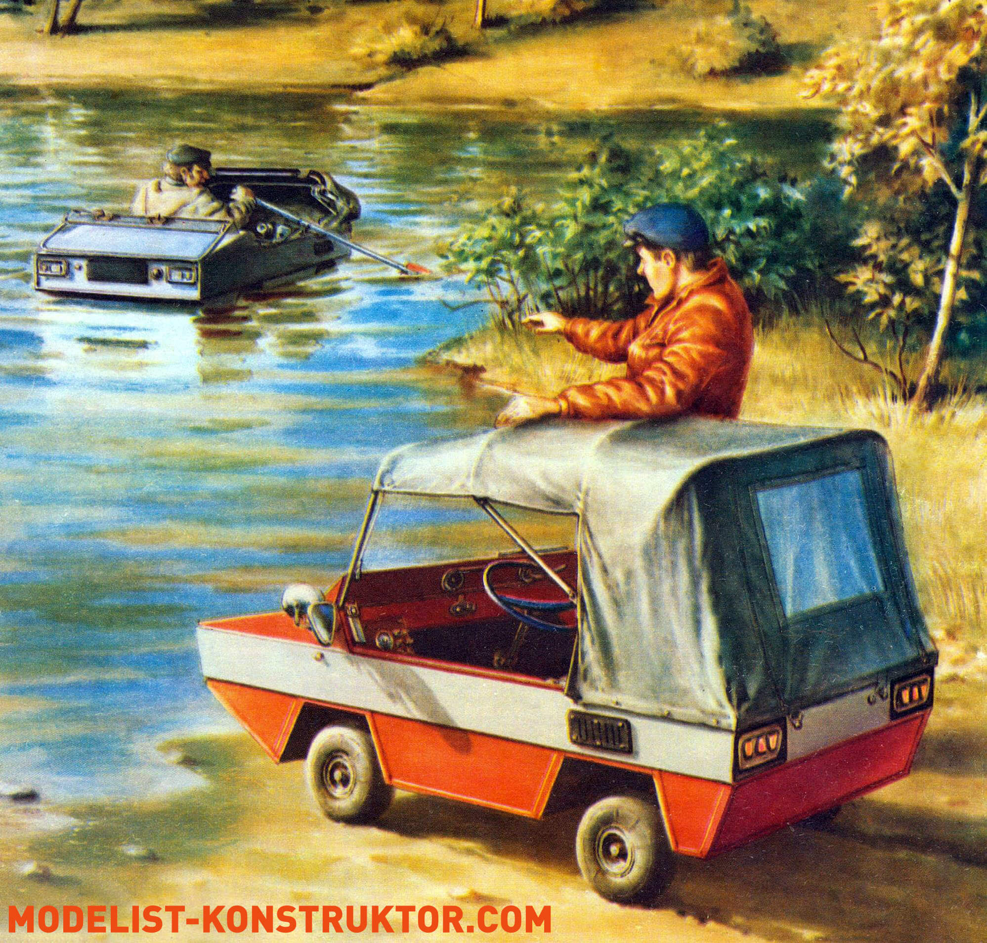
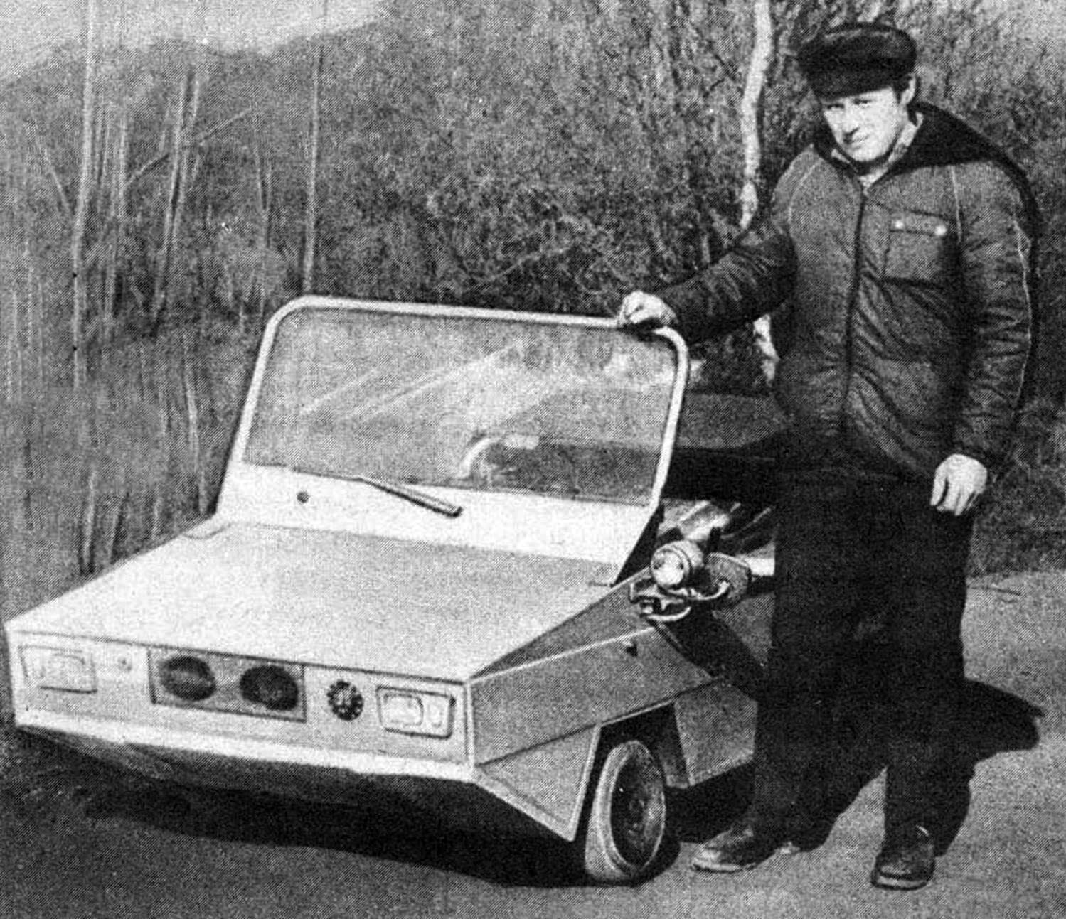
FLOATING CAR with an engine from a moped was successfully built by A. Nazarov from Yaroslavl. I want to introduce readers of “M-K” to the assembled amphibian. I designed it to practically solve a whole range of problems and contradictions that arise during the design process. There were quite a few of them, but the main ones are worth mentioning.
1. Is it possible to create a car with a 50 cm3 engine? What will be its speed and load capacity?
It turned out – yes! With a weight of 80 kg, it easily carries an adult at a speed of 30–35 km/h (on asphalt), provided that the car has a resilient wheel suspension. It is much more difficult to control with a rigid suspension – the car bounces and does not respond to the steering wheel, which becomes apparent at speeds over 20 km/h. But at a speed slightly above bicycle speed (16…18 km/h), it easily carries two adults and climbs any hills on highways. With a single driver, it can climb a ramp with a 15° incline from a standstill.
2. Is it worth tuning the engine?
It turned out – not worth it. When tuning the engine, the power increase comes from increasing the RPM. The torque does not increase. The engine characteristic becomes torque-dropping. All this complicates starting from a standstill and requires the use of a multi-speed gearbox. Interestingly, the Sh-51 and D-6 engines, working with the same gearbox, behaved the same, despite different power outputs.
3. What can be the minimum dimensions of a single-seat amphibian? What speed is possible?
I can report that I assembled my car in an ordinary apartment on the tenth floor. Therefore, its dimensions were limited by the dimensions of the freight elevator and the box serving as a garage for the amphibian – 2000X2000X700 mm. Thus, the height of the side is 300 mm, allowing the amphibian to stay afloat with two adults, dipping into the water to a depth just above half of the side. And with a single driver, the draft is only 120 mm. On the water, the car is very stable – you can throw a fishing rod, sit on the hood, side, or stern without the risk of overturning. The low placement of the engine and chassis, which became a kind of ballast, played a role here. I believe that the minimum possible dimensions for a single-seat version can be reduced to 2000X800X400 mm.
The speed of movement on water with such dimensions, non-retractable “landing gear,” and “box” type contours according to the laws of hydrodynamics cannot exceed 3 km/h. I confirmed this by achieving a speed with a stationary waterjet – 1 km/h (the low efficiency of the transmission and the waterjet itself played a role); the speed on oars and with the “Sputnik” outboard motor (2.5 km/h) turned out to be the same. Therefore, I had to abandon both the waterjet and the outboard motor in favor of oars. Later, I installed off-road aluminum-shelf treads on the wheels – I managed to reach a speed of… 0.5 km/h. It was convenient to control due to the tilt – for spinning, it suited me quite well.
I want to warn everyone who plans to build an amphibian: if the car is not designed for planing, then its speed on water depends only on the dimensions of the hull – the longer and taller it is, the higher the speed, the wider and shorter it is, the lower the speed. The economical power required to move such vehicles on water is usually 1/3 to 1/5 of the power required for land movement. Hence the simple conclusion – build an amphibian according to traditional car standards, but ensure the watertightness of the hull and provide a water propulsion system. The application area of such vehicles is mainly on land. In the water, they are rarely used and cover short distances. This technique is mainly needed by fishermen and sometimes tourists. If you want a fast amphibian on both water and land, build a boat and put it on wheels – there is no other way out.
4. What can be the off-road capability and fuel consumption?
I note that fuel consumption due to a decrease in speed and an increase in weight has doubled (compared to the “moped” one) and reached 4 liters/100 km. It should be noted that most homemade vehicles assembled on the basis of motorcycle engines are not champions of fuel efficiency and consume up to 10 liters of mixture per hundred kilometers! And if we consider that the engine, working with overload, loses power after 15,000 km, then the dream of every self-made vehicle enthusiast of daily trips on such a car, for example, to work, seems like a clear utopia. Getting around by public transport in the city is faster and cheaper.
Regarding the off-road capability of the amphibian, it is almost the same as that of a moped. The latter, however, performs much better on sand. It turned out that small-diameter aircraft tires with a round tread are far from the best propulsion: they “cut” into the track on loose soil, skid, and the car eventually “sits” on the bottom. Even off-road treads did not help in this case. In principle, it seems that the off-road capability of homemade “amphibious” vehicles should be the same as that of regular cars; a single rear-wheel-drive axle with a clearance equal to the wheel radius is quite suitable for them. The point is that even army amphibious vehicles sometimes cannot get ashore without winching.
5. What additional equipment is required for the amphibian?
My small experience has shown: first and foremost, water drainage means are essential. Without them, the car quickly becomes a kind of submarine. Water can enter the hull through loose seams, seals, and other connections during rain, an unsuccessful descent into the water, or encountering a good wave. It is necessary to ensure that the water entering the hull flows to a specific location determined by the differential and tilt, without being delayed by partitions and bulkheads. This will make it easier to remove water. The simplest way to do this is with any bucket or scoop, but you can also provide a manual or electric pump or an ejector (if a waterjet is used).
Second, something that is absolutely necessary – a winch of any design. I became convinced of this after the first “swim,” pulling the car out of the pond. With its weight of only 80 kg, I managed this task with great difficulty. The simplest (but also the most inconvenient) is a wheel winch. Following it in terms of simplicity and availability is a manual hoist: with its help, you can pull the car out from anywhere. And the most difficult is to make a winch with a drive from the transmission. However, in my case, the latter option turned out to be the simplest. To check the winch’s functionality, I threw an anchor on the gate beam and, making sure it was securely hooked, engaged the clutch – after a few seconds, I found myself in the air with the car. It is thanks to the winch that my amphibian can get out on the most inaccessible and inconvenient shore. A 2-meter-high gap, without a splash and even a sandbar at its base, is not an obstacle for it.
Next, something else that is also important – ensuring unsinkability or simplifying rescue operations after flooding. All floating cars, even military ones, filled with water, sink. The point is that it is simply impossible to place floatation blocks in the hull: they will fill its entire internal volume. There is only one option – to provide the driver and passengers with life jackets, allowing them to quickly leave the car, and also to provide buoys: rising, they will lift the ropes behind them, which can be used to pull the “drowned” vehicle.
It is also useful to provide a protective fender in the body structure, protecting it from all sides from damage, dents, and scratches during mooring to other floating vehicles. For this purpose, it is also useful to think about the location of headlights, taillights, and rear marker lights, as piers and gangways during floating parking in rough seas can cause a broken headlight or torn-off marker lights.
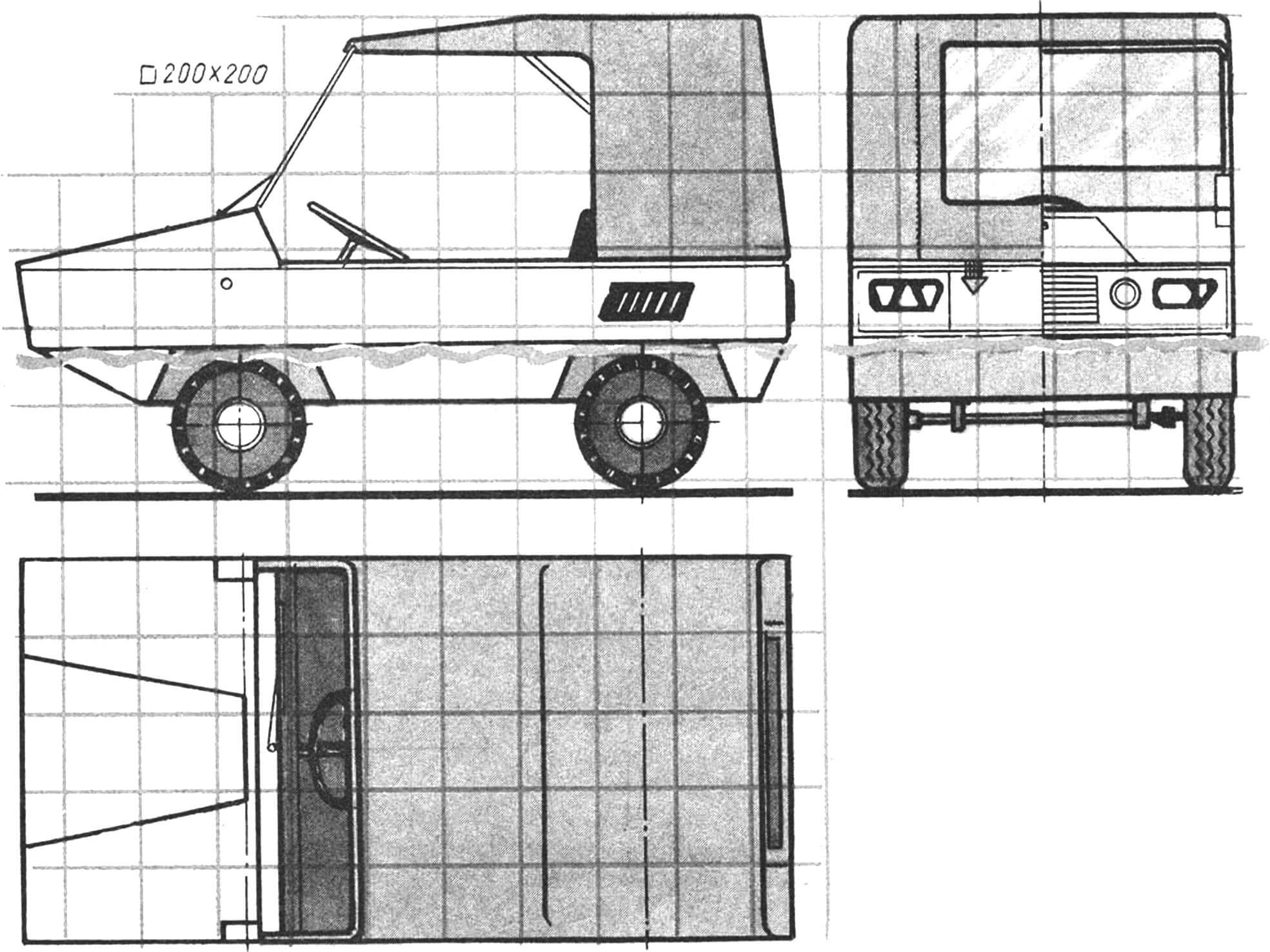
My amphibian was built as a kind of model, or, more precisely, a laboratory on wheels, so there are many simplifications in it. In particular, I did not hope to achieve high speed, so I abandoned the front and rear axle suspensions. The body of the car is load-bearing, assembled using “boat” technology. The only difference is that it has two keel beams, and the stringers are inclined – it turned out to be easier to attach wheel wells. Stringers No. 1 and No. 2 converge in a triangle and have a common beam, serving as the instrument panel. Stringers No. 0 and No. 5 are sheathed: they serve as transoms. The rear transom is reinforced and has a pad for attaching an outboard motor. The body is sheathed with pressed cardboard (hardboard), and the wheel wells are made of roofing iron. Assembly was carried out without a slipway, all body parts were connected with nails and nitro putty used as glue. The finished body was putty and painted with oil paint.
Front and rear axles are almost the same as those of a sports kart but without brakes. The reason is that brake pads swell and wear out quickly when in contact with water. Both axles are externally attached to the keel beams of the hull with bolts. The steering is also “kart-like”; the trapeze is located outside the hull, it has two rods connected to the yoke on the steering shaft. The sealed steering shaft is like a dagger on a sailboat: a tube with a flange and support attached to the bottom, serving as a “well,” and the steering shaft rotates inside it. Its upper part, together with the steering wheel, is detachable so as not to interfere with rowing and is fastened with a bicycle “Kama” clamp.
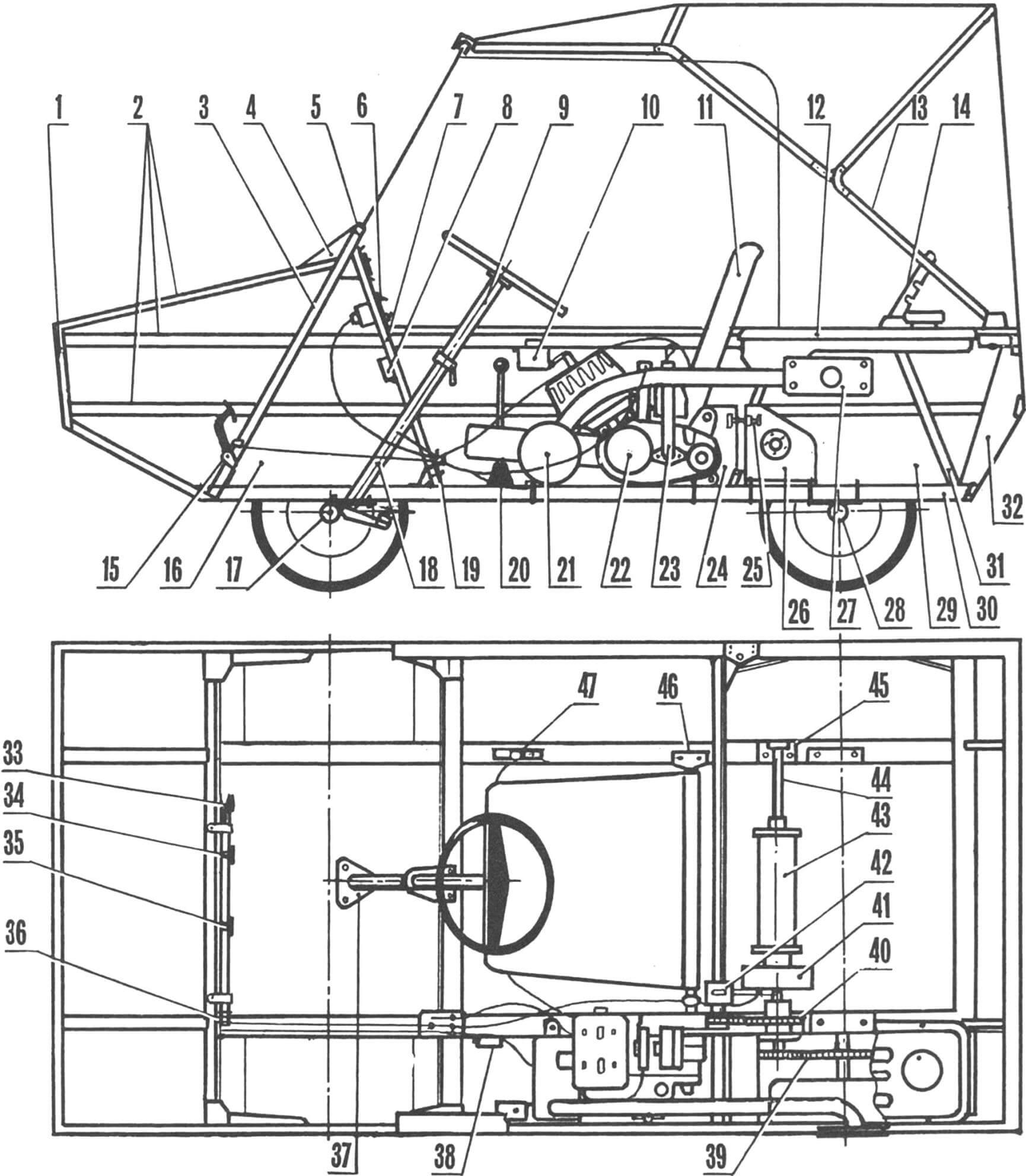
1 — front transom, 2 — stringers, 3 — stringer No. 1,4 — windshield hinge, 5 — windshield frame, 6 — instrument panel, 7 — stringer No. 2, 8 — turn signal relay, 9 — removable part of the steering column, 10 — ignition coil, 11 — seat, 12 — fuel tank, 13 — hinge frame of the awning, 14 — awning frame lock, 15 — pedal unit, 16 — front wheel well, 17 — front axle, 18 — steering shaft well, 19 — overall tension device of pedal cables, 20 — gear shift lever, 21 — muffler, 22 — engine Sh-58, 23 — oil level indicator, 24 — movable plate for engine mounting, 25 — chain tension device, 26 — transmission shaft mounting plate, 27 — flange for fixing the exhaust pipe, 28 — rear axle, 29 — rear wheel well, 30 — keel beam, 31 — stringer No. 4, 32 — rear transom, 33 — gas pedal, 34 — brake pedal, 35 — clutch pedal, 36 — control cable fastening, 37 — steering shaft well flange, 38 — stop signal switch, 39 — transmission from the transmission shaft to the drive axle, 40 — chain drive from the engine to the transmission shaft, 41 — brake drum, 42 — holder and brake shoe shield, 43 — winch coil, 44 — transmission shaft, 45 — bearing housing, 46 — brackets for attaching the seat to the keel beam, 47 — gear shift lever.
The rear axle does not have a differential, both wheels are driving, which increases off-road capability and has little effect on maneuverability – the car, like a kart, turns almost on the spot. The torque on the axle is transmitted by a chain; to ensure its tension, the axle can move towards the stern. The axle rotates in two bearings, the housings of which are bolted to the keel beams.
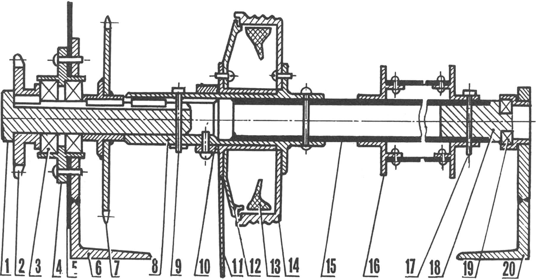
1 — spline pin, 2 — sprocket (transmission from the transmission shaft to the drive), 3 — bearings with double-sided seal (from the water pump of the “Moskvich-412”), 4 — bearing unit housing, 5 — wheel well wall, 6 — left support of the transmission shaft — attached to the keel beam, 7 — driven sprocket (transmission from the engine to the transmission shaft), 8 — transmission shaft housing, 9 — pin-locator of the spline pin, 10 — stop ring, 11 — brake shoe shield actuator, 12 — brake shoe shield, 13 — brake shoes, 14 — brake drum, 15 — extension of the transmission shaft, 16 — self-pulling winch drum, 17 — pin-locator of the self-pulling winch drum, 18 — plug of the transmission shaft, 19 — support bearing, 20 — right support of the transmission shaft (attached to the keel beam).
The transmission or intermediate shaft receives torque from the engine through a chain drive, the driven sprocket of which can be easily replaced. The number of teeth is chosen from 13 to 25 depending on the load and road conditions. Then the torque is transmitted either to the winch coil, freely mounted on the intermediate shaft and having a removable pin for fixation, or through a seal and chain drive to the rear axle. On this intermediate shaft, there is also a brake drum that operates on the rear axle and winch.
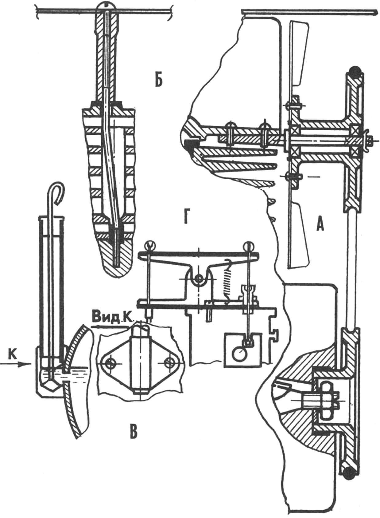
A — installation of forced cooling, B — turning the cylinder head by 90°, C — installation of the oil level indicator dipstick, D — throttle return booster.
The engine is attached to the left keel beam and is moved for chain tension along with the muffler and base. In the engine crankcase Sh-58, instead of a kickstarter shaft, a pedal shaft from the engine Sh-51 is mounted. The left connecting rod is cut off near the wedge, and a pipe is welded to the right. Thus, the kickstarter for the engine is on the right and easily starts with the left hand. The engine is converted to forced cooling. For this, it was necessary to rotate the cylinder head by 90°. Since the position of the pins did not allow doing this, I drilled holes in the cylinder jacket to Ø12 mm and bent the pins to align with the holes in the head at its new location. The head nuts should be extended, and a deflector should be attached to them with screws. The cooling fan is connected to the engine crankshaft by a belt drive and rotates on an axis attached between the cylinder head and the cylinder with two screws. The pulley is attached to the crankshaft with a hollow bolt screwed into the threaded hole in the flywheel. The drive pulley is a sealing rubber ring from the sleeves of the engine YAMZ-236. Engine control is little different from the scheme adopted for the “Pioneer” kart.
The seat and awning frame are made from folding bed parts. The awning can be rolled up from three sides, and the openings are fastened with “zippers.” The windshield can be folded down onto the hood when needed.
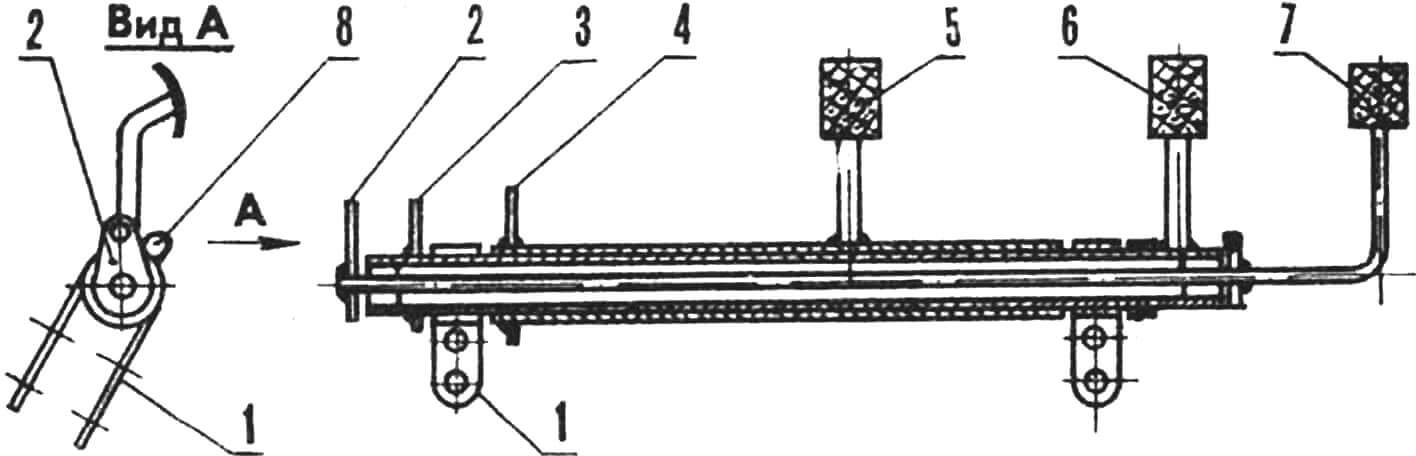
1 — clamp for attaching the pedal shaft to stringer No. 1, 2 — gas pedal cable, 3 — brake pedal cable, 4 — clutch pedal cable, 5 — clutch pedal, 6 — brake pedal, 7 — gas pedal, 8 — cable tensioner (welded to the left clamp).
The car is equipped with front and rear turn signals, brake lights, and clearance lights. All lighting devices, including low beam headlights and a searchlight, are taken from bicycles and mopeds. A sound signal is also provided.
The amphibian turned out to be quite reliable and convenient. During the season, it covered about 2,000 km on the roads and rivers of the Yaroslavl region. There were no breakdowns. However, there were difficulties with the very capricious engine.
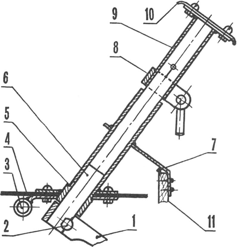
1 — steering yoke, 2 — wedge for attaching the yoke, 3 — front axle beam, 4 — bottom, 5 — steering column well with flange attached to the bottom, 6 — steering yoke shaft, 7—additional support of the well, 8 — clamp for the extension, 9 — removable extension of the steering column, 10 — crossbar of the steering wheel, 11 — stringer No. 2.
Wherever the car ended up, it caused sincere delight, surprise, and, I won’t hide it, envy. I had “troubles” with traffic police officers who often stopped me – usually out of curiosity. After all, a vehicle with an engine displacement of less than 50 cm³ and a speed below 40 km/h is considered a moped or a motorized bicycle according to the rules, and therefore it is not subject to registration, and you can ride it without a driver’s license.
Unfortunately, the amphibian lasted only one season. Created as an experimental platform, it was still a convenient and reliable means of transportation, and most importantly, it infected me with a passion for further creativity. Now I have set myself a new task – to make a new amphibian based on it, but already a two-seater and with a more powerful engine. Calculations and drawings are halfway done. I would like to correspond with other DIY enthusiasts engaged in similar work. Knowing the experience of colleagues in this hobby makes it easier to continue the work.
My address: 150052, Yaroslavl, Dzerzhinsky Avenue, 29/71, apartment 62.
TECHNICAL CHARACTERISTICS OF THE AMPHIBIAN
Number of seats – 1
Vehicle weight, kg – 80
Gross vehicle weight, kg – 200
Overall dimensions, mm:
length – 2000
width – 1000
height – 1200
Wheelbase, mm – 1050
Ground clearance with wheels, mm – 300
Speed on land, km/h – 30
Speed on water, km/h – 3
Fuel consumption, l/100 km – 4
Winch force, kgf – 250
Maximum angle of ascent from a standstill – 20°
Engine – Sh-58
Power, hp – 2
Cooling – air
A. Natarov, amateur designer
Recommend to read
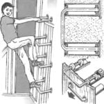 DISAPPEARING STAIRS
In the wall of the corridor built-in Cabinet or pantry can be equipped with a pull-out-push-step from metal pipes. They will not interfere with and, if necessary, easily POPs out,... SPEED FOR WINTER RACING
The model with the air screw 2.5 cm grade3 designed and manufactured in a self-similar circle of Penza city station of young technicians. It is inherent excellent ride quality, stability...
