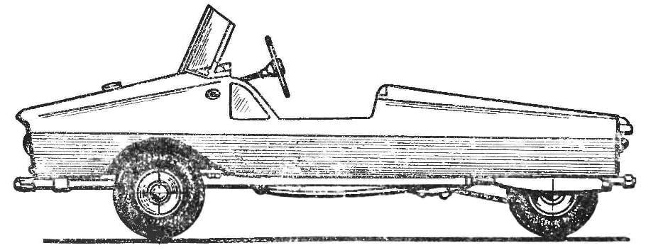
 (The end. Beginning at No. 10, 1973) In the tenth issue of the magazine, readers got acquainted with the General layout of the three-wheeled micro-car, only “Friendship” design Bykovskiy, G. Malinowski and B. Horev. Today we talk about refinement and alterations to the factory components and parts that have been applied in the construction of this interesting machine. Remember that to make their own does not make sense. Even with the appropriate machining equipment it will greatly increase the cost and complicate the work, not to mention the fact that the quality of parts made in primitive conditions, much lower than factory.
FRONT AXLE
To improve the resilience and reliability suspension front axle motorized С3А mounted on the micro-car, only “Friendship”, subject to alterations: a hydraulic damper has been replaced and pendants from a motorcycle “Pannonian-250”. To do this, steel 10 or 20 new carved fingers and the linking sleeve (Fig. 2). Especially carefully it is necessary to perform the threaded part of the fingers, the radii of curvature and the groove of the thread outlet, in that place are breaks too sharply undercut shoulder.
Pendants are attached to the fingers of the castellated nuts using standard bushings and carefully splinted.
Practice has shown that it is possible with identical success to use as an old (unregulated) and new (variable stiffness) of the suspension of the “Pannonia”. You can use charms from other motorcycles, such as “IZH-56”, length regulate it inserts or threaded bushings. Limiter release is the belt made from durable doubled fabric.
For mounting the front bumper and fascia brackets must be welded (or to put on bolts) two scarves from steel sheet of thickness 3 mm., Their shape and size depend on the layout of the front of the machine, so the drawing of the gusset plate shown schematically. Brackets, or gussets, also welded angle brackets for mounting is the front flaps of the wings.
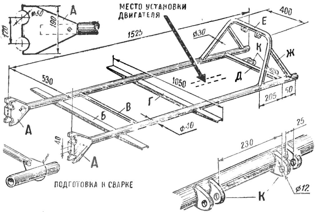
Fig. 1. Frame Assembly and details:
A — Shoe mounts of the front axle; B, the first cross beam; the axis of the levers of the manual starter and switch gear; G — second transverse beam; D, the third transverse beam; E — P shaped arc shock mount suspension, the struts arc; K — lugs mounting swinging (pendulum) plug the rear wheels.
Installation of brake drums on the hubs of the front wheels, as shown by the sea trials of our first car, absolutely necessary: a single rear brake does not provide effective braking. The drums are fastened by five bolts to discs, and brake pads with a shield to the hub in the tides which is necessary to drill holes and make cuts under 6-mm screws.
Drums can be machined on a lathe of appropriate size aluminum or steel blanks or made from mild steel with thickness 2-2,5 mm method of rolling (extruding) on a special mandrel and on the lathe. In aluminum case you need to extrude the cage of steel, which will “trigger” the brake pads.
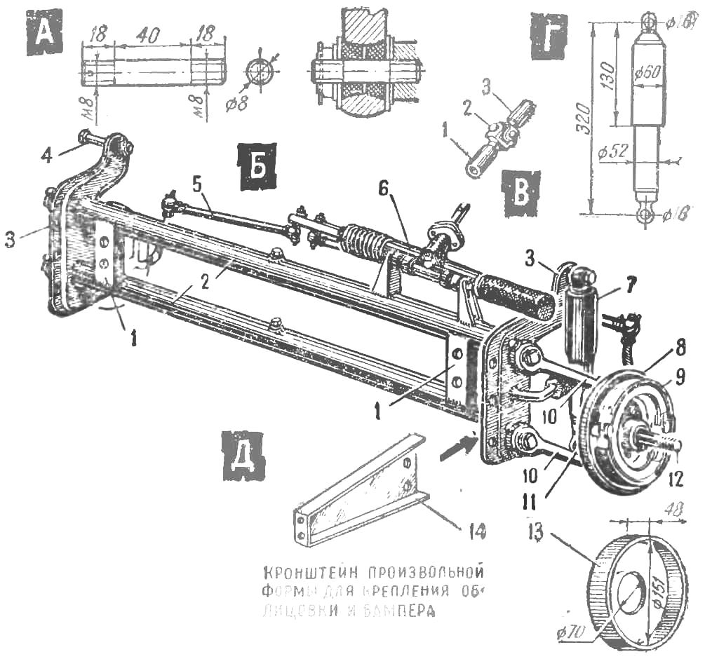
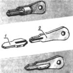
Fig. 2. Front axle and details:
A — finger of the shock absorber “Pannonia”; B — axle Assembly: 1 — front fixing to the Shoe frame; 2 — cross-beam; 3 — the connecting brackets; 4 — the finger of the shock absorber; 5 — tie-rod; 6 — rack and pinion; 7-attenuator; 8 — reference disc brake pad; 9 — brake pads; 10 — swinging lever; 11 — the place of fastening of the shock absorber; 12 — shaft; 13 — brake drum; 14 — an arm; In — cross gimbal steering shaft: 1 — tube bottom; 2 — hinge Hooke; 3 — a tube top; G — suspension “Pannonia”, the principal dimensions.
Brake system — supporting disks, pads, Cams and levers — taken from scooter “T-200”. But this is not the only solution. Also known system with hydraulic drive and brake drums from a variety of motorcycles, trucks and cars. You can finally, without any alterations of the hub and rim to make a complete modern disc brakes like a car “Zhiguli”.
All alterations suffered by front axle, do not pose a big difficulty and can be done in any school workshop, where there is a lathe height of centres not less than 150 mm.
The next node, which we redid, the connection of the cushion rack and pinion steering gear with the steering shaft. As you know, microcar С3А this is accomplished the simplest way is the cross pin. In such a context, to change the steering wheel position the height is impossible. We used the prop spider from the axle shaft motorized С3А old issue that had led to a significant change in the tilt steering shaft and therefore the position of the steering wheel. It is necessary to obtain the low driver position.
FRAME
The overall layout of the micro-car, only “Friendship” provided by flat tubular frame (Fig. 1), which consists of two longitudinal members and three cross members. The longitudinal elements of the frame have front shoes And for fastening the front axle and rear sloping arch E, which is pivotally mounted the pendulum fork and the shock absorbers “Pannonia”. If possible, the frame should be welded from thin-walled steel pipes in accordance with the drawing.
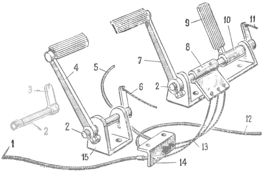
Fig. 3. Block design of the pedals:
1 — flexible sheath cable actuated brakes the left front wheel; 2 — cushion pedals, and a 3 — foot with a hole for cable terminal; 4 clutch pedal; 5 — flexible sheath cable actuated brakes the right front wheel; 6 — cable of the cutoffs of coupling; 7 — a brake pedal; 8 — the carriage of a brake pedal; 9 — the gas pedal; 10 — clutch pedal; 11 — the rope of gas; 12 — flexible sheath cable actuated brakes the drive wheel; 13 — cables brakes; 14 — adjusting strut attachment fittings; 15 — stand pedal.
In order to avoid distortions and warpage, welding must be conducted on a special fixture (the stocks) of thick boards. Will be welding parts are carefully adjusted to each other and temporarily shrink mild steel wire, as shown in figure 1. Technology and sequence of welding is as follows: first, the use of cross ties “tack”, and then straightening and welding the tight continuous weld. Thus obtaining a rigid base frame, can be welded to it shoes fastening front axle and arc for a pendulum suspension forks drive wheel.
We applied the pendulum fork taken from scooter “Tula 200” first releases. You can apply and circular plug from the machine “Tula Tourist” — this will create added convenience when changing wheels.
BODY
The frame of the car body of the open type shown in our drawings, is welded from thin-walled steel tubes with a diameter of 12 mm, which requires about 15 meters. To the frame with M3 bolts fastened sheathing of plywood with a thickness of 3 mm, to be pasted on top of one layer of fiberglass or cotton calico.
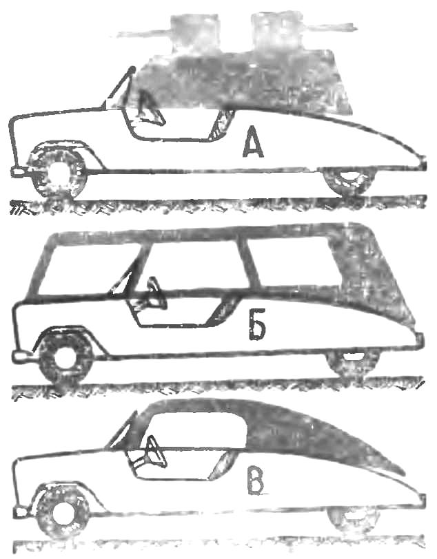
Fig. 4. Different types of bodies:
A — “armored”; B — body “wagon” type; body type “sports coupe”.
If the required number of tubes does not appear, it is possible to make a frame from aluminium angle 20X20 or pine battens of the same section.
The design of the chassis inputs to directly affect the “Friendship” allows you to have multiple interchangeable bodies of various types. So for game “summer lightning” you can make a model of the body of armored car or armored personnel carriers; and for long-distance tourist trips — a body “wagon” type (Fig. 4). Here a wide field of activity for young designers!
V. HOREV, Director of the training and production plant
Timiryazevsky district of Moscow, laureate of the NTTM-72
Recommend to read
 AND WITHOUT MILLING…
If Phillips lost the mailbox key, do not worry: replacement can be done yourself. This does not require a milling machine, you only need a strip of metal flat needle files and of course... MULTIMAROCHNAYA UNIVERSAL
Why "multichronic"? Because this welding transformer (CT) has many important additional functions. If in traditional "svarochnik", which has a magnetic core assembled from P - and...
