
 Ubiquitous electronics is steadily expanding its “activities”. Where yesterday it was considered “foreign”, today it becomes indispensable helper. Approval this fully applies to karting. Smooth engine operation and high speed, readiness “number one” at the start and scrupulous accuracy at the finish be possible in collaboration with the electronics.
That’s why, continuing in the past year, a correspondence school for karting, we draw the reader’s attention on the electronics. Today our story about the work of young designers from CUT Novosibirsk Akademgorodok, batalina Volodya and Misha Alekseev, produced a device for measuring the number of revolutions of the engine map — electronic tachometer. This device required the stages when adjusting engine ka max power on the test bench.
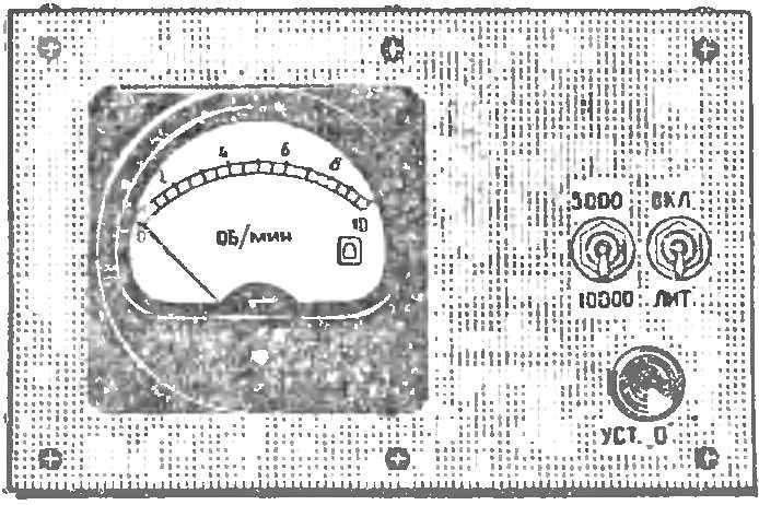
The number of revolutions is desirable to measure and during the training sessions. A feature of this tachometer is to measure the engine speed remotely. For measurements it is sufficient to place the device at a distance of 1-2 m from the running engine. The countdown is on the scale of the microammeter, scaled in revolutions per minute. The instrument has two measurement range: 0-5000 rpm 0 to 10,000 rpm Power tool battery.
THE PRINCIPLE OF OPERATION
When the engine map ignition system emits the so-called impulse interference. Pulse frequency is in a ratio with the number of revolutions. From a single-cylinder engine, mounted on card, one pulse per revolution of the crankshaft. The radio ignition systems accept magnetic, antenna, and then amplified and shaped. Pulse frequency measured by the frequency counter.
SCHEME
Induced in the inductor L1, the RF pulses are amplified UHF two-stage transistors T1 and T2, and then detected through the diodes D1 and D2.
The resulting output of detector pulses fed further to the base of the transistor T3 is a three-stage amplifier WOOFER (T3, T4, T5). The last stage (T5) assembled emitter follower.
With EF pulses in negative polarity is supplied via a diode D3 to the input of the standby multivibrator (T6, T7) acting as a pulse shaper in duration and amplitude.

Fig. 1. Schematic diagram of the electronic tachometer.
Fixed resistors-type ULM-0,12, MLT-0,125, MLT-0,5; a variable resistor R18—SPO-0,5, capacitors C1— C3, C5—FTC; electrolytic capacitor C4—C50-6.
Rectangular pulses from the multivibrator through the buffer stage (T8) is transmitted to the ammeter included in the bridge circuit. The average value of the current flowing through the gauge, is proportional to the pulse repetition frequency and hence the speed of rotation of the crankshaft of the engine map.
Variable resistor R18 is used to set the arrow of the microammeter on the bullets with the engine off. Switching limits of measurement is performed by the switch Q1. In the closed position of the switch B1, the device operates in the range 0— 5000 rpm, when the open — 0-10 000 rpm.
DETAILS AND DESIGN
The L1 coil contains 150-200 turns of wire of 0.1 PALSO. It is wound on a round rod length of 75 mm and Ø 8 mm ferrite 600НН, type М262М or M24 with a current full deflection 100 µa.
The transistors T1 and T2 are any high frequency, for example П401, П402, П403 ГТ305А, ГТ308А and others. The transistors T3—T8 any low frequency, for example МП39, MP40, МП41 and others. Diodes D1—DZ of type D9. Parts are mounted on printed circuit Board size 105X37 mm (Fig. 2).
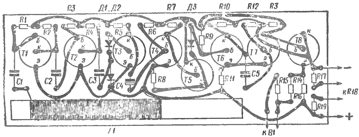
Fig. 2. Placing parts of the PA PCB.
The power to the electronic tachometer is supplied from two series-connected batteries KBS.
ESTABLISHING AND GRADUATIONS
The establishment of the tachometer begins with the selection of resistors R1 and R3. Changing their resistance, make the voltage between the collector and emitter of the transistors T1 and T2 have been established in the range of 4-5 V. Then proceed to the selection of resistors R17 and R19, ensuring that the needle of ammeter was set to zero approximately in the middle position of the handle of the variable resistor R18. You can then proceed to the calibration of an instrument.
The calibration of an instrument is most convenient to produce using the generator of standard signals. The carrier frequency of the GSS is installed approximately in the middle of the wavelength range. The output voltage signal of the generator can be pulsed or sinusoidal modulation.
The modulation frequency is chosen equal to 83 Hz. This frequency corresponds to about 5000 rpm for a single cylinder of the engine map. If the tach works, when you connect a signal generator to the coil L1 of the arrow of the ammeter should deflect by a certain angle. The selection of resistor R14 with the closed position of the switch Q1 to achieve full deflection at full scale. Then set the modulation frequency of 166 Hz, which corresponds approximately to 10 000 rpm, and by the selection of resistor R15 when the open position of the switch Q1 to achieve again the deflection of the ammeter at full scale.
Since the dependence of deflection of ammeter frequency is linear, then the calibration is sufficient to produce only one point on the scale. Electronic tachometer to calibrate and use a mechanical tachometer on the running motor map.
In conclusion, it should be noted that using the same tachometer can measure the rpm of the motorcycle, vehicle or other gasoline engine with a combustible mixture of a spark. It is necessary only to produce a simple peregrimovma tachymeter scale given the fact that the engines are different designs, depending on the number of cylinders and working strokes, one revolution of the crankshaft corresponds to a certain number of pulses.
To make the device universal, we recommend you to install it in the switch, which in series with the microammeter connected additional resistors. The resistors are selected so that the readings are not dependent on the engine design.
A. TEREK, Novosibirsk, Russia
Recommend to read
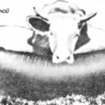 “JACK” COW
What only unexpected use is not find the inflatable design of modern soft materials. The picture shows developed by one of the Australian firms soft "Jack" to lift the weakened animals. ... INSTEAD OF CATERPILLARS — AUGER
Every year more and more intensive is the development of remote areas of the country that holds in its bosom untold wealth, so necessary to the national economy. Finding these hiding...
