In our city of Kingisepp there was a gliding club ROSTO, where I worked as a pilot instructor since 1996. The club had two light aircraft and four gliders. But they were all far from new. ROSTO no longer allocated money for the purchase of new aircraft or repair of old ones. The aircraft equipment fell into disrepair and the club was liquidated in 2000.
For me, life in aviation began at the age of 10, when I joined an aircraft modeling club. He studied aircraft modeling for a long time and seriously, participated in competitions, and received the title of candidate master of sports in aerobatic models and air combat. Then he became a professional pilot: he graduated from the Buguruslan Civil Aviation School in 1986 (and in 2004 from the St. Petersburg Civil Aviation Academy). Therefore, I could not imagine my future life without aviation and decided to build an airplane on my own and with my own money. Few of my old colleagues believed that anything would come of this idea: after all, even building an airplane yourself is not so easy, and you also need to obtain an airworthiness certificate for it, state numbers in order to fly it officially. In the end, having overcome many difficulties and obstacles along the way, I realized my plan and built a two-seat low-wing aircraft with a normal aerodynamic design with a tractor propeller with a VW-1600 Volkswagen engine with a power of 60 hp. air cooled. In October 2002, he made his first flight. In September 2003, the aircraft was registered with the FLA under the designation F-1 and received a tail number.
In the same year, he created the non-profit partnership “Kingisepp Aeroclub “Take Off”, in which new members appeared. Together we bought an An-2 plane – they began to “throw” paratroopers from it, and taught piloting on a homemade plane. The F-1 was flown to all operating airfields in the Leningrad region and even to Tver and Veliky Novgorod.
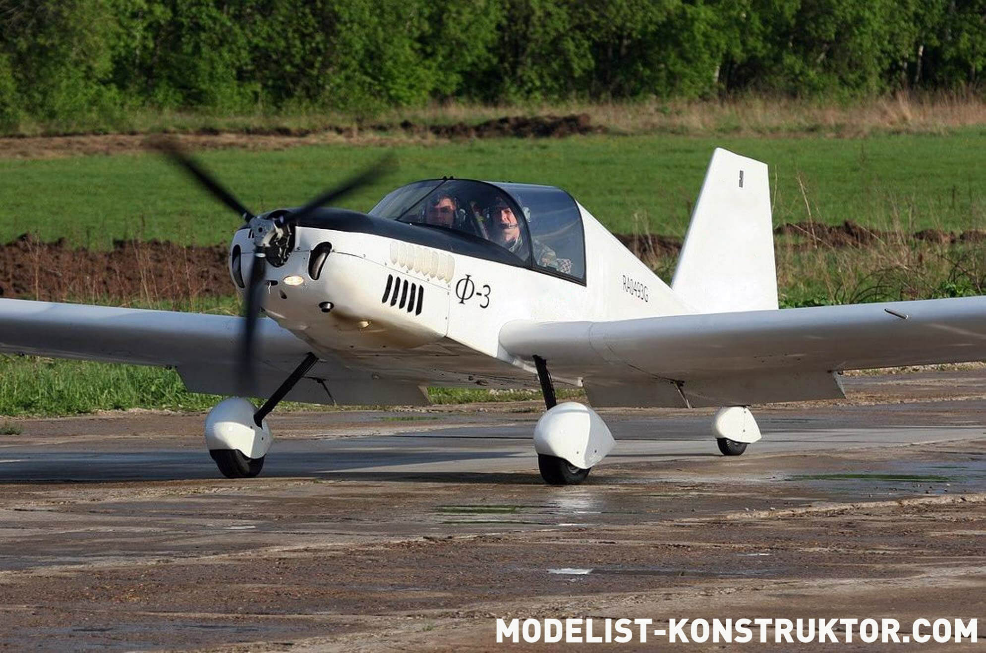
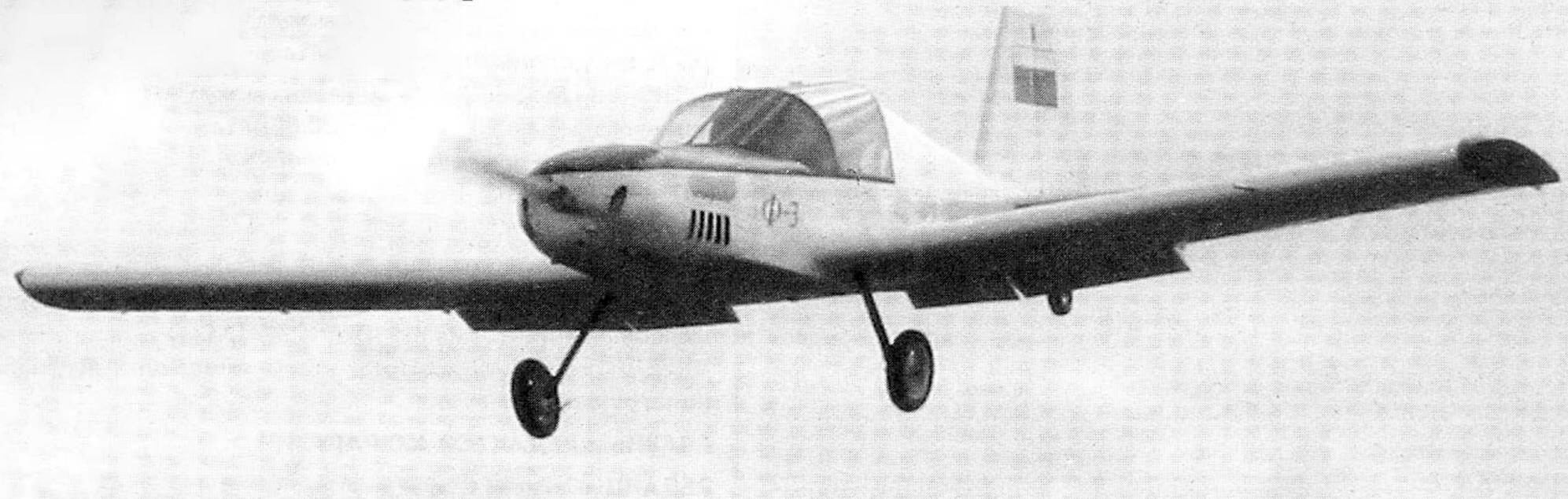
The F-3 aircraft, which will be discussed below, was a development of the previous one – the F-1. I started designing and building the F-3 at the end of 2003. Alexander Chilikin provided me with great assistance in building the aircraft. The F-3 made its first flight in March 2005, and registered it as EEVS GA on 05/17/2007.
The plane is a two-seater, trainer, tourist. According to the aerodynamic design, it is a classic cantilever monoplane with a lower wing and a tail without braces. The structure is wooden, with fiberglass sheathing. For it, we mainly used ready-made sheet fiberglass grade STEF-05 (thickness – 0.5 mm).
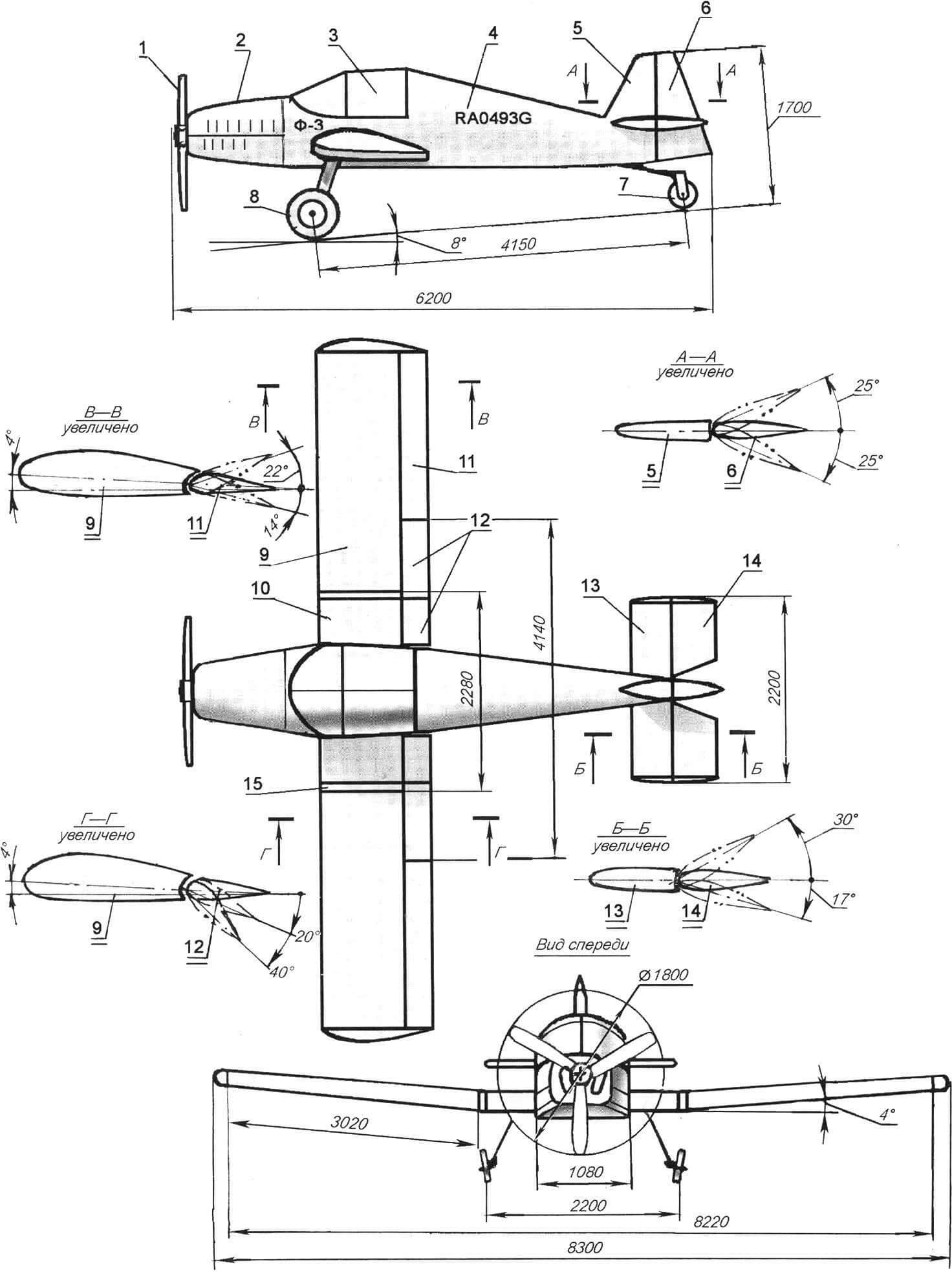
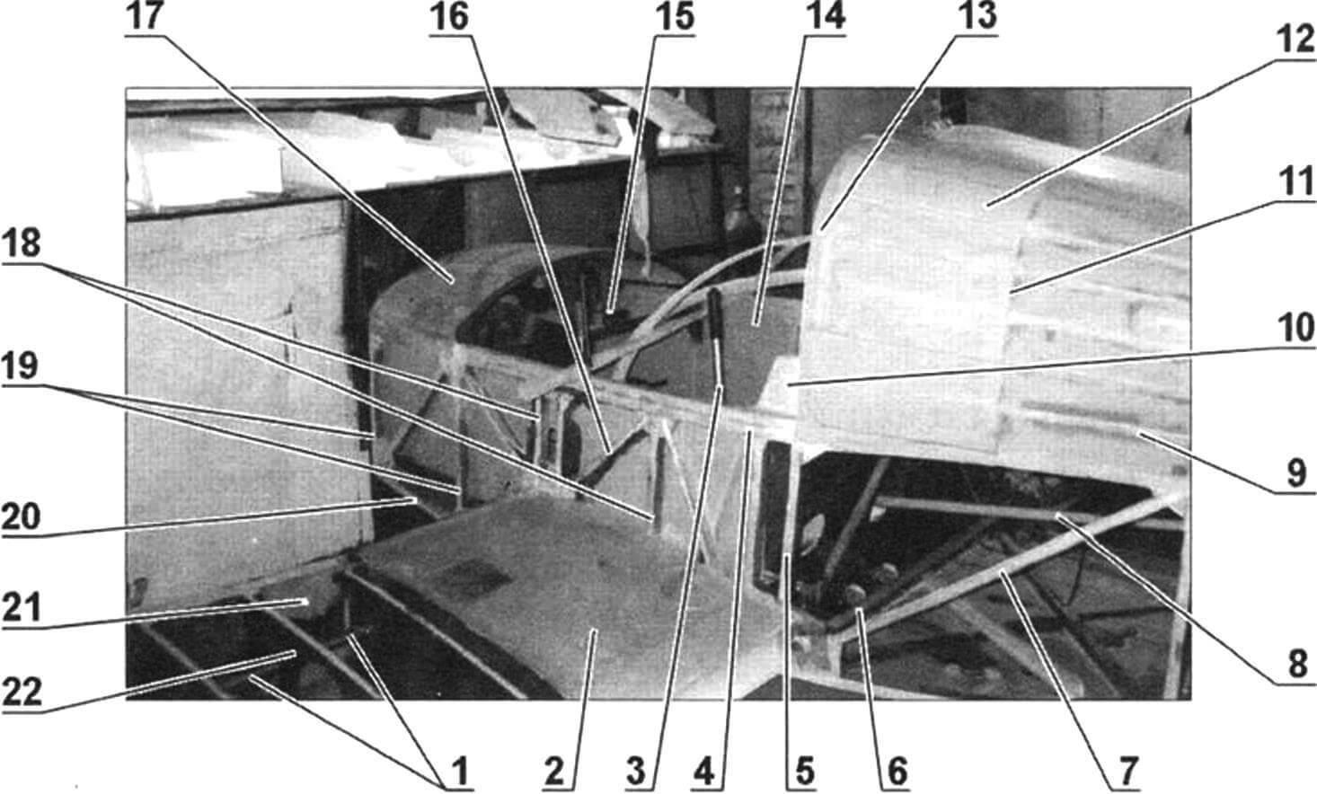
1 — three-blade propeller VFS Ø1800; 2 — engine hood (fiberglass); 3 — cabin glazing; 4 — fuselage; 5 – keel; 6 — rudder; 7 — tail wheel; 8 — chassis; 9 — wing console (2 pcs.); 10 — center section; 11 — aileron (2 pcs.); 12 — flaps (4 pcs.); 13 — stabilizer; 14 — elevator; 15 — overlay (2 pcs.)
The aircraft’s power plant is a Volkswagen VW-2100 engine with a power of 112 hp. at 4800 rpm, four-cylinder, four-stroke, liquid (antifreeze) cooling. Runs on A-95 gasoline.
The motor frame is made of pipe with an outer diameter of 25 mm and a wall thickness of 1.5 mm. The pipe material is steel 20. Rubber shock absorbers are installed at the engine mounting points to the motor mount.
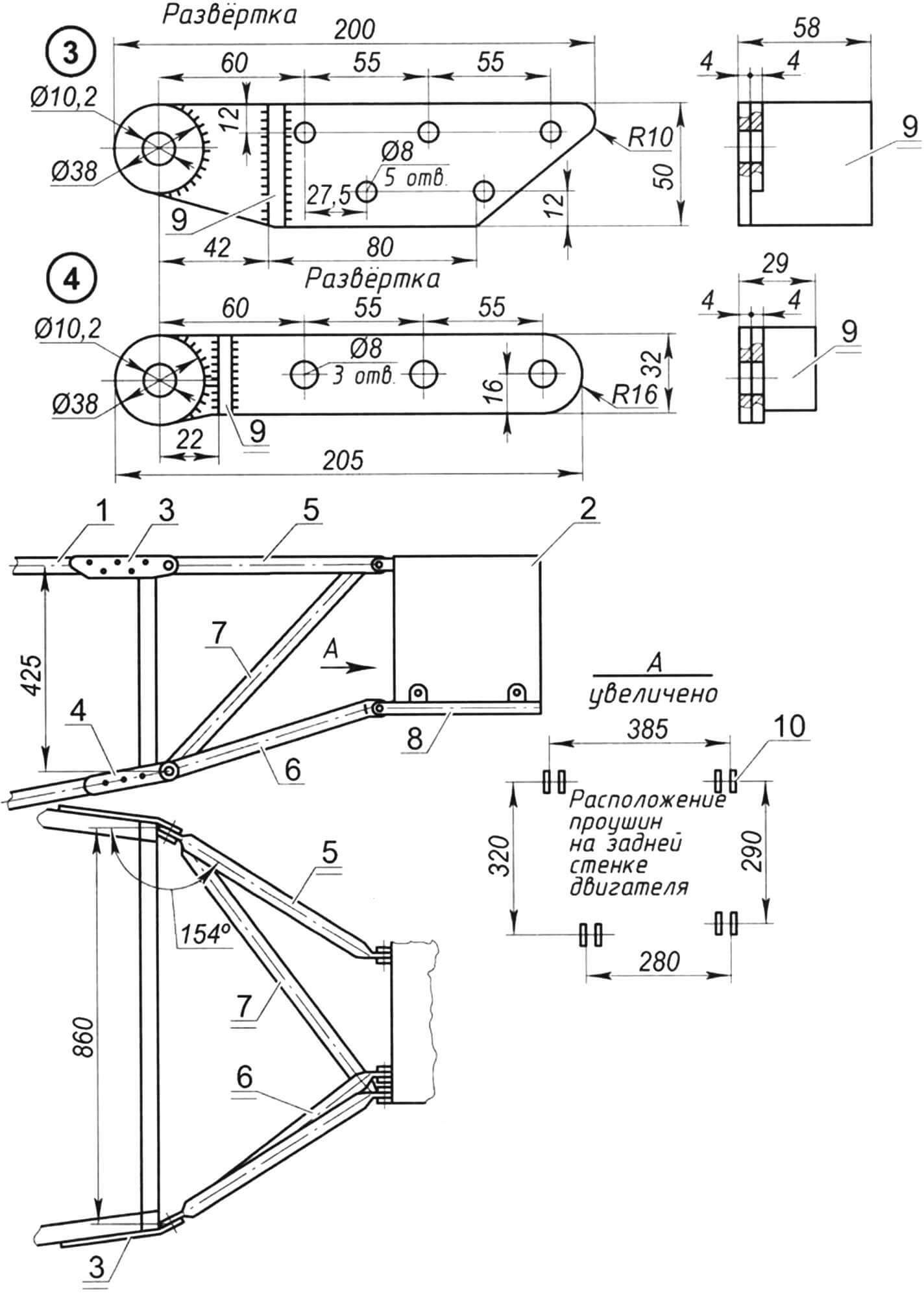
1 — fuselage spar; 2 – engine; 3 — upper eyelet for fastening the engine mount elements to the fuselage (steel, sheet s4, 2 pcs.); 4 — lower eyelet for fastening the engine mount elements to the fuselage (steel, sheet s4, 2 pcs.); 5 — extension (steel pipe Ø25, 2 pcs.); 6 — spacer (pipe Ø25, 2 pcs.); 7 — strut (pipe Ø25); 8 — sub-engine connection (pipe Ø25, 2 pcs.); 9 — stop (steel, sheet s4); 10 — location of the lugs on the rear wall of the engine
Rotation from the engine output shaft to the propeller shaft is carried out through a gear reducer with a gear ratio of 2.05.
The propeller is factory-made, three-bladed, pitch variable and fixed on the ground, brand VFSh-183/1800 (the diameter of the surface it sweeps is 1800 mm). The blades are fiberglass. Static thrust of the propeller in takeoff mode is 200 kgf.
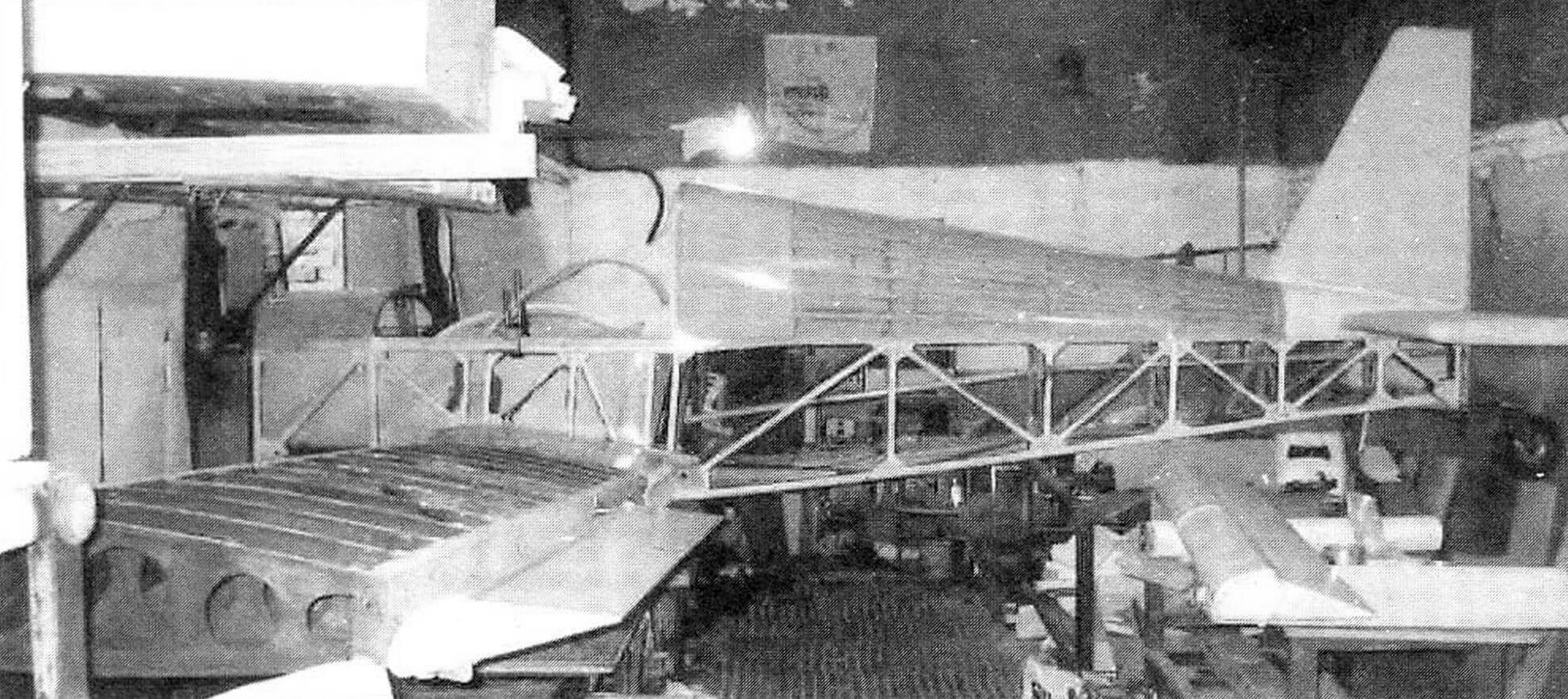
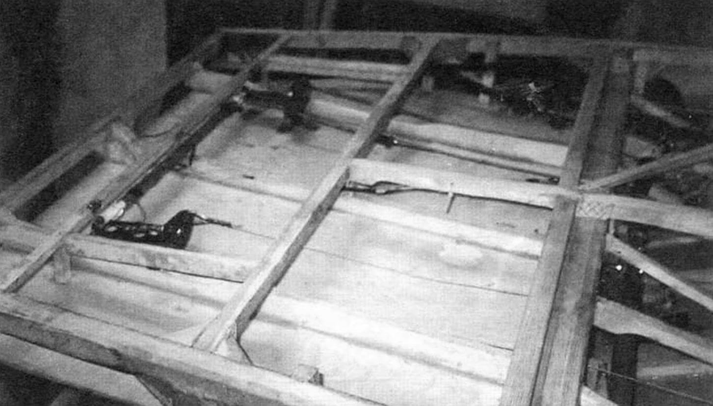
The fuselage of the aircraft is made of wood and has a truss structure. All its power elements (spars, braces, frames) are made of high-grade wood – straight-layered pine beams without knots with proven tensile strength (830 kg/cm2) and compressive strength (350 kg/cm2). All units were glued using K-153 epoxy resin with a tensile strength of 80 kg/cm2. The joints were reinforced with triangular inserts also 25 mm thick.
The frames are made of bars with a cross-section of 25×25 mm in the form of rectangular frames. The front frame is covered with a fireproof partition made of duralumin (D16T) sheet 2 mm thick. In the corners, at the points where the front ends of the side members meet the first frame, units for attaching the motor mount are installed – steel brackets-ears, reinforced with washers welded to them.
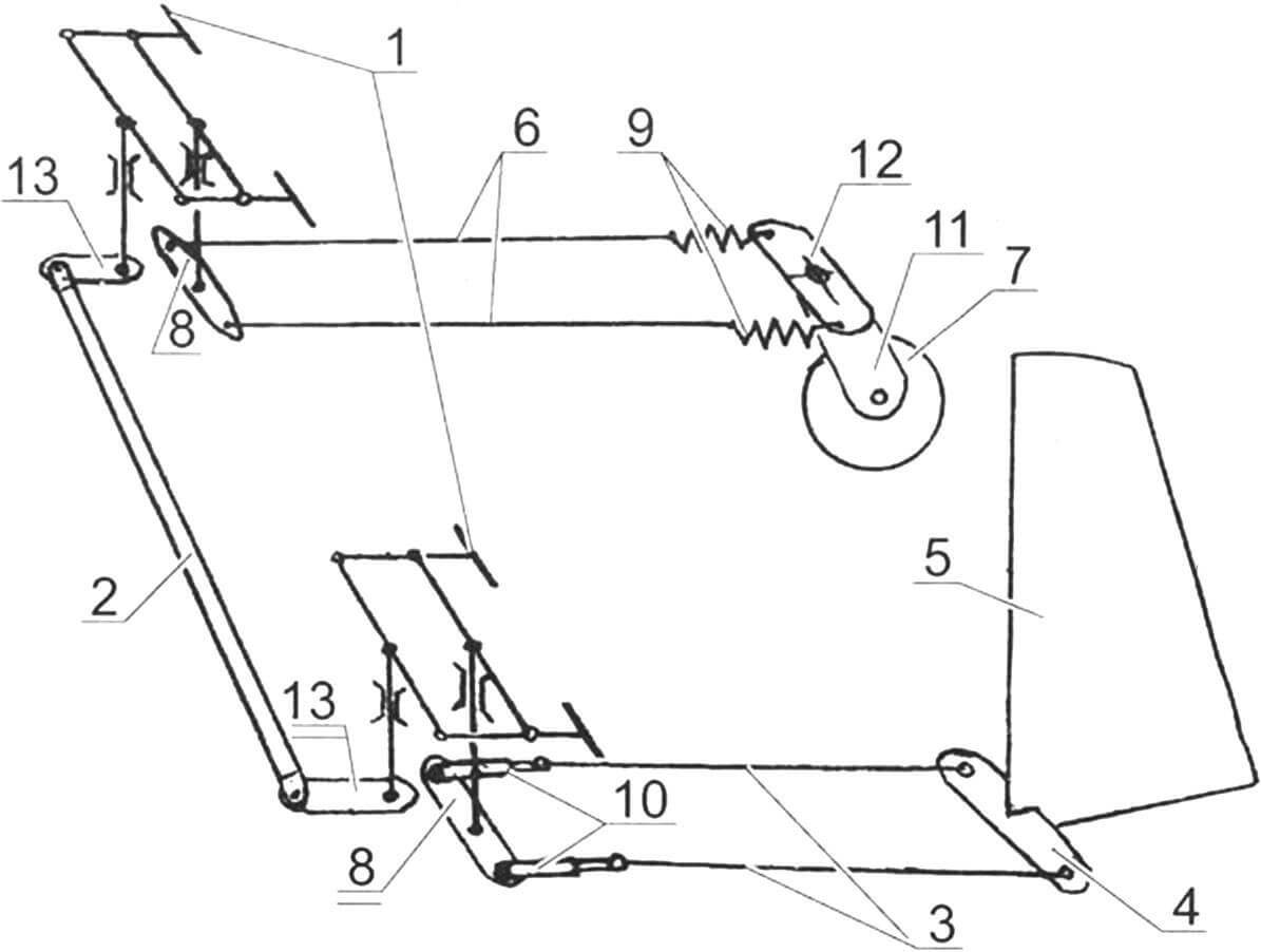
1 — fuselage; 2 — main center section spar; 3 — main spar of the wing console; 4 — welded bracket for fastening the spring to the main center section spar (steel, sheet s4); 5 — spring (section 90×14 from a KamAZ vehicle); 6 — lower eyelet of the center section and wing console docking unit (8 pcs.); 7 — upper eyelet of the center section and wing console docking unit (8 pcs.); 8 — welded bracket for fastening the main wheel to the spring (steel, sheet s4); 9 — brake drum; 10 — main wheel; 11 — rear center section spar; 12 — rear console spar; 13 — fastening the console suspension unit to the center section (M16 bolt, 4 pcs.)
The upper spars from the first to the third frame (in the area of the cabin) are reinforced – made of two bars that are united in height and glued together. Also on the sides of the cabin between the second and third frames, on both sides of each center section frame, there are mounted racks supported by struts. The struts, like the third frame, are fixed at an angle of 4° to the vertical – according to the angle of the wing.
The third frame also serves as a support for the seat back. On top of the same frame there is a safety arch with a height of 510 mm, made on a mandrel made of plywood pine bars. The center section spars serve as support for the seat itself. In addition, the seat is reinforced with its own posts, crossbars and struts, fastened together with gussets (triangular inserts) made of epoxy resin.
Table 1.
| No. | Frame height | Frame width | Distance from the first frame |
|---|---|---|---|
| 1 | 475 | 945 | 0 |
| 2 | 533 | 1047 | 425 |
| 3 | 565 | 1080 | 1495 |
| 4 | 498 | 813 | 2225 |
| 5 | 433 | 618 | 2775 |
| 6 | 378 | 460 | 3225 |
| 7 | 330 | 318 | 3625 |
| 8 | 285 | 185 | 4000 |
| 9 | 255 | 80 | 4240 |
In total, the fuselage has nine frames. The dimensions of their frames and location along the length of the fuselage are shown in Table 1.
To form the fuselage garrot, arches made of 3 mm plywood are installed on top of the fourth, fifth, sixth and seventh frames, similar in shape to a safety arc, fastened together with stringers made of pine slats with a cross-section of 10×10 mm.
Another bow is mounted between the 3rd and 4th frames.
The fuselage skin is made of ready-made fiberglass sheets, glued to the frame elements with an epoxy binder, with preliminary sanding of the joined edges to give them roughness.
The hood consists of lower and upper covers glued from fiberglass on K-115 epoxy resin in foam matrices.
Table 2. Profile NACA-23018, C=18
| x, % | 1.25 | 2.5 | 5.0 | 7.5 | 10 | 15 | 20 | 25 | ZO | 40 | 50 | 60 | 70 | 80 | 90 | 100 |
|---|---|---|---|---|---|---|---|---|---|---|---|---|---|---|---|---|
| HC, % | 4.01 | 5.33 | 7.07 | 8.28 | 9.17 | 10.22 | 10.7 | 10.9 | 10.86 | 10.31 | 9.29 | 7.93 | 6.3 | 4.48 | 2.45 | 0 |
| un, % | 1.97 | 2.7 | 3.65 | 4.33 | 4.91 | 5.81 | 6.49 | 6.86 | 7.15 | 7.1 | 6.6 | 5.77 | 4.69 | 3.4 | 1.9 | 00 |
The aircraft wing has a NASA-23018 profile, the data for which is given in Table 2.
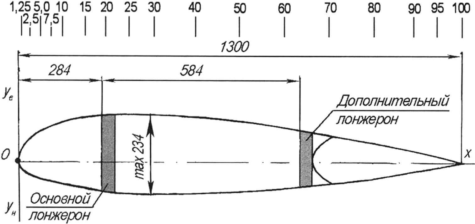
The wing is straight without tapering, two-spar, technologically divided into a center section and consoles. The front spar takes up about 70% of the load, the second rear spar takes about 30%. The spars are box-shaped, their upper shelves are made of plywood pine bars, the lower shelves of the main ones are made of ordinary ones, the auxiliary ones are also made of plywood, the walls are made of 3 mm plywood. Along the span of the wing, the shelves of the console spars are lighter – they are reduced in height from the inside.
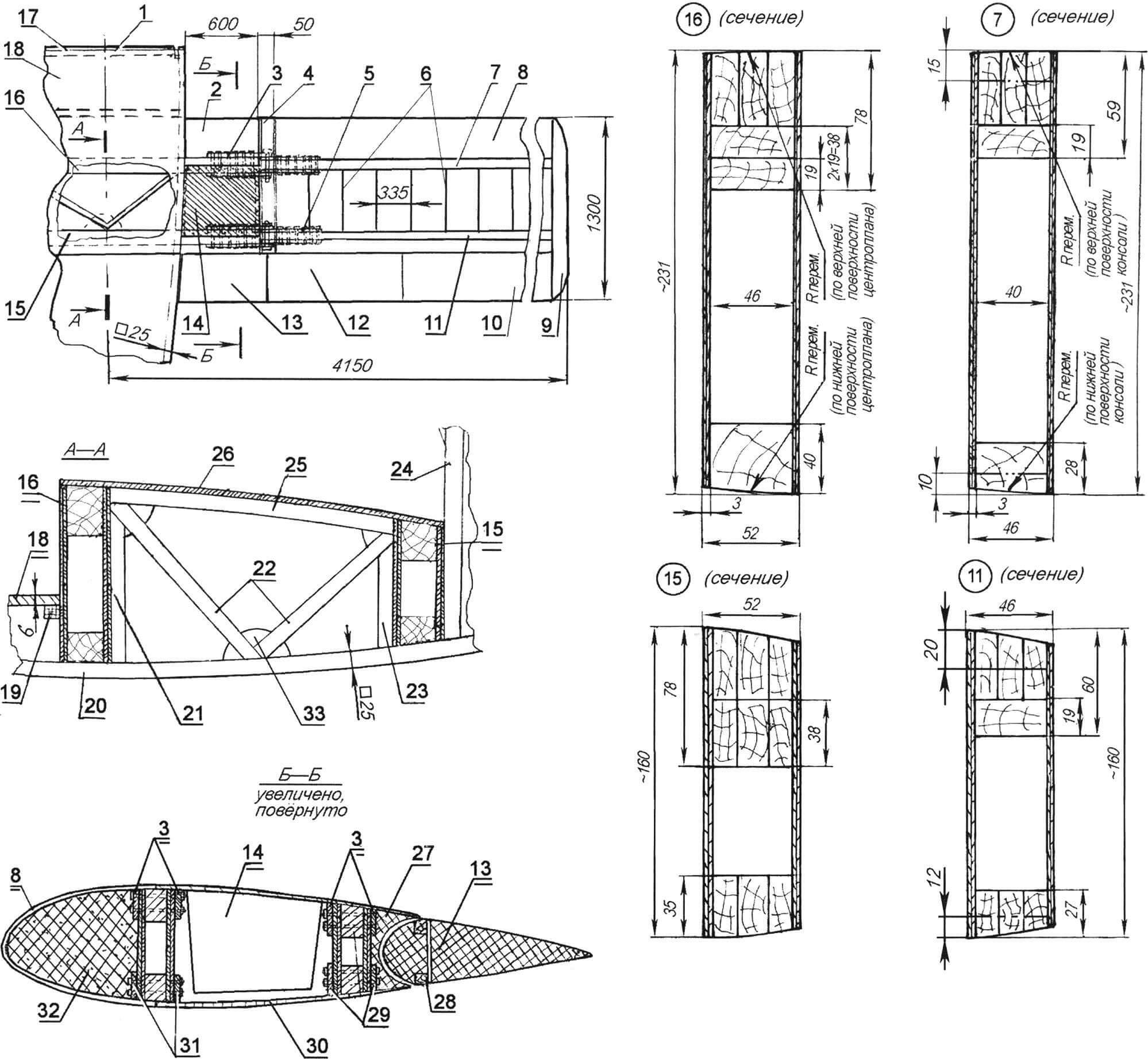
1 — fuselage; 2 — center section; 3 — upper front junction of the wing console and the center section (2 pcs.); 4 — overlay; 5 — upper rear junction of the wing console and the center section (2 pcs.); 6 — wing console ribs; 7 — front spar of the console; 8 — wing toe; 9 — wing tip (foam, 2 pcs.); 10 — aileron (2 pcs.); 11 — rear console spar; 12 — wing console flap (2 pcs.); 13 — center section flap (2 pcs); 14 — fuel tank; 15 — rear center section spar; 16 — front center section spar; 17 — fire partition; 18 — cabin floor; 19 — floor support; 20 — fuselage spar (block 25×25, 2 pcs); 21 — front seat pillar (block 25×25, 2 pcs); 22 — seat struts (block 25×25, 4 pcs.); 23 — rear seat pillar (block 25×25, 2 pcs); 24 — frame No. 3; 25 — seat support (block 25×25, 2 pcs); 26 — seat (plywood); 27 — insert (foam); 28 — flap spar; 29 — lower rear junction of the wing console and the center section (2 pcs); 30 — center section skin (fiberglass STEF-05); 31 — lower front junction of the wing console and the center section (2 pcs) 32 — sock filler (foam); 33 – scarf
The profile-forming ribs are made of 3 mm plywood, lightened with round holes and reinforced from the front to the rear spar with pine bows with a section of 15×15 mm. Wing area – 10.8 m2, chord – 1300 mm. The installation angle of the wing and its transverse V are the same – +4° each.
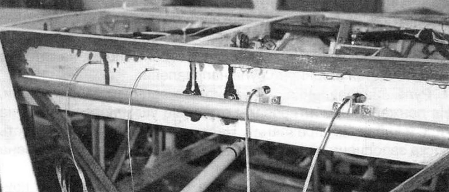
In the center section (between the side members) on both sides of the fuselage there are two fuel tanks with a total capacity of 80 liters (40 liters each). The tanks are welded from a steel sheet 1 mm thick and connected to a supply tank with a capacity of 1 liter by rubber hoses with a diameter of 16 mm.
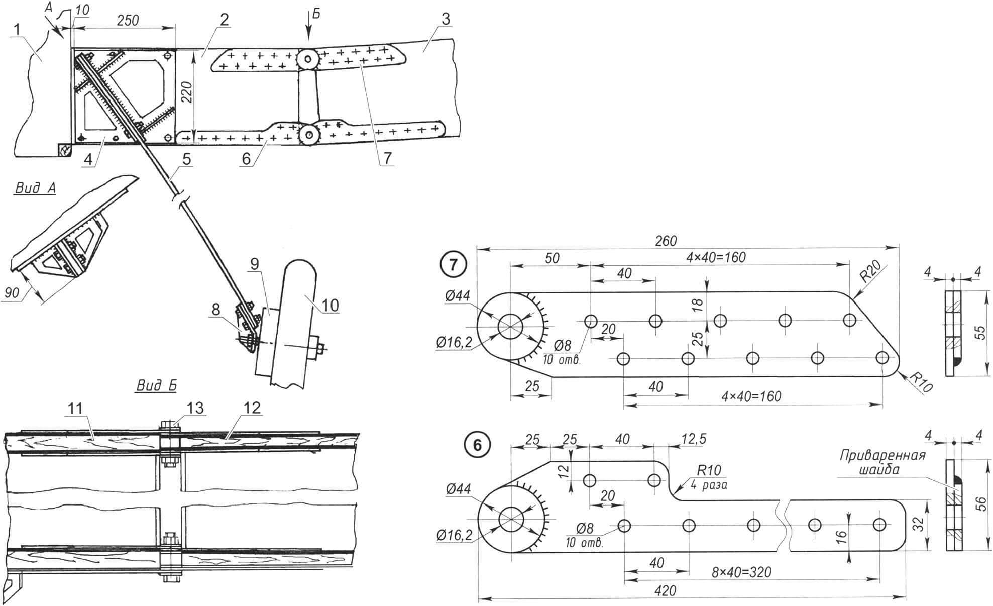
1 — aircraft control stick; 2 — main thrust; 3 — intermediate rocker (2 pcs.); 4 — differential rocker (2 pcs.); 5 — aileron thrust (2 pcs.); 6 — aileron mounting lugs on the wing console (6 pcs.); 7 — aileron (2 pcs.)
The wing tip is located at a distance of 284 mm from the first frame. The cavities between the ribs in the wing toe are filled with foam. The wing tips, as well as the rear inserts, are also foam. The skin of the center section and consoles is made of fiberglass, and from the front to the rear spar it is made of the same ready-made STEF-05 fiberglass sheet that was used for the fuselage skin.
The hinge units of the wing and center section consoles are made of steel plates 4 mm thick in the form of counter lugs, fixed to the upper and lower flanges of the side members, and so as to ensure an installation angle of the consoles relative to the center section of +4°. The holes in the eyes for the connecting bolts are reinforced with welded washers.
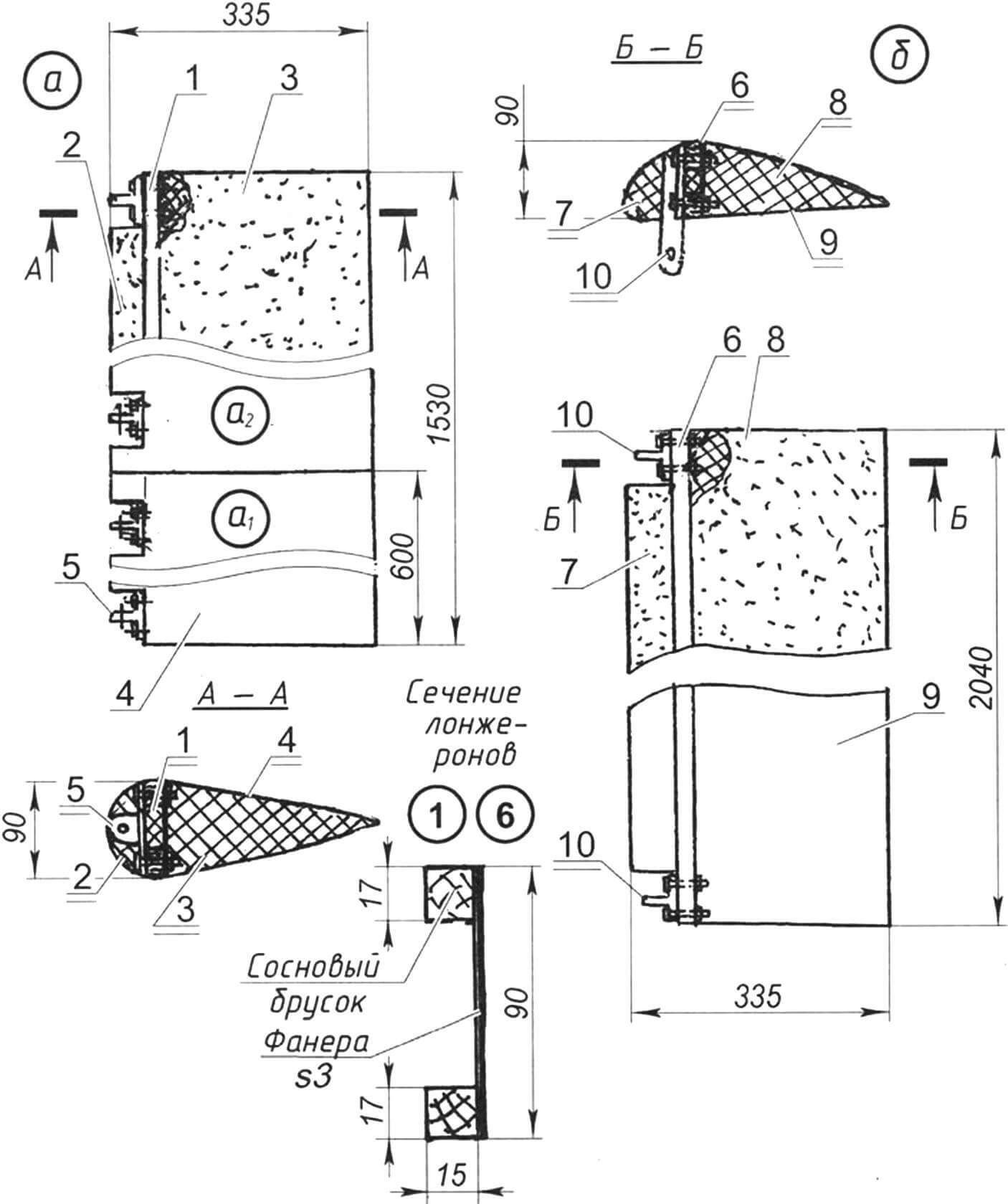
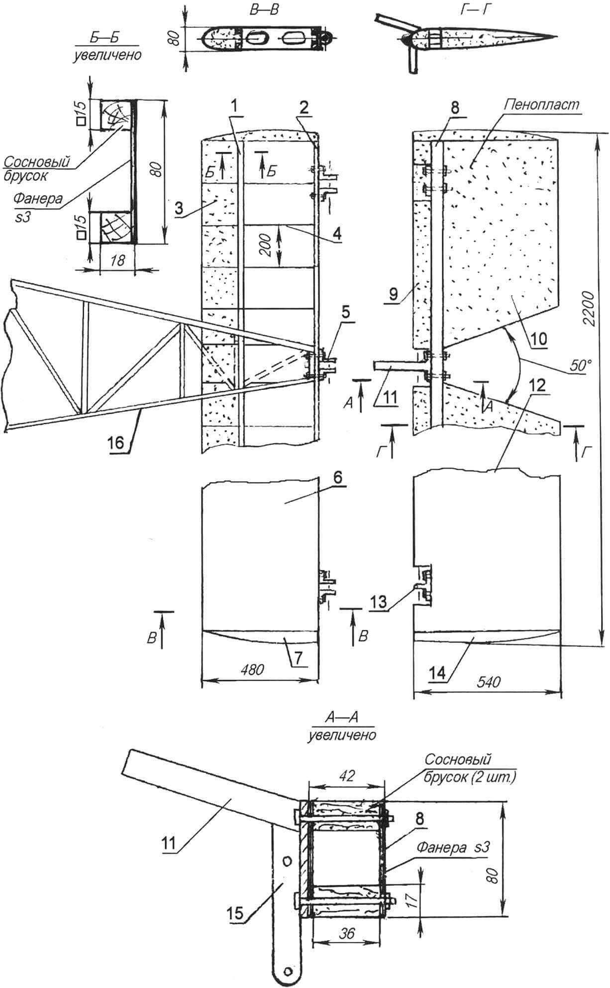
1 — flap spar; 2 — flap toe; 3 — flap; 4 — sheathing (two layers of fiberglass with epoxy binder); 5 — eyelet for attaching the flap to the wing (4 pcs.); 6 — aileron spar; 7 — aileron toe; 8 — aileron; 9 — sheathing (two layers of fiberglass with epoxy binder); 10 — eye-bracket for aileron mounting on the wing (2 pcs.)
The ailerons and flaps are the same in design – made of polystyrene foam with wooden U-shaped spars (shelves are made of pine bars, and the walls are made of 3 mm plywood) and covered with fiberglass.
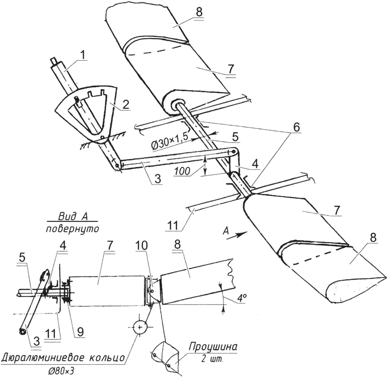
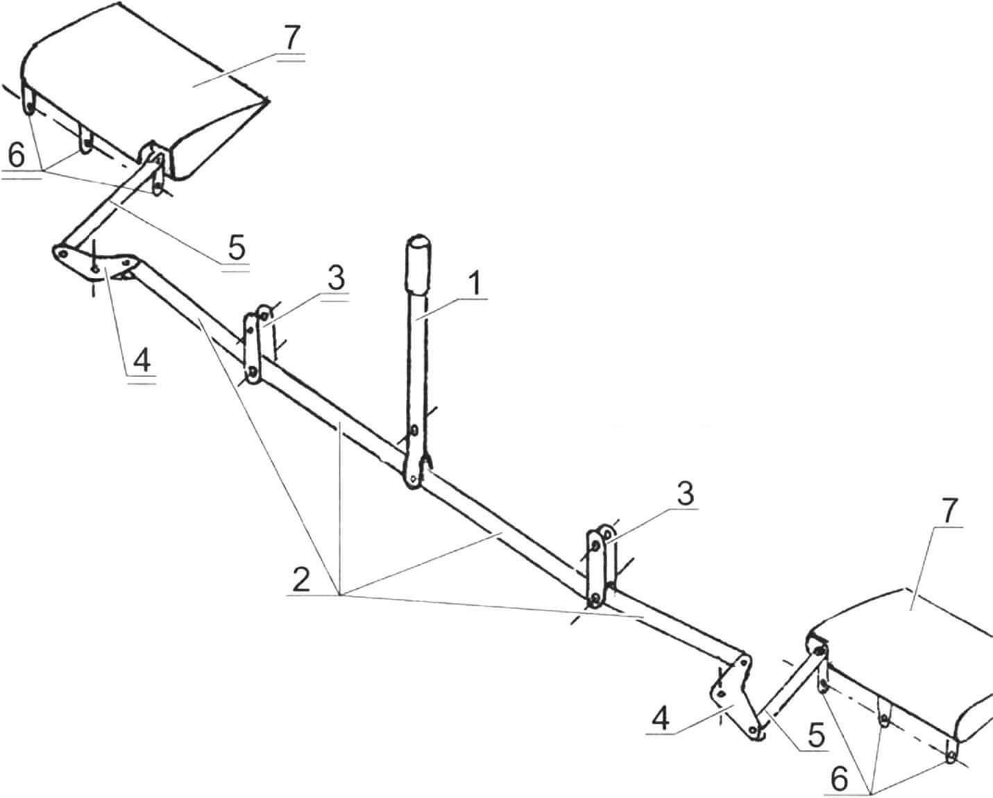
1 — control knob; 2 — lock for disabling flaps in 3 positions; 3 — thrust of the flap control handle; 4 – rocking chair; 5 — flap rotation shaft (duralumin pipe Ø30×1.5); 6 — bearings (2 pcs.); 7 — center section flap (2 pcs.); 8 — wing console flap (2 pcs.); 9 — connection of the shaft and the center section flap (2 pcs.); 10 — cardan joint connecting the center section flaps and the wing console (2 pcs.); 11 — fuselage
The flaps are composite (center section and cantilever). They are connected to each other by cardan joints.
The horizontal tail includes a stabilizer and elevator. The stabilizer is cantilever, its design is the same as the wing: two-spar, with plywood ribs, reinforced with pine slats (section 10×10 mm). The sock is made of foam plastic and covered with fiberglass on epoxy resin in two layers. The endings are also foam plastic, pasted over. The stabilizer is attached to the upper spars and the last two frames of the fuselage, and is also connected to the rear (additional) spar and the lower fin rib. The elevator is hingedly mounted on the rear spar of the stabilizer, for which three eyes are mounted on the spar.
1 — main spar of the stabilizer; 2 — auxiliary stabilizer spar; 3 — stabilizer toe filler (foam); 4 — rib (s3 plywood, 10 pcs.); 5 — elevator suspension eye (3 pcs.); 6 — stabilizer casing (fiberglass); 7 — stabilizer end (2 pcs.); 8 — elevator spar; 9 — toe of the elevator; 10 — elevator blade (foam, 2 pcs.); 11 — counterweight; 12 — elevator trim (fiberglass); 13 — eyelet for attaching the elevator to the stabilizer (3 pcs.); 14 — end of the elevator (2 pcs.); 15 — elevator hog; 16 — fuselage
The elevator is single-spar, the tip and tail are made of foam plastic. Covered with fiberglass cloth and epoxy binder. It consists of two parts, interconnected by one spar. The spar is box-type. The lower and upper shelves are made of solid pine bars, and the walls are all made of the same 3 mm plywood. The response lugs of the suspension to the stabilizer are mounted on the spar. Along with the middle eye, the elevator counterweight and the steering wheel control horn are also mounted. The counterweight weight is lead.
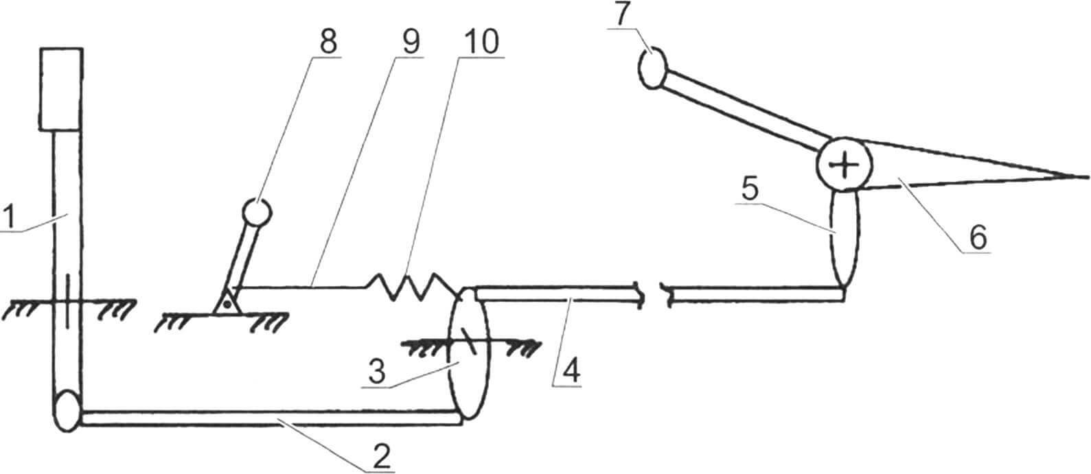
1 — aircraft control stick; 2 — front (short) thrust; 3 – rocking chair; 4 — rear (long) rod; 5 — elevator hog; 6 — elevator; 7 — elevator weight compensator; 8 — trimmer handle; 9 — trimmer cable; 10 — trimmer spring
The vertical tail consists of a fin and rudder. The keel is two-spar, structurally connected to the fuselage: its front spar passes through the frame and is fastened to the lower beam of the seventh frame, and is also mounted between the upper spars using longitudinal foam inserts covered with fiberglass. The rear keel spar is a column on which the rudder is hinged.
1 — aileron control rod; 2 — left fuel tank; 3 — aircraft control stick (RUS); 4 — upper spar (reinforced part); 5 – third frame; 6 — flap control shaft; 7 — fuselage frame strut; 8 — elevator control rod; 9 — gargrot stringer; 10 — seat; 11 — gargrot bow; 12 — gargrot covering; 13 — safety arc; 14 — interior lining of the cabin; 15 — installation location of the instrument panel; 16 — strut of the center section strut; 17 — instrument compartment; 18 — racks; 19 — frames (first and second); 20 — lower fuselage spar; 21 — wing console spar; 22 — wing console rib
The rudder is of a single-spar design. The response lugs for the rudder linkage to the keel and control horn are mounted on the spar. The ribs are made of plywood. The sock cavity is filled with foam. The entire surface of the steering wheel is covered with two layers of fiberglass.
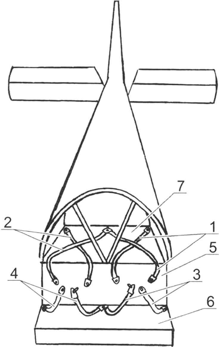
1 — pilot pedals (2 pairs); 2 — interpedal traction; 3 — rudder control cables; 4 — rudder rocker; 5 — rudder; 6 — rear wheel control cables; 7 — rear wheel; 8 — rocking pedals (2 pcs.); 9 — damping springs; 10—tanders; 11— tail support-fork; 12 — tail wheel rocker; 13 — rocker of interpedal traction (2 pcs.)
The aircraft chassis is a three-porcine, with a tail wheel, adapted for the operation of the aircraft from the soil take-off and landing stripes. The main support is spring type, equipped with two brake wheels of 400 × 120 mm dimensions. Two struts-priests with a section of 90 × 14 mm 850 mm long are used from KAMAZ car. The springs to the main spar of the centrooplan is carried out with the help of a welded bracket from steel (30 kgs) sheet with a thickness of 4 mm. With the help of another (also welded) bracket, the main wheel axis is attached to the lower end of the springs.
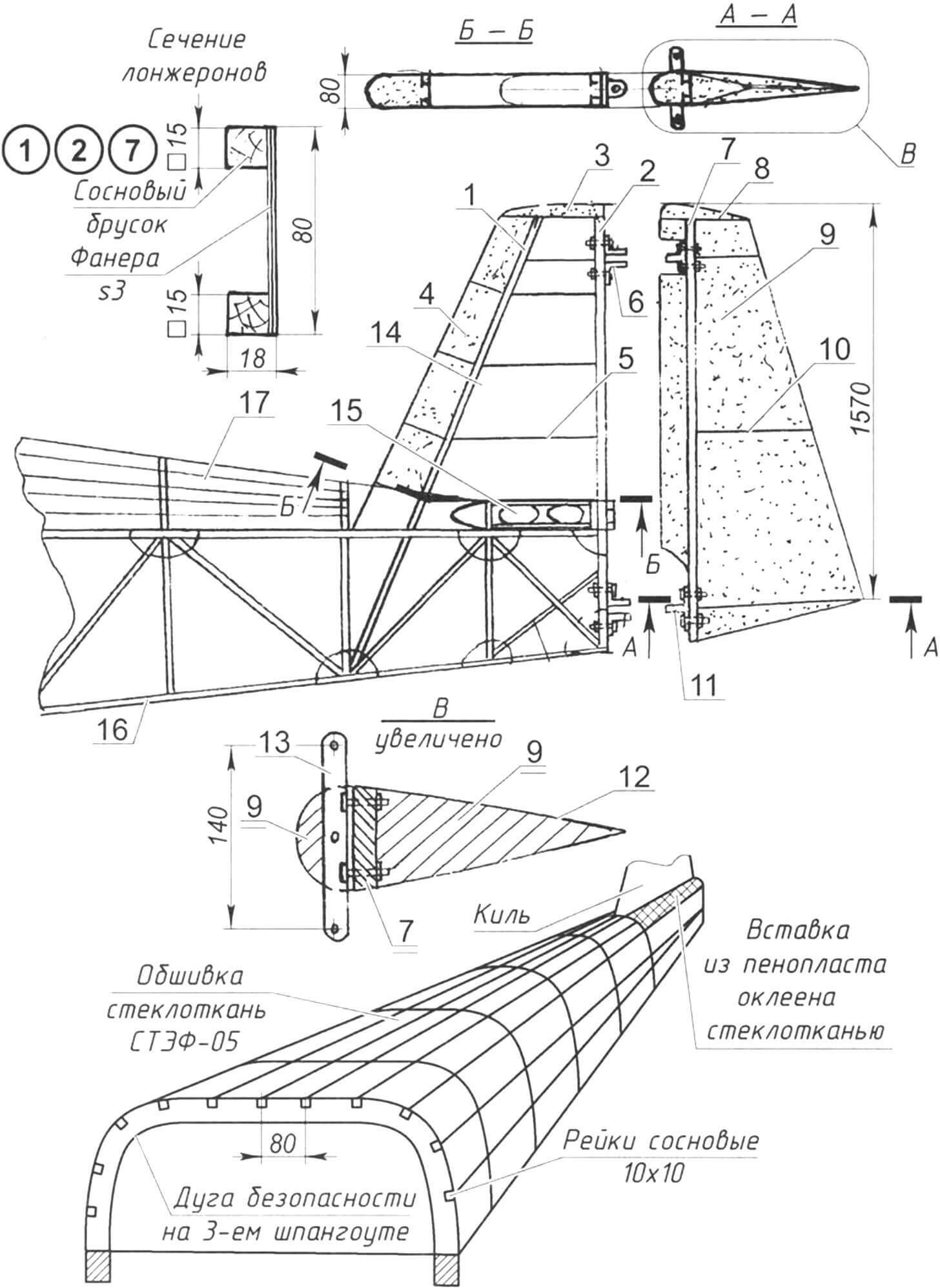
1 – anterior (strut) spar; 2 – posterior spar; 3 – keel -terminal; 4 – stabilizer sock filler (foam); 5 – keel nervous (plywood S3); 6 – eye to hover the steering wheel of direction (2 pcs.); 7 – the spine of the steering wheel; 8 – keel -tie (polystyrene foam covered with two layers of fiberglass on an epoxy binder); 9 – aggregate (foam); 10 – nervous (3 pcs.); 11 – the ear of the hitch of the steering wheel of direction on the keel (2 pcs.); 12 – lining of the steering wheel (two layers of fiberglass on an epoxy binder); 13 – rocking steering; 14 – keel sheathing (two layers of fiberglass on an epoxy binder), is not conventionally shown; 15 – stabilizer; 16 – fuselage frame; 17 – Gargrot
The size of the tail wheel is 250 × 80 mm. The tail support is also a car spring sheet, only with a cross section of 80 × 10 mm and shorter (its length is 420 mm). Attached at one end to the fuselage with two M10 bolts. At the other (rear) end, the wheel fork with a cabanic of control named after
The wheels of the main supports of the chassis are equipped with drum brakes. They are driven through the cables from the trunk with the left pilot and from the pedals with the right pilot.
All wheels are later equipped with fairings excreted in a foam matrix made of fiberglass on an epoxy binder.
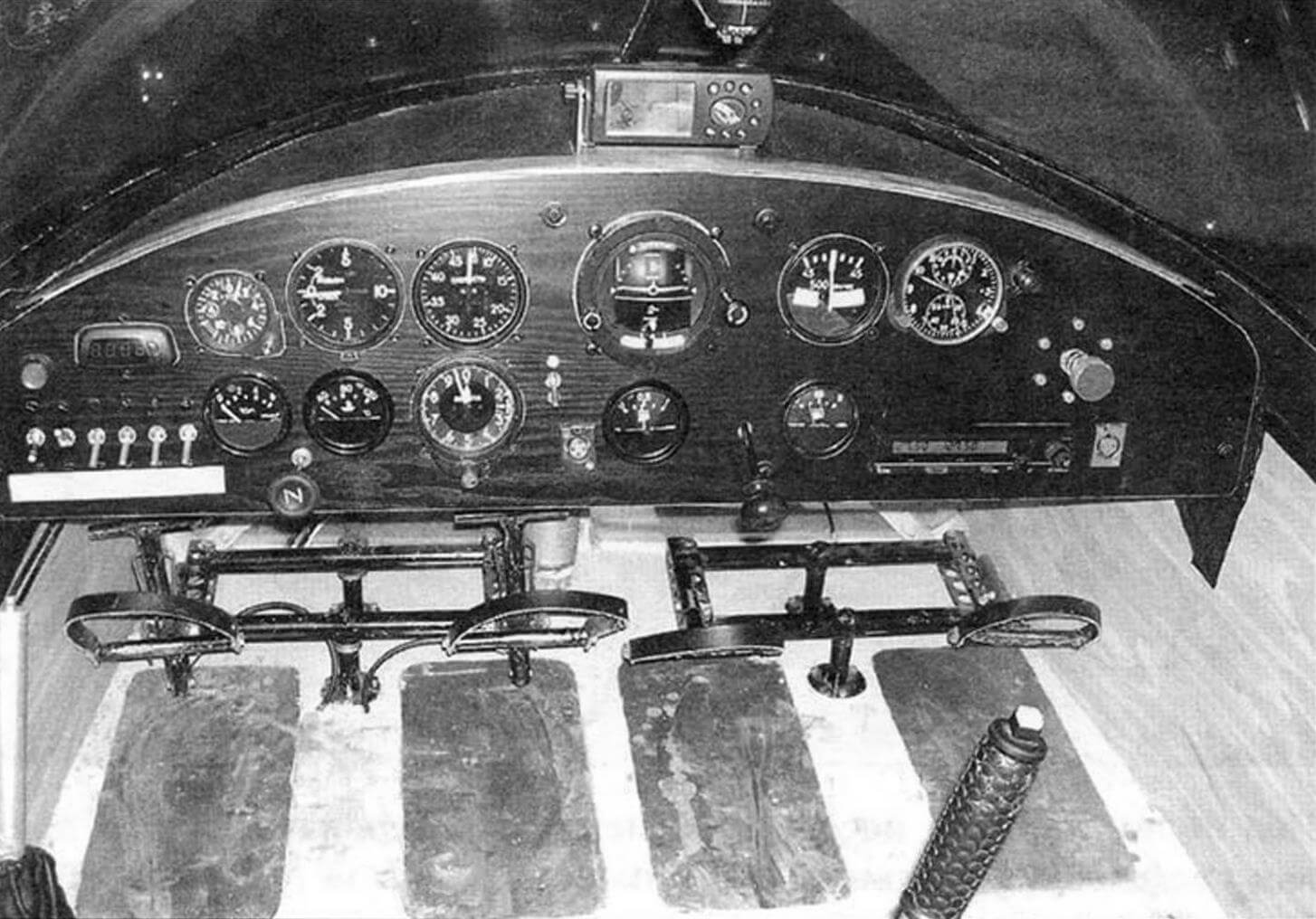
The cabin of the aircraft is double, with the location of the pilots “Bok Open”, is located between the first and third frames. On the upper cross member of the second frame, the dashboard is fixed. The pilots seat – foam rubber, with a base from plywood, lined with fabric “Flok” on top, which car seats are sheathed, equipped with tiered belts. All their fastening points are associated with the power elements of the fuselage structure. The sides of the cabin are also sheathed from the inside with fiberglass Stuf-05. The floor of the cab is from the 6-mm plywood, rubber rugs are glued under the pedals.
1 – shoulder belts of the left pilot; 2 – shoulder belts of the right pilot; 3 – belt belts of the left pilot; 4 – belts of the right pilot; 5 – the back of the pilots seat; 6 – pilots seat; 7 – shelf
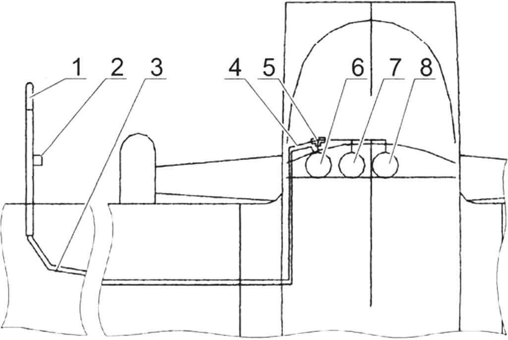
1 – receiver of full air pressure; 2 – receiver of static air pressure; 3 – full pressure hose; 4 – static pressure hose; 5 – boss (tee) of static pressure; 6 – speed indicator; 7 – altitude; 8 – variometer
Glazing of a cabin made of Plexiglas 3 mm thick. Lanter – with two parts leaning upwards (such as a “seagull”).
The aircraft control handle (RUS), mounted on the floor of the cabs between the pilots. The opening of the throttle of the engine carburetor is carried out from the engine control handle (ore) installed on the left side of the cab. There is also a handle of control of the trimmer of the steering wheel of heights, and next to the floor is the shuttle control handle.
Power supply of equipment and devices provide: the battery at 12 in a capacity of 38 a/h; A 12 kW generator in a capacity of 1 kW, three converters for 36 in x 400 Hz.
The aircraft has an IC-A200 radio station on board, as well as the necessary set of piloting and navigation devices for flight in simple weather conditions.
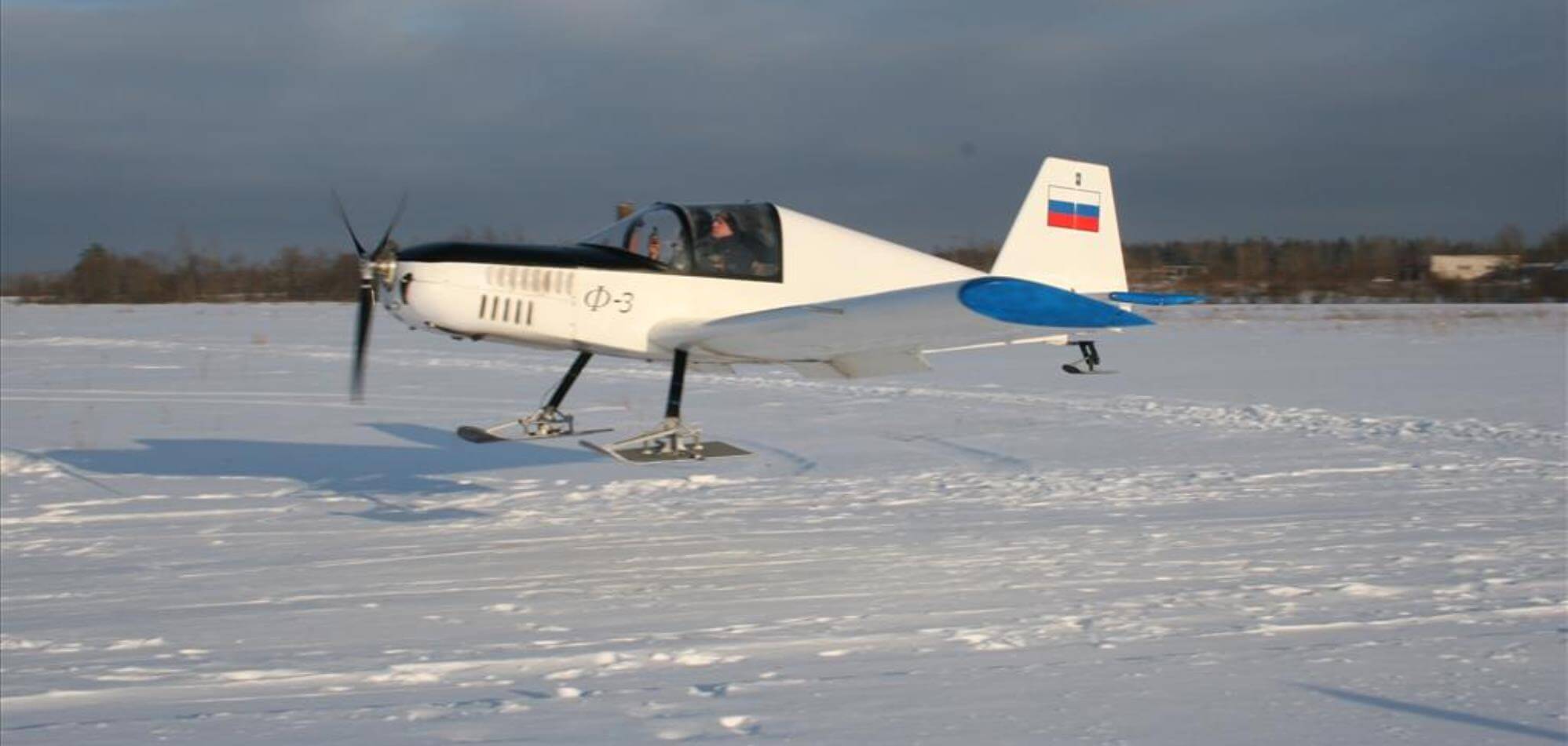
F-3 in the winter is equipped with a ski chassis and operated from snow-capped airfields. Ski – duralumin.
The aircraft is refueling through the neck in the left tank with the flow of fuel through the consumable tank – into the right.
The main flight technical characteristics
Rules, kg 700
The mass is empty, kg 442
Speed, km/h.
cruising 150
maximum 180
dumping 75
Value, m/s 3
Run length, m 180
Mileage length, m 150
Maximum flight range, km 600
Maximum flight duration, h 6
Practical ceiling, m 3000
Calculation overload, G +3 / -1.5
O. FEFELOV, G. KINGISEPP
Recommend to read
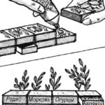 GARDEN IN A BOX
Usually vegetable seeds, berry and horticultural crops are kept in bags, which is not very convenient. Much handier to keep them in a special box with drawers. It is easy to make from...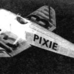 COPY PIXIE ELECTRIC
Bold, uncomplicated and, importantly, "volatile" model-copy will work if you choose as a prototype little-known light aircraft of the series Pixie. Just check for yourself what...
