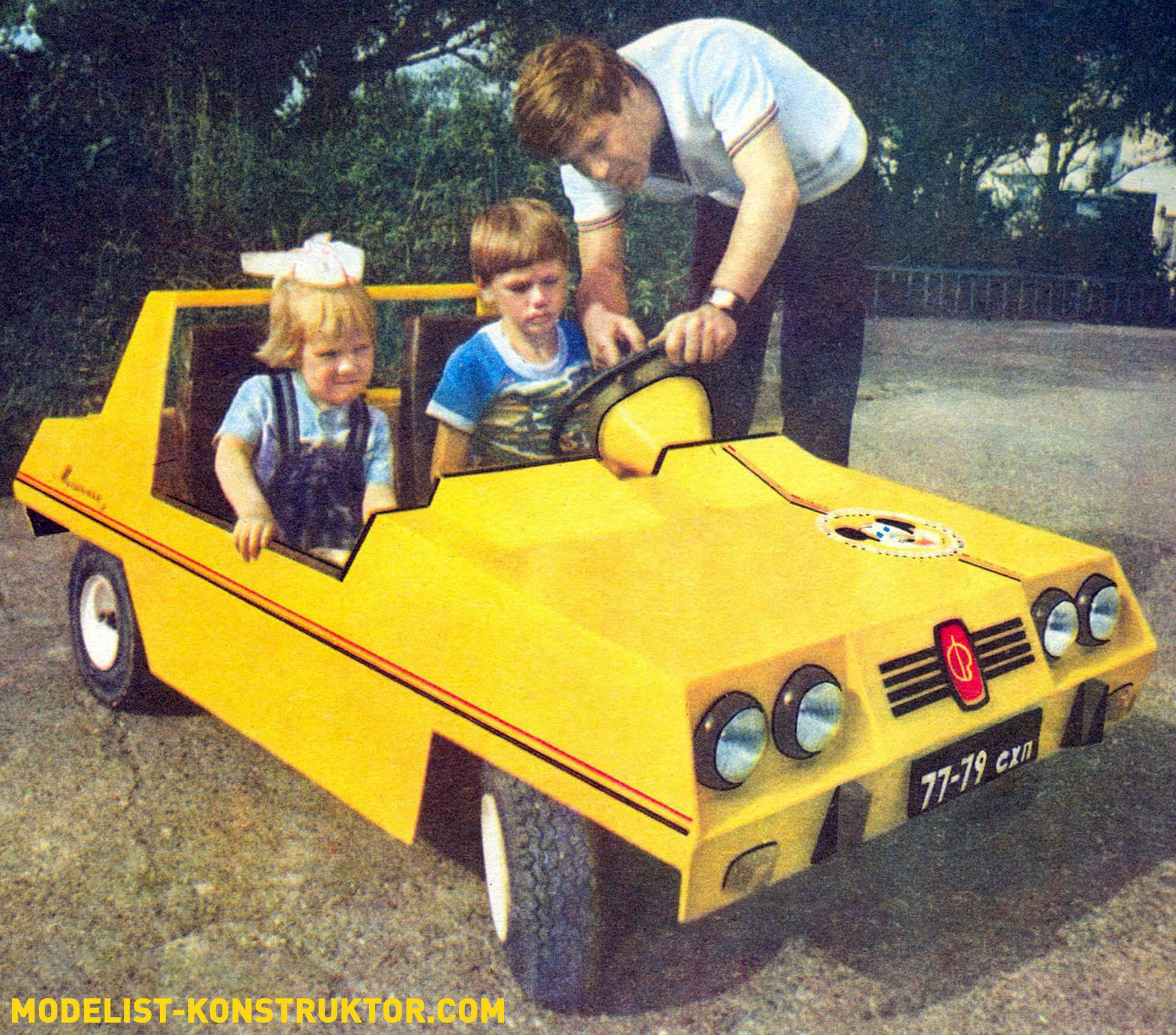
Flipping through the 1975 edition of Modelist, I noticed an article in No. 3 about the Cheburashka car, built by young technicians from Tbilisi. I liked the car and decided to make one for my kids.
But, taking the “Cheburashka” as a basis, I still had to assemble the little car in my own way (Fig. 1.2), based on my own capabilities and skills.
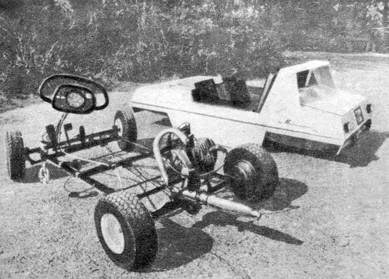
The frame of the two-seater car, called “Mouse”, was welded from thin-walled steel pipes. The front axle (Fig. 3) was assembled from a beam, two lugs and swivel units of the front wheels. The axles are axles fitted to the pivot bushing at an angle of 98° and welded to it. The rotary lever is curved from sheet steel 1.5 mm thick; it is attached to the pivot bushing by welding at an angle of 110°. The steering joint rings at the ends of the swing arms are cut from Ø12 mm steel pipe.
The pin bushings are equipped with bronze support liners, through which a pin is passed, which pivotally connects the bushing to the eye of the front axle.
Wheel hubs are steel, turned. Each contains two bearings (202 and 201), closed with seal washers.
The hub is fixed to the axle axis with a nut. A spacer is inserted between the bearings.
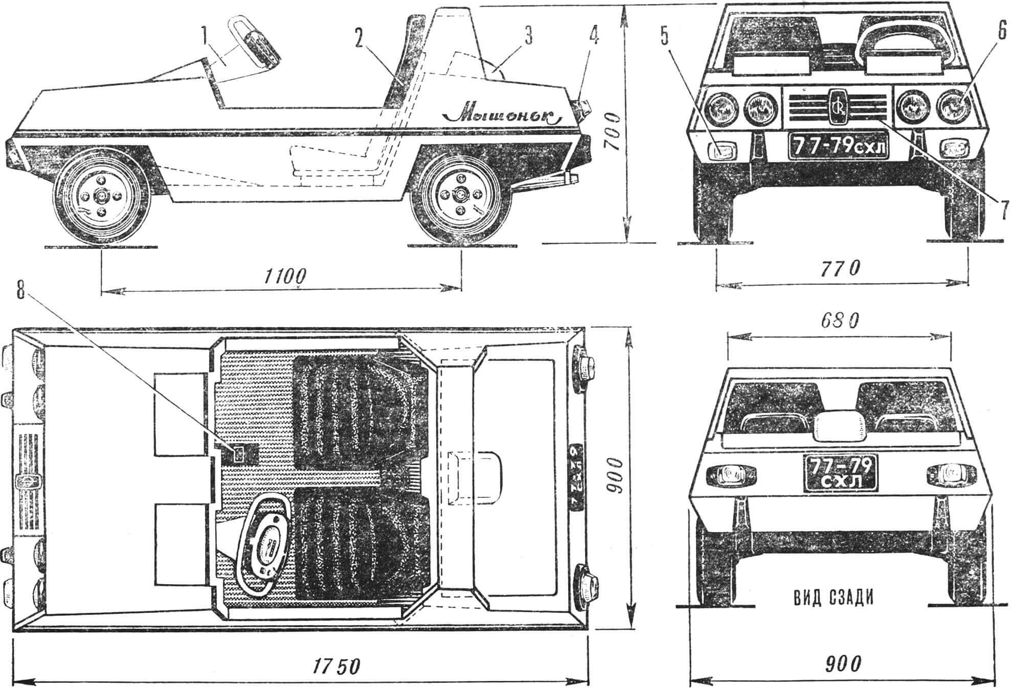
1 — steering bar, 2 — seat, 3 — air intake, 4 — lights, 5 — front flashers, 6 — headlights, 7 — decorative grille, 8 — control cable casing.
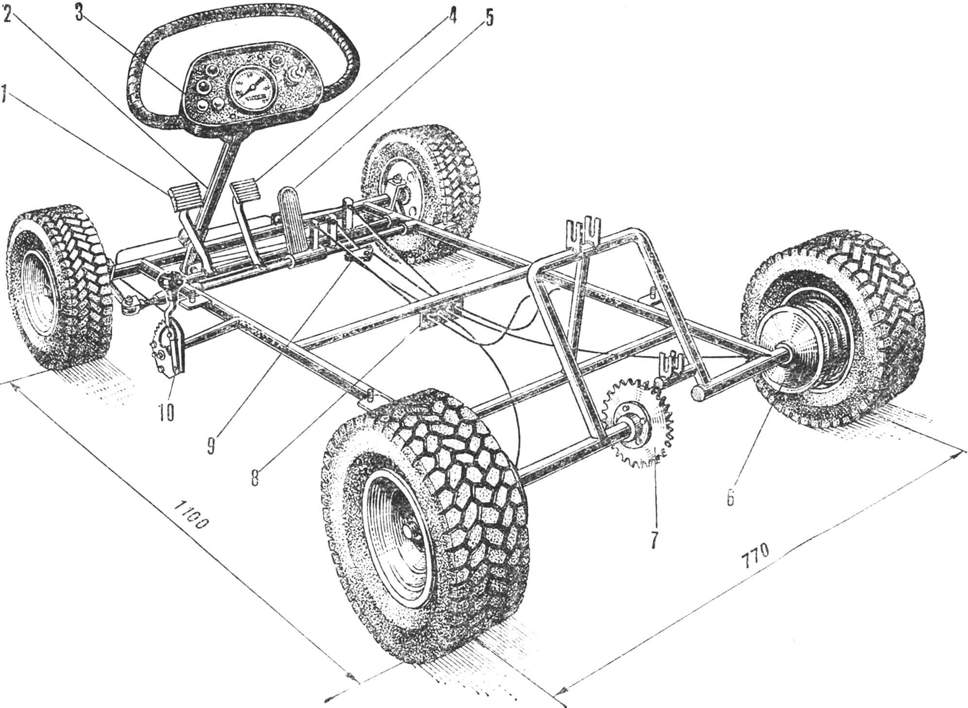
1 — clutch pedal, 2 — steering column, 3 — steering bar, 4 — brake pedal, 5 — carburetor throttle pedal, 6 — brake drum, 7 — sprocket, 8 — adjustable stops for control cables, 9 — differential brake drive drums, 10 — clutch pedal retainer.
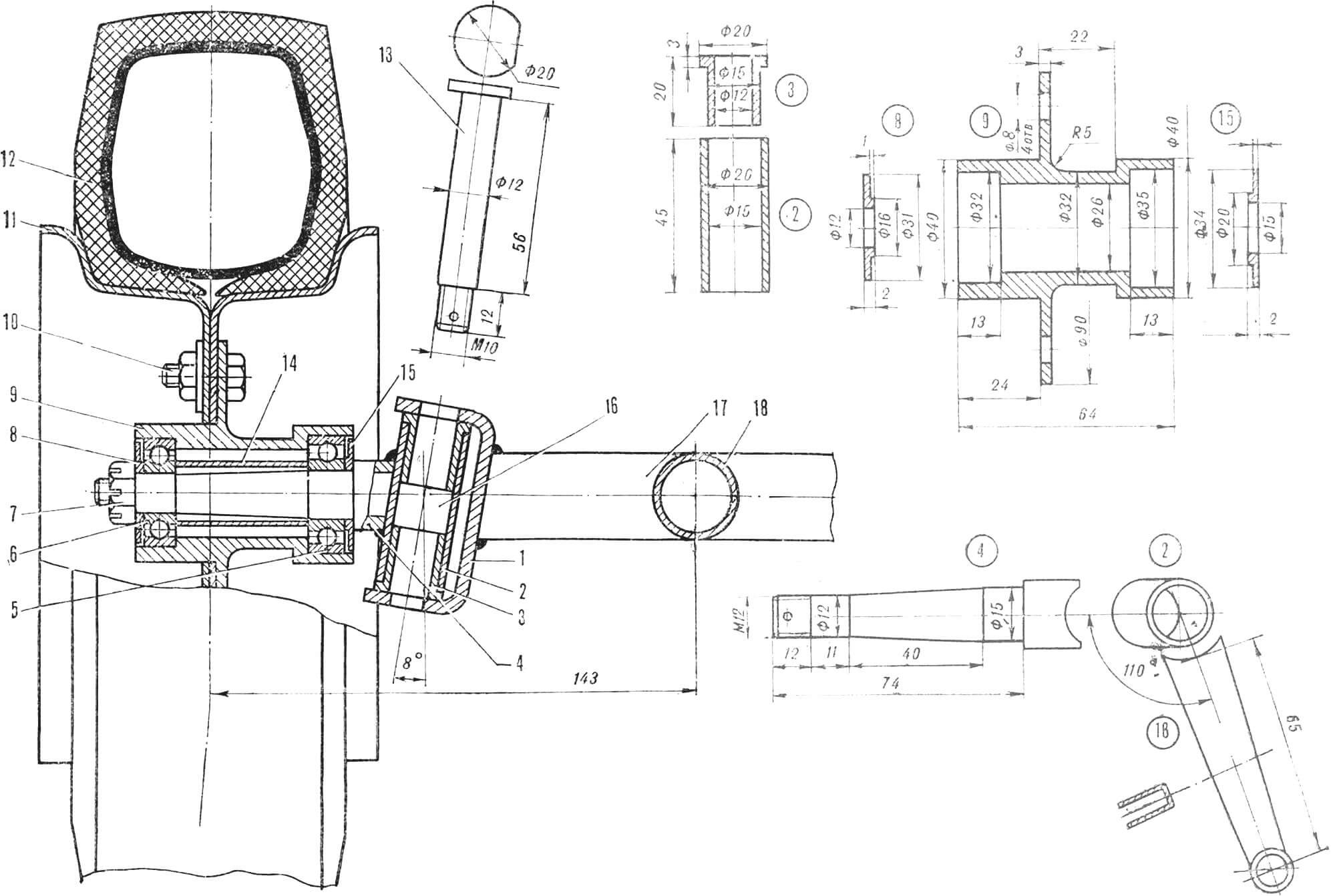
1 – eye, 2 – pivot bushing, 3 – support bushing, 4 – axle axis, 5 – bearing 202, 6 – bearing 201, 7 – M12 nut, 8, 15 – oil seal washers, 9 – wheel hub, 10 – M8 bolt , 11 — wheel disk, 12 — spike B-25 3.5X5.13, 13 — kingpin, 14 — spacer sleeve, 16 — swing arm, 17, 18 — frame beams.
Wheel disks are assembled from halves extruded from a steel sheet S = 1.5 mm on a lathe using a mandrel and a roller. (More details about this technology can be found in M-K No. 11, 1974.) To secure the disk to the hub, four bolts are head-welded to the hub.
The front axle lugs are connected to the beam at an angle of 98°, while the king pins are tilted back at 12°. The accuracy of setting angles during welding was ensured by the use of templates and spacers.
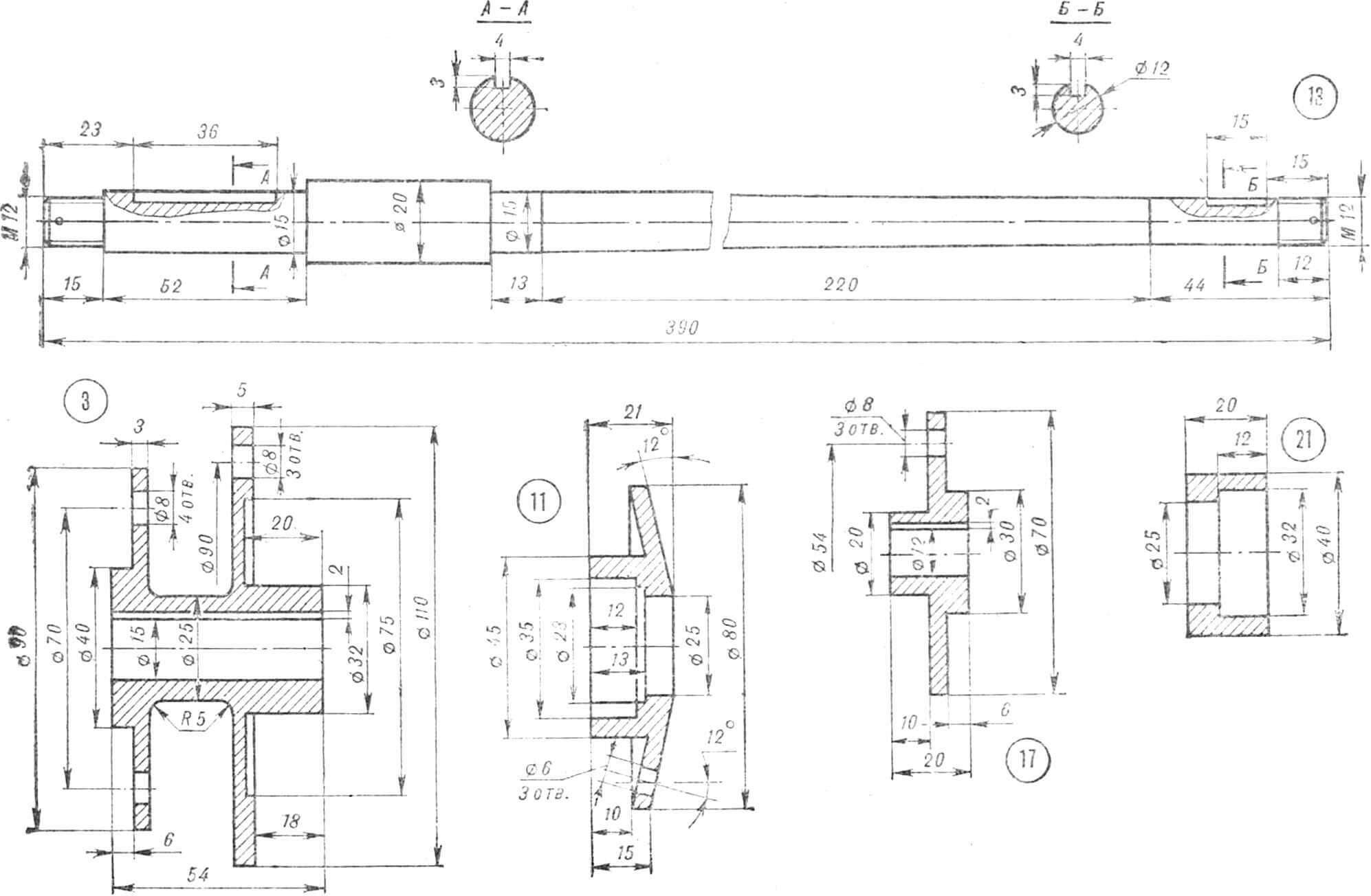
The rear axle is composed of a driving (Fig. 4) and driven (Fig. 5) half-axle. The basis of the first is a steel tubular beam, a bearing support is welded to it. The brake disc is attached to the support with three bolts. The axle shaft runs inside the half-bridge beam; the hub, machined from steel, is pressed onto the shank of the axle shaft, and in addition, it is secured with a key and a castle nut. The flange of the driven sprocket is pressed onto the opposite shank of the axle shaft and secured in the same way. The sprocket itself (Z = 30) is cut out of a steel sheet 3 mm thick and screwed to the flange with three bolts.
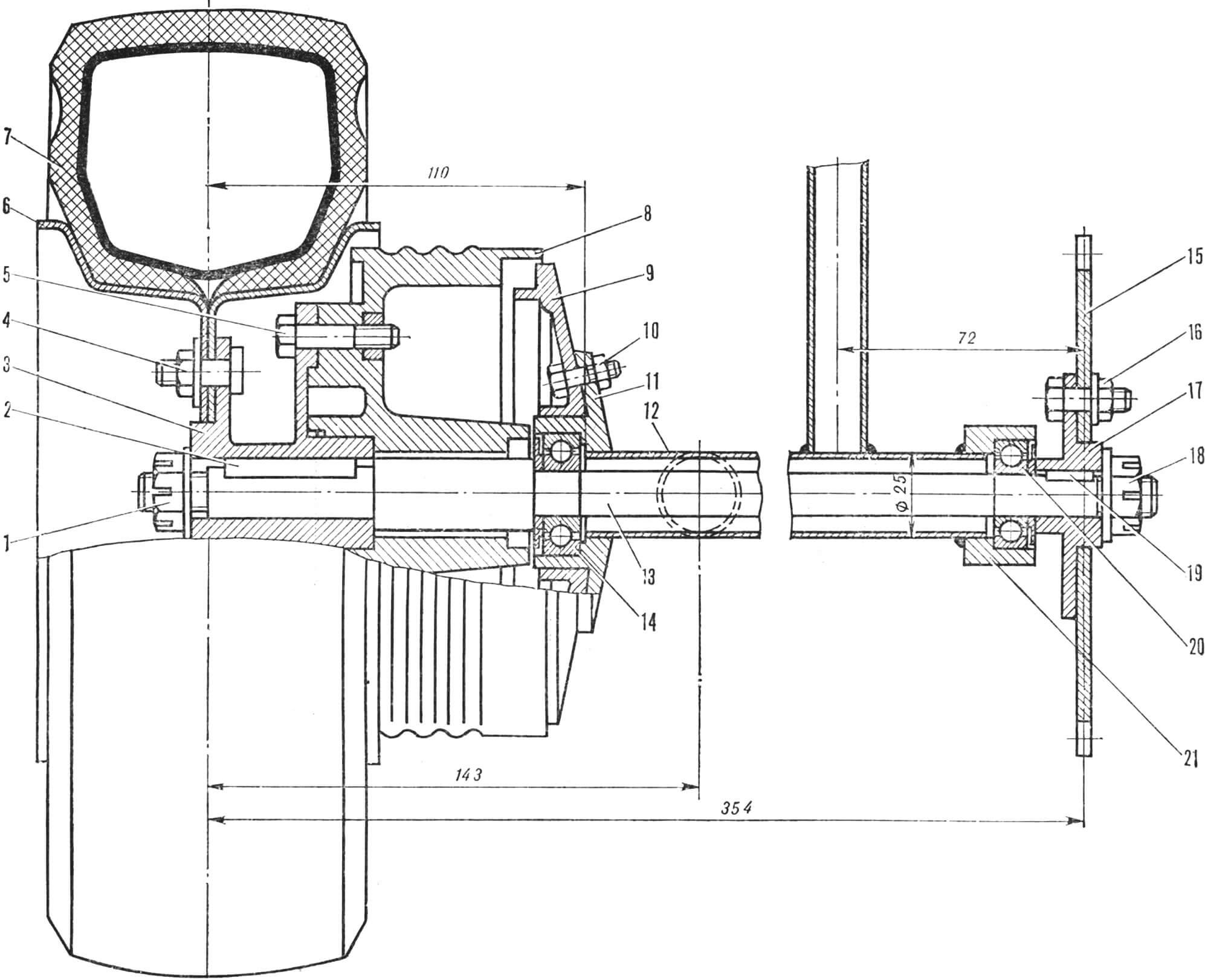
1 – M12 nut, 2 – key, 3 – hub, 4 – M8 bolt with cylindrical head, 5 – M8 bolt, 6 – wheel disk, 7 – B-28 3.5X5 tire, 8 – brake drum, 9 – brake support disk, 10 — M6 bolt, 11 — bearing support, 12 — half-bridge beam, 13 — drive axle shaft, 14 — bearing 202, 15 — driven sprocket (Z = 30), 16 — M6 bolt, 17 — flange, 18 — M12 nut , 19 — key, 20 — bearing 201, 21 — bearing support.
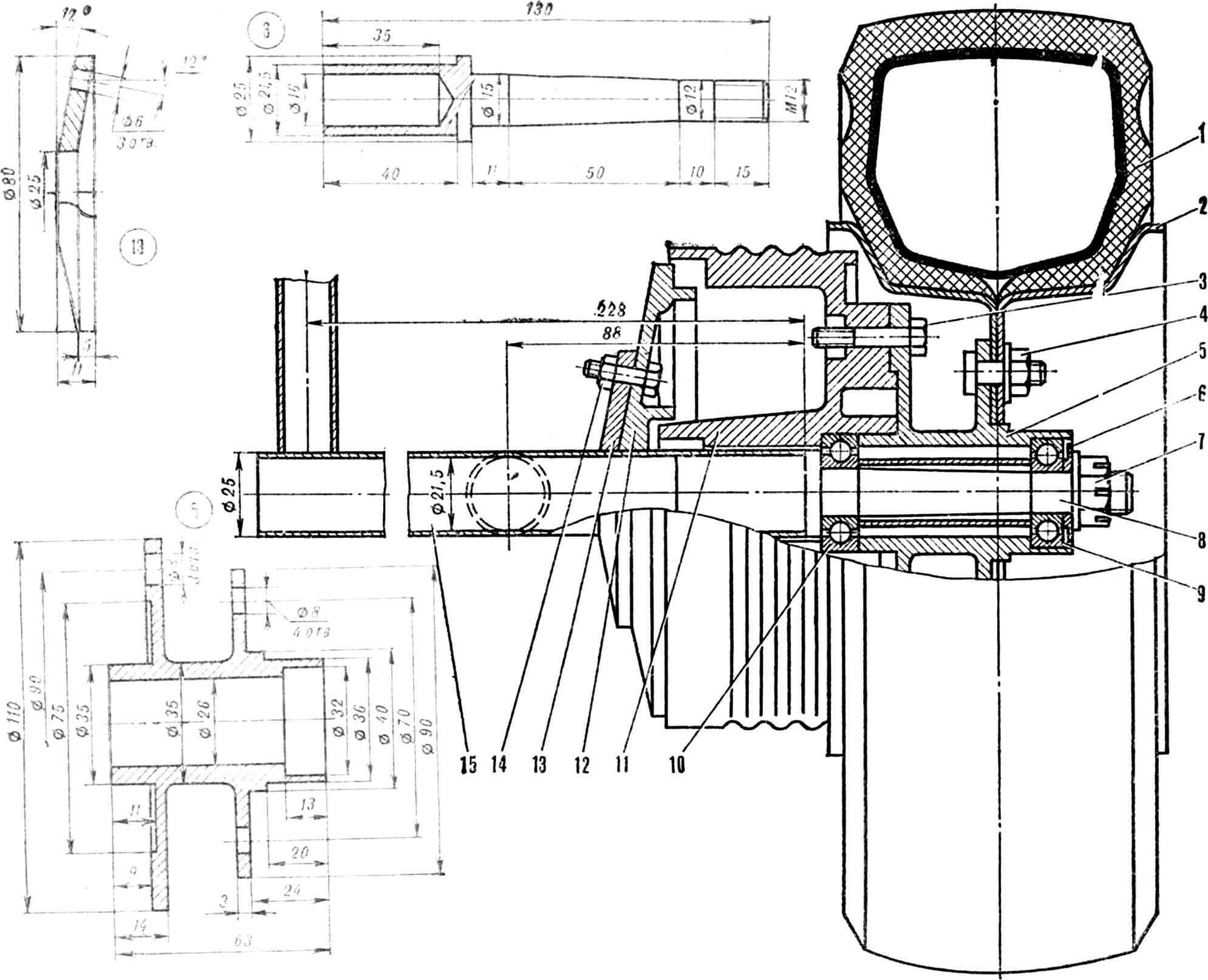
1 — tire V-28 3.5×5, 2 — wheel disk, 3 — M8 bolt, 4 — M8 bolt with cylindrical head, 5 — hub, 6 — oil seal washer, 7 — M12 nut, 8 — axle shaft, 9 — bearing 201, 10 — bearing 202, 11 — brake drum, 12 — brake disc support, 13 — brake disc mounting flange, 14 — M6 bolt, 15 — rear axle beam.
Driven (right) half-bridge. Its basis is a beam with a welded flange for attaching the brake disc. The latter is connected to the flange using three bolts. The wheel axle shaft is pressed into the half-bridge beam and secured with two through rivets. There are two bearings on the axle – 202 and 201, and bearing 202 is pressed with an outer ring into a pre-bored hole in the brake drum, and bearing 201 is pressed into the hole in the hub, which is connected to the brake drum with three bolts.
Engine “Mouse” from a motorbike, type D-5.
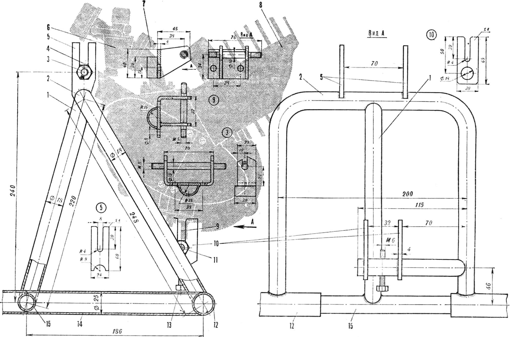
1 — front engine mount support, 2 — rear engine mount strut, 3 — M8 nut, 4 — front engine mounting bracket, 5 — front eye, 6 — K-346 carburetor, 7 — adapter pipe, 8 — D-5 engine, 9 — rear engine mounting bracket, 10 — rear eye, 11 — M8 nut, 12 — rear axle beam, 13 — M6 adjusting bolt, 14 — frame side member, 15 — rear frame cross member.
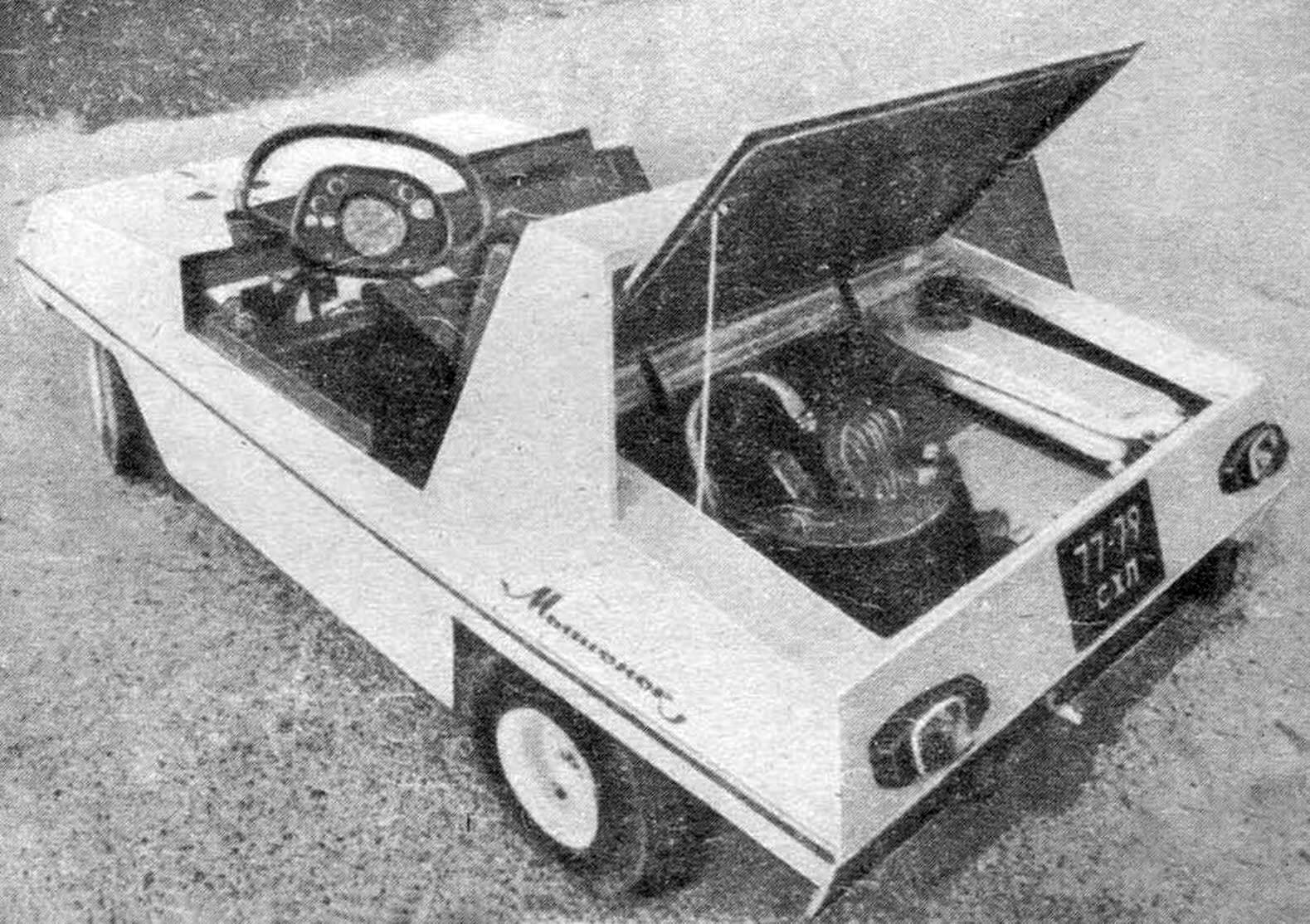
The motor frame (Fig. 6) for the engine is welded from steel pipes with an outer diameter of 18 mm. It consists of a front support and a rear pillar, to which are attached lugs cut from a steel sheet. Brackets are bolted to the standard engine mounting points. The chain tension is adjusted – with a bolt, it, resting against the bracket pin, moves the engine along the slots in the eyes in the vertical direction. The carburetor is connected to the engine by a transition pipe, since the engine is “flooded” backwards. The fuel tank with a capacity of 2 liters is located under the hood.
Steering (Fig. 7). Its main unit is a steering column with a steering bipod welded at the end, curved from a one and a half millimeter steel sheet. It is connected to the rotating arms of the front wheels by rods. The upper end of the column ends with a closed steering wheel (pipe Ø12 mm). There is also a steering bar with an instrument panel. The steering column rotates in two textolite bearings: the first is mounted on the front frame beam, and the second is mounted on the rack. Both are secured with steel plates. Longitudinal displacement is prevented by thrust rings.
To adjust the length of the tie rod, a threaded bushing is provided.
All steering joints have rubber bushings. The wheel rotation angle is 30°.
The clutch and brake pedals (Fig. 7) are made of steel pipes Ø12 mm. The pedal shafts are secured in textolite bearings mounted on the front cross member of the frame and side members. The gas pedal is a three-millimeter steel plate welded to the bushing. Its axis is the brake pedal shaft.
The control cables are motorcycle type, with adjustment by threaded stops. The brake drive cables are connected to the brake drums through a tension equalizer. The machine provides for the installation of additional pedals for the instructor, for which steel bushings are welded to the pedal shafts.
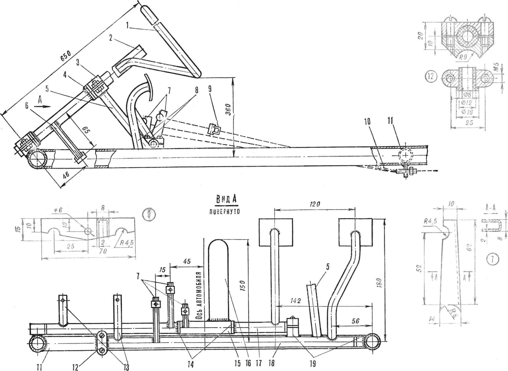
1 — steering wheel, 2 — steering column, 3 — bearing housing, 4 — thrust rings, 5 — steering column column, 6 — steering bipod, 7 — pedal levers, 8 — brake and clutch pedals, 9 — brake cable tension equalizer, 10 — adjusting stops, 11 — front frame cross member, 12, 19 — bearing housings, 13 — bushings for mounting backup pedals, 14 — rings, 15 — accelerator pedal bushing, 16 — accelerator pedal, 17 — brake pedal shaft, 18 — pedal shaft clutch.
The car body is wooden. I assembled it using glue and screws from 7 mm plywood (sheathing), two longitudinal slats and two frames. The outside was covered with fiberglass fabric on epoxy resin, followed by putty, primer and painting with nitro enamel. The front wheels were covered from the inside with mudguards made of sheet steel 1 mm thick. The seats were made from Ø15 mm pipes and plywood; the tops were covered with foam rubber and artificial leather. It even provided for adjusting the position of the seats depending on the height of the driver and passenger: longitudinal movement of the seats along the guides with fixation in the selected position with stoppers.
The car’s electrical appliances are powered by a battery assembled from twelve “373” elements, these include four headlights (from a bicycle), sidelights, direction indicators (motorcycle type), a brake light, and a sound signal.
The instrument panel, on which the speedometer, headlight and turn signal switches, horn button and warning lamps are mounted, is installed in the steering bar. The body of the latter is glued onto a papier-mâché blank with subsequent reinforcement of the surface with fiberglass.
The frame and body of the car are connected to each other by four threaded rods, so to dismember the car it is enough to unscrew the four wing nuts, disconnect the fuel line and the electrical connector.
In conclusion, I’ll add that I started working on the car in 1977 and finished it in 1979. The total time spent on construction (not counting turning work) is about 380 hours. It seems to me that the little car turned out to be durable, in any case, no troubles happened to it during the period of operation.
V. VESELOV, graphic designer, Kholmsk, Sakhalin region.
Recommend to read
 BUNDLE — STOOL
Who often have to deal with firewood for the stove or fireplace knows that tie the wood to carry from the woodpile home is not very convenient: the logs don't want to develop as it...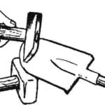 SHARPEN A HAMMER…
Working in the garden or in the garden with a blunt instrument — only a waste of time and effort. And to make the shovel or hoe sharp — requires grindstone. However, I succeeded without...
