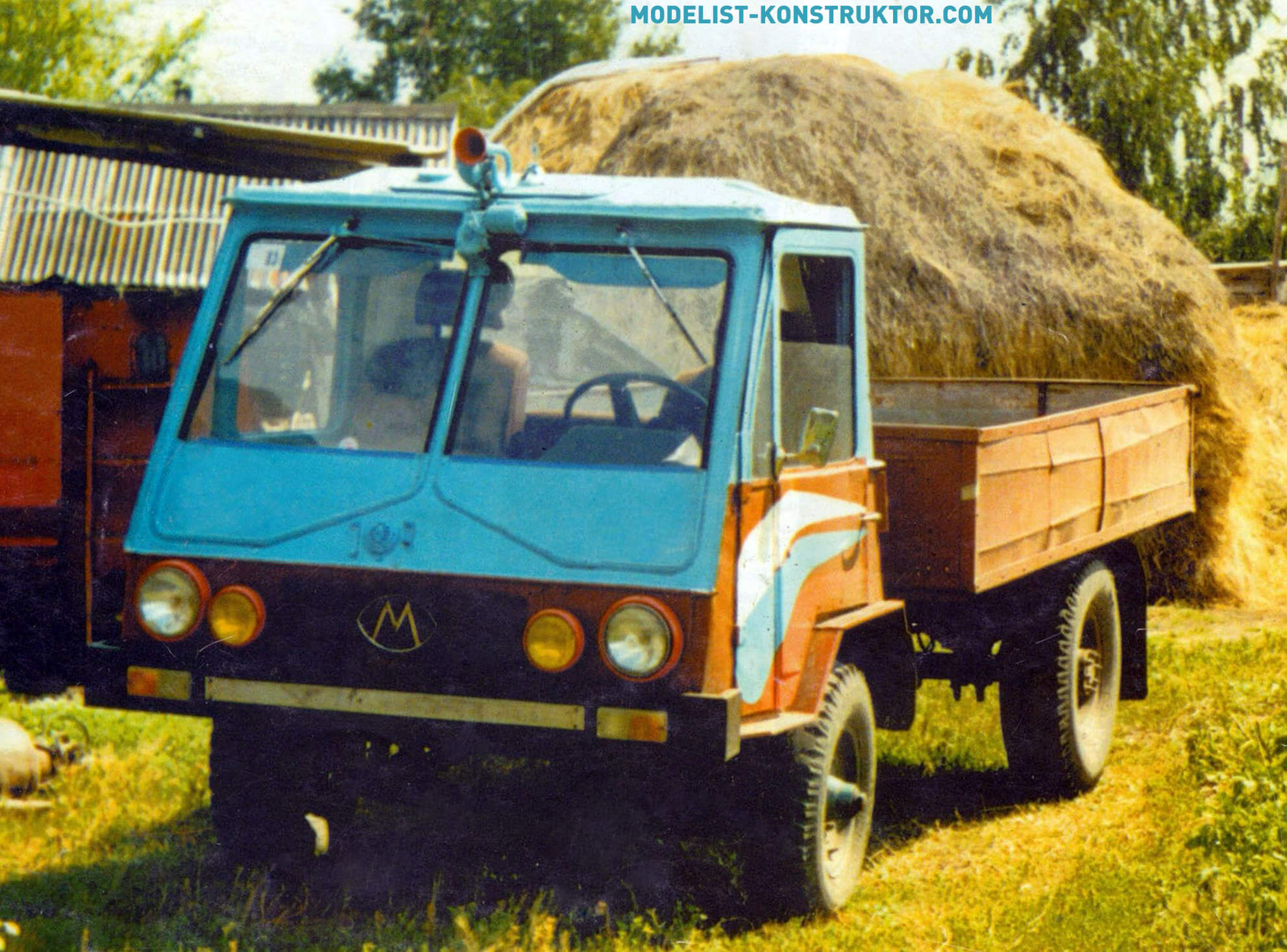
The car in question was created as a cargo vehicle to help survive in our difficult times.
My son and I made the car for almost a year. I would like to express my gratitude to the inspector of state technical supervision R.L. Markin. He is also an avid DIYer and has made many things with his own hands. And he helped us in word and deed.
I don’t consider the truck to be some kind of invention – it’s a successful arrangement of ready-made units with their partial modification for docking and joint work. True, I had to invent and do some things myself – for example, the gearbox control mechanism (Gearbox), located behind the engine, which, in turn, is located behind the cabin.
The truck is assembled from units of various vehicles and agricultural machinery, decommissioned and long-out-of-production, so to speak, “rudiments.” All units were previously repaired, most of them, in fact, were restored.
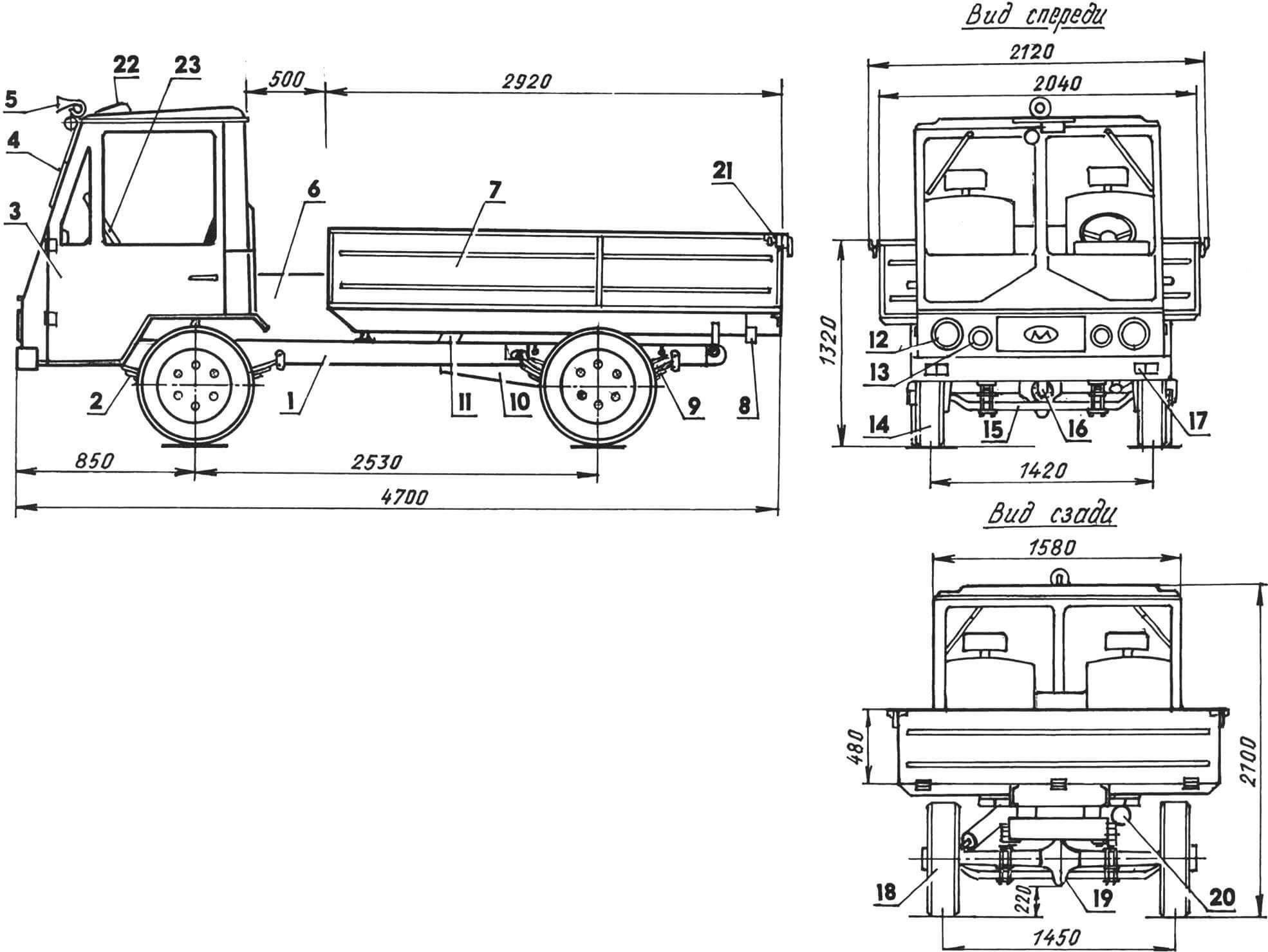
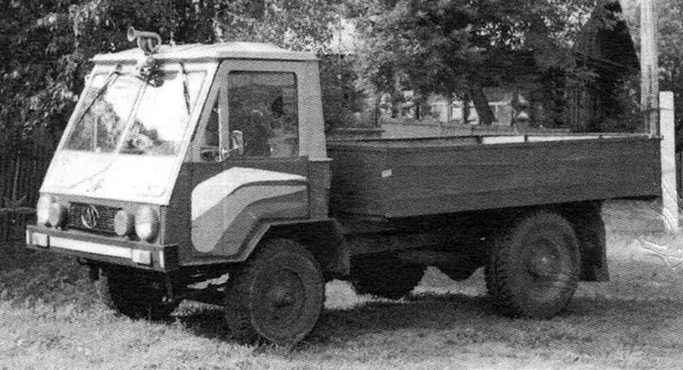
1 — frame (from a mobile reclamation pumping station); 2 — spring (front from GAZ-51.4 pcs.); 3 — cabin (from the T-150 tractor, modified); 4 — glass cleaning mechanism (from GAZ-51); 5 — horn signal (from GAZ-20 “Pobeda”); 6 — power unit (D-21A1 diesel engine from the T-16 self-propelled chassis); 7 — body (homemade); 8 — rear signal light (from VAZ-2101.2 pcs.); 9 — suspension (3 sheets from the rear spring of GAZ-51, 2 sets); 10 — muffler; 11 — body lift (from GAZ-SAZ-53B); 12 — headlight (from GAZ-51, 2 pcs.); 13 — fog lamp (2 pcs.); 14 — front wheel (from UAZ-469, 2 pcs.); 15 — front axle (from GAZ-51); 16 — cardan (from GAZ-51, shortened); 17 — front signal light (from VAZ-2101, 2 pcs.); 18 — rear wheel (from a tractor trolley, 2 pcs.); 19 — rear axle (from GAZ-51); 20 — reversing lamp; 21 — side body lock (from UAZ-452, 2 pcs.); 22 — hatch; 23 — steering wheel (from GAZ-24)
The result, although a little rough in execution (after all, it was manufactured not on an assembly line, but in a barn), was quite modern in appearance (or, as they say now, “in design”) truck.
The frame is from an old mobile pumping station for an irrigation system; it fits very well. Its spars and cross members are made of channel 100x46x4.5 mm. However, I regret that I did not use the frame from the GAZ-53 – it would not have required any special modifications either, but it has a softer suspension, and the springs are also attached through rubber cushions.
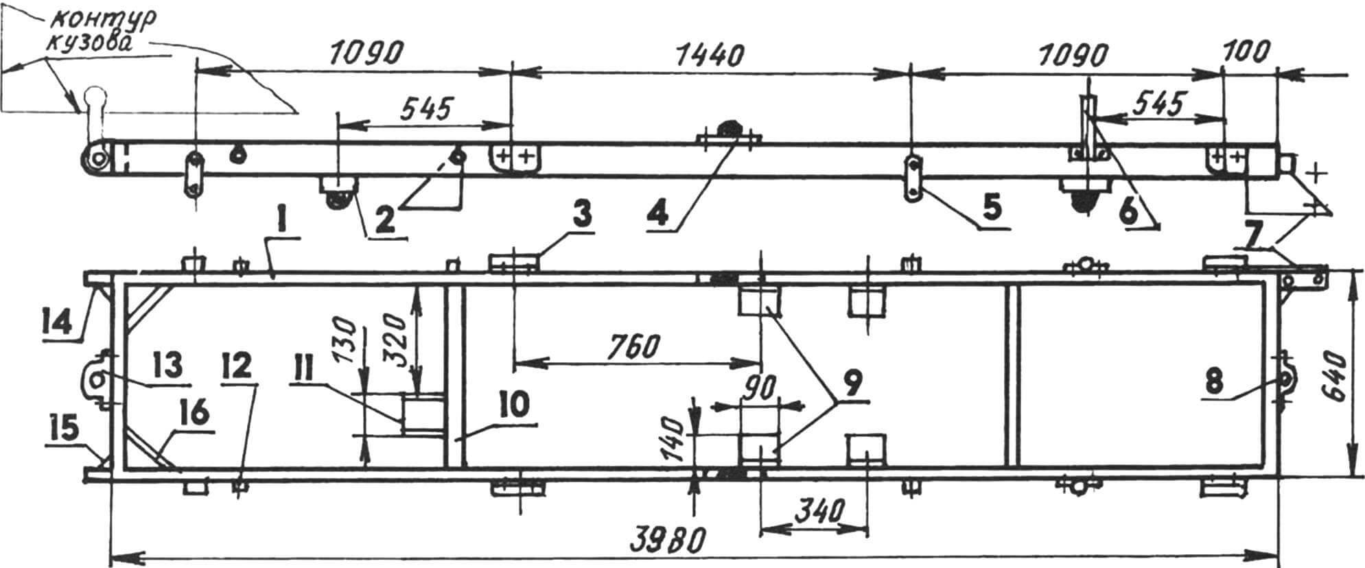
1 — spar (channel 100x46x4.5, 2 pcs.); 2 — travel limiter of the bridge beam (4 pcs.); 3 — spring bracket (4 pcs.); 4 — support cushion for the body frame (2 pcs.); 5 — spring earring (4 pcs.); 6 — shock absorber strut (2 pcs.); 7 — bracket for fastening the steering gear; 8 — towing eye; 9 — engine mounting brackets; 10 — crossbar (4 pcs.); 11 — stop of the telescopic body lift; 12 — travel limiter for suspension springs (4 pcs.); 13 — fork; 14 — bracket for fastening body hinges (2 pcs.); 15 — scarf (steel, sheet s5, 3 pcs.); 16 — strut (channel No. 6, 2 pcs.)
You can weld the frame yourself from the same channel or a larger number. It is important to determine its main dimensions. The width of the frame (my truck is 640 mm) is dictated by the steering angles of the front wheels and their diameter, the corresponding dimensions of the power unit and the width of the axles. The distance between the latter (base) determines the length of the frame (I have a base of 2430 mm). In turn, the base depends on the layout of the power unit and transmission.
Various brackets are welded or bolted to the frame, and holes are drilled for mounting all the necessary components and assemblies.
A bracket for mounting the steering gearbox is mounted on the left side member in front of the frame. At the rear, brackets with holes for hinge mounting of the body are welded to the ends of both side members; connections are reinforced with gussets.
A tow bar is welded to the rear cross member of the frame, and a towing bracket is welded to the front cross member. A thrust platform for the telescopic body lift is mounted on one of the intermediate crossbars. The brackets and spring mounting earrings are screwed to the side members with M10 bolts, and between them (from below to the channel flanges) there are steel cups of rubber limiters for their travel. For the front suspension, shock absorber struts are attached to each side member, and for the rear suspension, suspension travel limiters are attached. Two more glasses of rubber adjustable body stops are welded on top to the shelves of the side members channels in the middle part of the frame. Between the intermediate cross members, four brackets (two on each side) are attached to the side members for mounting the engine.
The cabin is three-seater, attached to the frame at four points through rubber cushions. Its basis is the cabin from the T-150 tractor. The frame, roof, doors were cut – adjusted to the required dimensions (based on my build) and thus lightened. The old floor was cut off and a new bottom was welded from a galvanized 1.3-mm steel sheet from the “keys” of the straw walker of a long-decommissioned combine harvester. The bottom is stepped, the rear part serves as a support for the seats.
The windows in the doors are roll-down. The windows do not turn, but the hatch on the cabin roof is retained and functional. The windshield is composite, equipped with two wipers. In cold weather, the inside is blown with warm air from the cabin heating system. There is no washer (for now I can do without it, since I have to drive mostly on country roads, alone, mostly in dry weather).
The dashboard is homemade, made of 1.5 mm steel sheet, covered with leatherette. On its left side there is an instrument panel from Moskvich-2141, on the right there is a “glove compartment”, in the middle there is audio equipment (but the latter, of course, is not at all necessary to install). I’ll replace the shield if necessary: it doesn’t matter when one device malfunctions, you have to pull everything out with the shield. It is advisable to do it like in a truck, where each device is on its own.
At first the seats were homemade: frames welded from corners, covered with fabric on foam rubber. But then they gave me a used Ford car as a gift. I mounted them around the edges and left a homemade one in the middle. A tool box was placed under it.
Inside the cabin I made soft upholstery on the ceiling, doors, and walls.
All control pedals are suspended, from a VAZ-2101 car, and the gear shift lever is also from it. The handbrake lever is from a ZAZ-968 (“Zaporozhets”) car. The steering wheel, ignition switch and the entire column are from a decommissioned GAZ-24 taxi. But the sound signal is a real rarity: from the GAZ-20 Pobeda car. I even installed it on the roof of the cabin. True, such a device is not the only one; there are also other components and assemblies – its contemporaries, who are unknown how they survived. For example, front and rear axles. Both of them are from the long-lived truck GAZ-51, a very common and good car for its time. And although they stopped producing it about 30 years ago, it was in production for just as long, so they made a lot of them.
The standard brake drums and wheels were removed from the rear axle, and instead they were replaced with products of the same name from the 4PTS tractor trailer. It has smaller sixteen-inch wheels and herringbone tire tread. Let the speed be lower, but there will be more traction and better maneuverability. Instead of paired wheels, there is only one wheel on the rear axle. New holes are drilled in their disks according to the location of six studs on the “lawn” flange of the axle shaft. But then I made a combined wheel: I took the disk from a GAZ car, and welded a rim from a trolley wheel to it.
On the front axle, I replaced the steering axles with hubs with similar parts from the rear axle of the SK-5 Niva combine harvester (they will also fit from the SK-6 Yenisei combine). After this modification, fifteen-inch wheels from a UAZ car were installed here. They are also combined: their rims are UAZ, and their wheels are combine ones. On the GAZ-51, the track of the front wheels passed between the twin rear wheels, but now the track almost coincides, which has a positive effect on cross-country ability. The steering is from a UAZ-452 car. Only to reduce the turning radius, the bipod was slightly extended in the forge, and the longitudinal link was shortened.
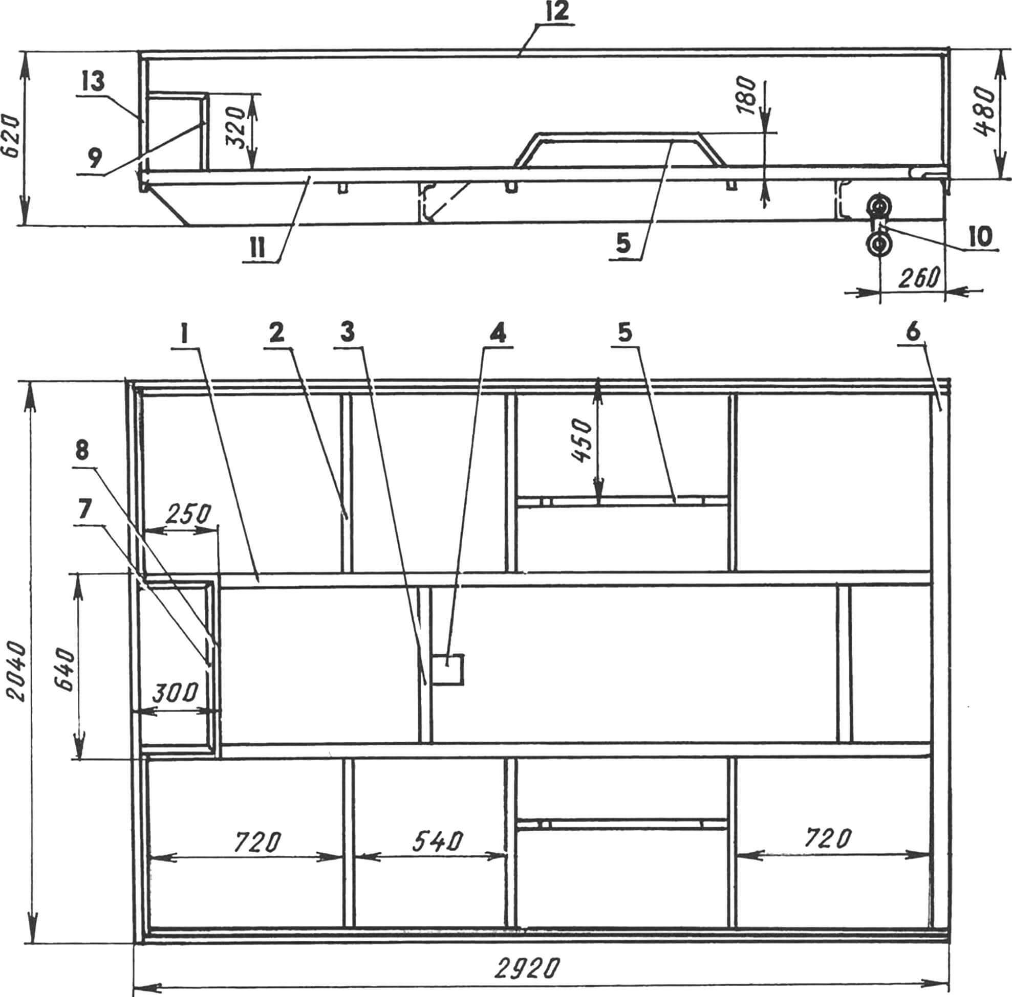
1 — spar (channel No. 14a, 2 pcs.); 2 — rib (square pipe 30×30, 6 pcs.); 3 — cross member (channel No. 14a, 2 pcs.); 4 — lift support bracket; 5 — wheel arch (angle 50×50, 2 pcs.); 6 — rear traverse (angle 80×80); 7 — upper frame of the engine niche (corner 30×30); 8 — lower frame of the engine niche (corner 50×50); 9 — engine niche stand (angle 30×30, 4 pcs.); 10 — body hinge bracket (connecting rod from the GAZ-51 engine, 2 pcs.); 11 — side edge of the side (corner 50×50, 2 pcs.); 12 — side edge reinforcement (angle 30×30, 3 pcs.); 13 — rack (corner 30×30, 4 pcs.)
The body is completely homemade. The basis of its frame is two spars and two cross members between them made of channel No. 14a (140x62x4.9 mm). The distance between the body frame side members is the same as between the frame side members. At the rear, a cantilever traverse from an 80×80 mm angle spanning the entire width of the body is welded to the ends of the side members.
The sides and bottom of the body are made of the same galvanized steel sheet as the cabin floor (from the combine straw walker), only 1.3 mm thick, so they had to be strengthened. Ribs are welded to the bottom, and racks made of 30×30 mm square pipe are welded to the sides. There are three niches in the underbody: one in front above the power unit, and two more on the sides – above the rear wheels. Niches, of course, “eat up” part of the useful volume of the body, and wheeled ones also make it difficult to unload bulk materials. But this body design reduces the loading height, which is more important in most cases.
All edges and ribs of the sides and niches are reinforced with steel profiles: at the bottom, the junction of the sides with the bottom is a 50×50 angle (from old beds), at the top and at the niches – a smaller angle: 30×30 mm and other suitable sizes.
Dump body. The hydraulic lift stop is attached to the first (front) cross member with M10 bolts, and hinge brackets (upper heads from GAZ-5 engine connecting rods), as well as U-shaped brackets for rubber mudguards and rear signal light blocks from VAZ-5 are welded to the side members at the rear. 2101. The rear side of the body folds down. Locks are from GAZ-51.
Well, now about the main thing – the power unit and transmission.
Engine D-21A1 – diesel, two-cylinder, four-stroke, air-cooled, 25 hp. (18.4 kW) with a maximum crankshaft speed of 1800 rpm. Such motors are found on the T-25 tractors of the Vladimir plant and the T-16 self-propelled chassis of the Kharkov plant. The standard starter was unable to start the engine in cold weather, so it was replaced with a starter from the T-40 tractor. I also installed a homemade air purifier with a dry cardboard filter element from a combine.
The engine is located behind the cabin. To do this, the distance between it and the body had to be kept quite significant – 500 mm. In addition, a small niche is made in the middle of the front part of the body, but free access to all engine and transmission components for maintenance and repair is provided. If necessary, you can further raise the body for this purpose.
The engine is combined with a gearbox from a GAZ-51 car through a clutch basket from a GAZ-53 (clutch discs are from a GAZ-52). At the same time, it was not possible to avoid alterations of some parts and assemblies of units for their mutual docking.
I disconnected the flywheel housing flange from the engine and machined a seat for the clutch basket in it on a lathe. The end flanges at the crankcase flange and the clutch basket casing were removed.
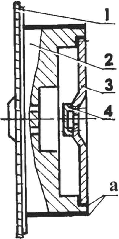
1 — flywheel crown D-21A1; 2 — flywheel housing D-21A1 (modified); 3 — GAZ-52 flywheel housing (modified); 4 — bearing housing 180203 (made according to the dimensions of the crankshaft flange of the GAZ-52 engine)
The engine flywheel also had to be modified, quite significantly. The “salt” of this alteration is that I connected two flywheels into one. To do this, the outer diameter of the engine flywheel (from the rear end to the crown) was machined to such a size that it fits freely into the clutch basket (let me remind you: it is from a GAZ-53 car). Next, the flywheel was machined from the inside so that another flywheel (without a crown and machined from the outside), taken together with the clutch from the GAZ-52, would fit into it. Previously, I installed bearing 180203 in a housing, which I machined to the shape of the crankshaft flange of the GAZ-52 car. I fastened both flywheels with three M10 bolts, having previously made the corresponding threaded holes.
Having connected the clutch to the combined flywheel, I hung them on an axle with a diameter of 17 mm and carried out static balancing (two years of operation did not reveal anything wrong). After this, the gearbox was docked to the clutch without modifications: the front end of its input shaft just reached the bearing in the flywheel.
Certain difficulties arose during the design and manufacture of the gear shift mechanism. After all, the gearbox (it’s from a GAZ-51) is located far from the lever, behind the cab and behind the engine. But, in the end, I solved this problem too.
The very principle of operation of the mechanism was borrowed from a self-propelled combine, but some components and parts had to be adjusted to fit the existing units. Firstly, I removed the cover assembly with the lever from another old gearbox from GAZ-51. I removed the two speed locks and gear shift forks from it. The switching rods (now they only serve as sliders) were lengthened on one side by 40 mm by butt-welding steel rods of the same diameter to them. Welding was carried out along “chamfers”, grinding the seams to the surface of the rods so that they would not interfere with the sliders moving in the lid sockets. I made flats at the ends of the extensions, between which I drilled a hole with a diameter of 8.2 mm. The bottom of the lid was closed with a bottom made of steel sheet and installed on the floor of the cabin.
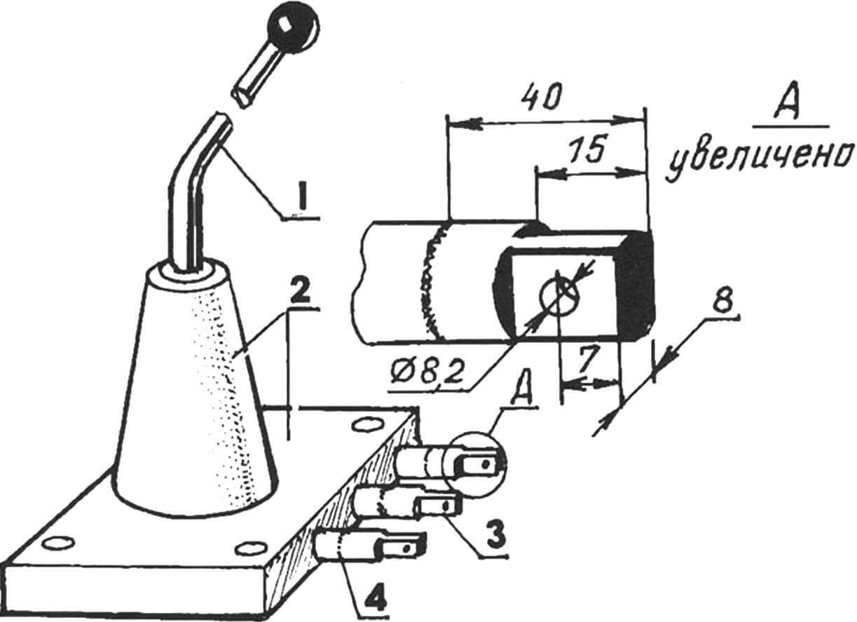
1 — swinging lever; 2 — cover with a tidal cone; 3 — elongated sliders with flats and holes for connecting rods; 4 – welding seam
The gearbox cover has also been redesigned. I cut off the cone from it and removed it along with the lever. In its place I welded a glass – a piece of square pipe 100×100 mm with a height of 150 mm. On the top side of the pipe I made a groove for installing a homemade gear shift mechanism into it.
The switching mechanism was not only original, but, in general, not so complicated and even compact. It consists of a central round rod and several pipes of various diameters and lengths, inserted into one another. During the design, only one condition was met: that the pipe in the pipe and on the rod sit freely, with a small gap (therefore, I do not give the dimensions of the mechanism parts in the drawing, but only give a diagram of its structure). A flange is attached to the rod at one end, and another pipe with the same flange welded to it is put on the outer pipe. The ends of each smaller diameter pipe (and rod) protrude from either side of the larger diameter pipe that is placed over it. Paired levers are welded to the protruding ends (on both sides), the free ends of which are cut along the same line.
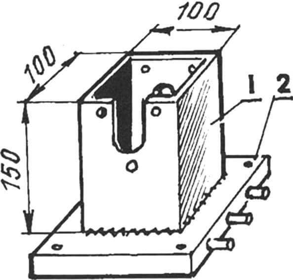
1 – glass (square pipe 100×100, L150); 2 — gearbox cover
Three levers (one side) are placed in a glass and their ends are inserted into sockets in the slides and fixed there with screws. The top of the glass is closed with a lid made of steel sheet (through a rubber gasket). The mechanism tubes are lubricated by splashes of oil from the gearbox. The other side of the mechanism was secured to the gearbox housing. The levers, through holes drilled in their ends, were connected to the ends of the rods.
Each rod has its own configuration, and quite intricate, since the rods were bent in place. Therefore, I present only a drawing revealing the design of the thrust.
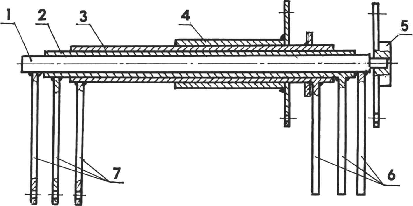
1 – central shaft-rod; 2 — middle shaft-bushing; 3 — outer shaft bushing; 4 – pipe with flange; 5 – flange; 6 — internal levers (3 pcs.); 7 — external levers (3 pcs.)
Since the rods are quite long, the gear changes were not very clear. I had to cut the rods and weld thinner intermediate rods into them, which I enclosed in bushing clamps, and mounted the latter on the engine mount stud, thus obtaining an additional intermediate support for each rod.
Two rods switch two speeds: one – first and second, the second – third and fourth, and the third rod – only rear. In order for the gear shift pattern to remain normal, the travel of the rods had to be made intersecting. By adjusting the length of the rods, I ensured clear gear shifting.
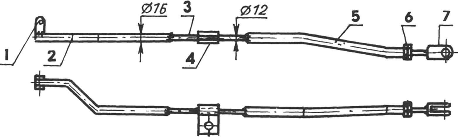
1 – eye for connecting to the gear shift lever slider; 2 — front part of the rod (pipe Ø16); 3 — insert (circle 2); 4 — clamp-bracket; 5 — rear part of the rod (pipe Ø16);
6 — nut with lock nut M10; 7 — fork-tip for connection to the outer lever of the gear shift mechanism
A small transfer case is mounted on the gearbox. With a minor finalization of the mating surfaces to the latter, the hydraulic pump NSh-10 is attached. It is used only to raise the body, and its power is enough. The pump is turned on with a lever along with a handout.
The telescopic lift is from the gas-SAZ-53B car. The lower end of the lift is connected to the emphasis located on the cross member of the truck frame, the upper end is connected – with an emphasis on the cross member of the body frame. The oil tank is from the receiver from the tractor trolley, located on the right side of the car under the body.
The fuel tank was first 60 liters. But where to get so much money right away to refue it completely? And he was very empty, clogging the system. Now it costs 27 liters (I do not spend more than 10 liters per day).
And the last is painting. I painted the car with oil paint, a brush. Of course, if there are funds, the finish can be done better. But even so, I pass the inspection without comments.
The own mass of the truck is 1800 kg, the carrying capacity – up to 2 tons. It can pull the trailer with a total mass of up to 3 tons. True, the engine in this case has to be hard, but it rarely happens to load the machine.
The truck can “run” up to 60 km/h and is not lagging behind the factory truck, but the permitted maximum speed is 50, and with a trailer – 40 km/h.
V. Mikhailov, p. Novopokrovka, Chelyabinsk region
Recommend to read
 THAN CLOSE THE GAP?
Often in the kitchen between a Desk and a sink or gas stove remain gaps. They fall poki matches, pot holders, fall into the water and garbage. In short they bring some inconvenience. To... MOBILE SERVING
In the everyday kitchen, as a rule, plays the role and a dining area for Breakfast and dinner, here, feed the children, because everything is at hand. But to sit at the table with a...
