ON ONE WHEEL

ON ONE WHEELHow many points of support should the aircar! Competition rules allow at least three. Earlier it was mostly given preference to such schemes to “extra” fourth wheel is not retarding the model. But someone came up with the idea to tear from track two. How to do it! It turns out, is only an extension of bar-spring rear track so that it turned into a wing. Yes, in the wing lift tail part of the body.

We present to your attention model is built on such a scheme. It is very simple to manufacture, and has repeatedly shown good results in competitions. An important advantage is the small distance between the axis of the screw and the ground — this reduces the influence of the diving moment from the thrust of the plant.
 
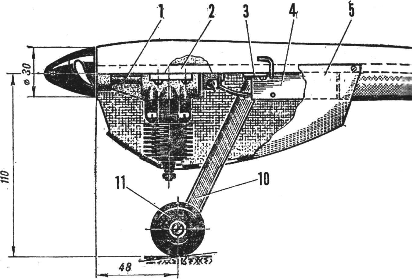
The FRAME of the aircar made of D16T sheet of 5 mm thickness. Accurately mark the workpiece (405X45 mm), cut out all specified in the drawing window and drill the holes, then treat its outer contour. Fit in place the engine decernite the centers of the holes for the screws, drill them with a drill bit Ø 2.5 mm and cut the thread M3.
 
The WING is a simple type of sheet duralumin with a thickness of 1 mm. Cut out the scan, will zakruglenie its front edge and taper the back. The resulting polished billet wing, drill in it, with the tail of the frame two holes Ø 2 mm for rivets. Now bend the plate: the ends will be the rear wheels. Rivet the fender to the frame. Don’t forget to saw through with a jigsaw, two shown in the drawing, slit, forming a kind of wheel height, which bending will be possible to achieve the optimum position of the body during a race.
 
FAIRINGS are of almost the same shape. The only difference is that the bottom breaks off in the tank. They are made like this: first frame is glued on both sides (BF-2) bars of foam stamps PS-1 (blank: 50X20X410 for the upper and 50X20X260 mm for the lower). After the glue has dried they are processed to obtain a predetermined shape. Do it better with a sharp knife with the subsequent finishing of the surface with sandpaper. Then the frame together with the foam glued fiberglass with a thickness of 0.1 mm, impregnated with epoxy resin are prepared. After curing of the resin the outer surface vyshkurivaetsya and arricivita. The nest under the engine crankcase can be cut with a knife and a chisel. Its inner surface is better also to paste over with fiberglass or just cover two or three coats of resin.
TANK volume of about 10 cm3 is made according to the scheme of single-chamber drinker. He is cut from a sheet thickness of 0.2—0.3 mm and is bent over a wooden mandrel. It will be nice if you contemplate on all seams flanging, which will increase the reliability and integrity of the soldering. All three copper piping — supply, drainage and gas (with an outer Ø 3 mm) is soldered into a finished tank. Please note that the holes in the legs of the attachment elongated tank. This gives you the opportunity, if necessary, to change the position of the tank relative to the axis futorki motor. Such adjustment may be necessary in order to ensure the sustainable operation of the engine throughout the race.
 
The slots in the legs of the tank in dural frame model corresponding holes drilled and tapped M3. They should be located so that when shifted to the left tank and right-edge was along the axis futorki.
 
The HOOD of the plant is laminated from five layers of glass, of a thickness of 0.1 mm. Pre-make a blank of wood or foam, and a separating layer to cover its surface may serve as the diluted PVA glue (3 layers). After waiting day after vyklicky, remove hood blanks and cut out the hole for the adjustment screw compression, the needle of the nozzle of the filling and drainage tubes of the tank. Now we have viscoret the surface and “fill up” the ends of the Windows for entry and exit of the cooling air engine. Six holes in the hood Ø 3,2 mm make threaded sockets in the ends of the frame under the mounting screws (M3 countersunk head).
 
Hood and body are best covered by road nitro, it quite well against all the components and additives of diesel fuel.
 
FRONT. Variants of its design a few, each has its advantages and disadvantages.
 
Hard front is made from strips of duralumin and privertyvaetsja three M4 screws to the frame of the model (the holes for them are drilled on the spot).
 
More complex version — with a spring shock. Here the steel tubular stand (30KHGSA, Т6Х1) upper end is clamped in the bracket (D16T, area 30X30) with two M4 screws. It propylene the groove under the font, to prevent rotation of the rod rack. The very core of wire OVS Ø 4 mm, the pin of the same material, only 1,5 mm. Ø the Main task of the Modeler to choose the spring stiffness of the shock absorber. It depends on how stable the aircar will “hold” for the track, not raising his nose or the tail and not flying up in the air.
 
Model of high-speed aircar with a propeller
 
Model of high-speed aircar with a propeller:
 
1 — the engine KMD-2,5, 2 — frame, 3 — cord strap, 4 — fuel tank 5 — bonnet 6 — upper fairing 7 lower fairing 8 — wing, 9 — rear wheel 10 — front 11 — rear wheel.

 
The most attractive, we think, and provides reliable route the coating of any quality option — stand manufacture minimum stiffness. It bends wire grade optical fiber Ø 1,5 mm in the form of a plug having feathers on both scrolling elements — springs. It is necessary to choose the outer diameter and number of turns so that put in the horizontal position of the model between the air screw and the ground remained a gap of 15-20 mm, and even at a weak pressing ka case the model must descend. The minimum rigidity of the rack will ensure a completely smooth “continuous” movement of the aircar, while the wheel will “beat” all the bumps in the track. Even when hitting at a considerable elevation force of the shock absorber is not enough to flip the hull and the model will pass, almost “not noticing” it.
 
ENGINE KMD-2,5. After checking its technical condition, do some revision. Basically it boils down to shortening futorki carb and reaming the Central hole up to Ø 4.3 mm. it is Possible to Refine the bypass channels in the sleeve, however, such work is best done under the guidance of an experienced modeller.
 
AIR SCREW – palm, exactly the same as on the snowmobile, which we described in number 10 “M-K” for 1980. If you prefer a two-blade, that can be mounted on the engine and its. Saw off the screw from beech wood (Ø 180 mm, and 190 mm).
CORD STRAP conventional type cut sheet of aluminum with a thickness of 2 mm. Fixed to the center of gravity of the model with two screws M2,5.
 
WHEELS are ready from toys. In addition to ease of elaboration, they offer another advantage — low weight. But refinement is only in the bonding of copper tubes-bearings. The rear wheels of a smaller diameter, because they are only at the start.
 
The model can be transformed into a snowmobile. For this you will need to remove the rear wheels (the”ears” of the wing will be ice-skating) and replace the front drop on the plate, made of D16T material and riveted between two sheets of PTFE. As you know, this plastic has the lowest coefficient of friction on snow and ice. Its use will help the model become even faster.
 
N. MOSQUITOES

Recommend to read

  • POWER SUPPLY WITH ACTIVE FILTERSPOWER SUPPLY WITH ACTIVE FILTERS
    For portable electronic equipment need a small volume and weight of the power supply. To solve this problem relatively simply by replacing passive LC and active RC filters.   The...
  • SHIELD FROM LIGHTNINGSHIELD FROM LIGHTNING
    Building a country house, we try to protect it from the damaging effects of fire: use heat-resistant materials, buy fire extinguishers, installed fire alarm. But the protection from...