By the time of writing these lines, I had built five catamarans of various designs. My friend Anatoly Pavlovich Ignatchenko took an active part in the design, construction and testing of these watercraft.
This is not to say that none of them satisfied me. The catamaran with inflatable floats performed well both on the reservoirs of the Moscow region and on the Lower Volga. But the pneumatics did not hold their shape well, which significantly reduced the speed. Therefore, the idea arose to build a catamaran with rigid floats.
Wooden floats, despite their ease of execution, were rejected. Water and wood, including plywood, are incompatible. But ensuring normal impregnation of wooden parts in a home workshop is not so easy.
Making fiberglass floats is tempting, modern, but difficult. In addition, when manufacturing fiberglass products, respiratory protection, protective clothing and good ventilation are required.
Rigid aluminum alloys, for example D16, hold their shape well when making float linings, but the sheets break when bent without heating. Therefore, I opted for sheets made from the more ductile alloys AMG and AD31, which bend well. As practice has shown, the choice was made correctly.
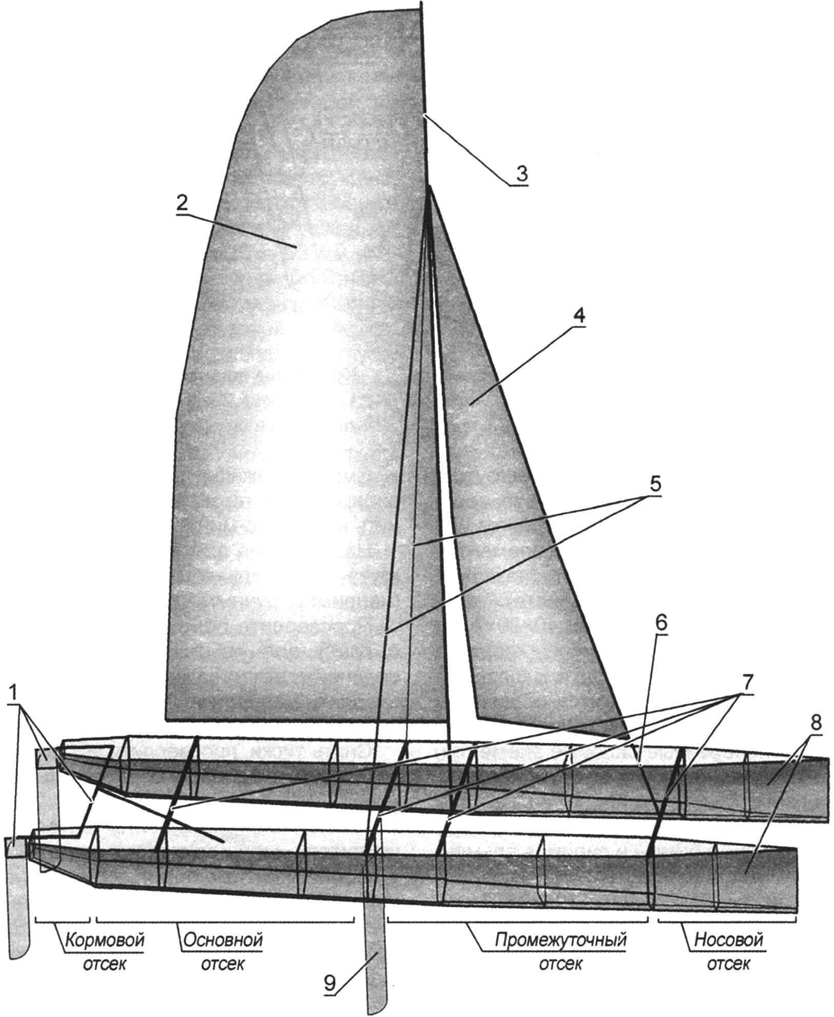
1 — steering device; 2 – grotto; 3 — mast; 4 — staysail; 5 — shrouds; 6 – forestay; 7 – beams; 8 — floats; 9 — centerboard;
The manufacturing process of the catamaran was carried out in stages: design, preparation of materials, production of floats, steering and centerboard devices, mast and sails, standing and running rigging, assembly and sea trials.
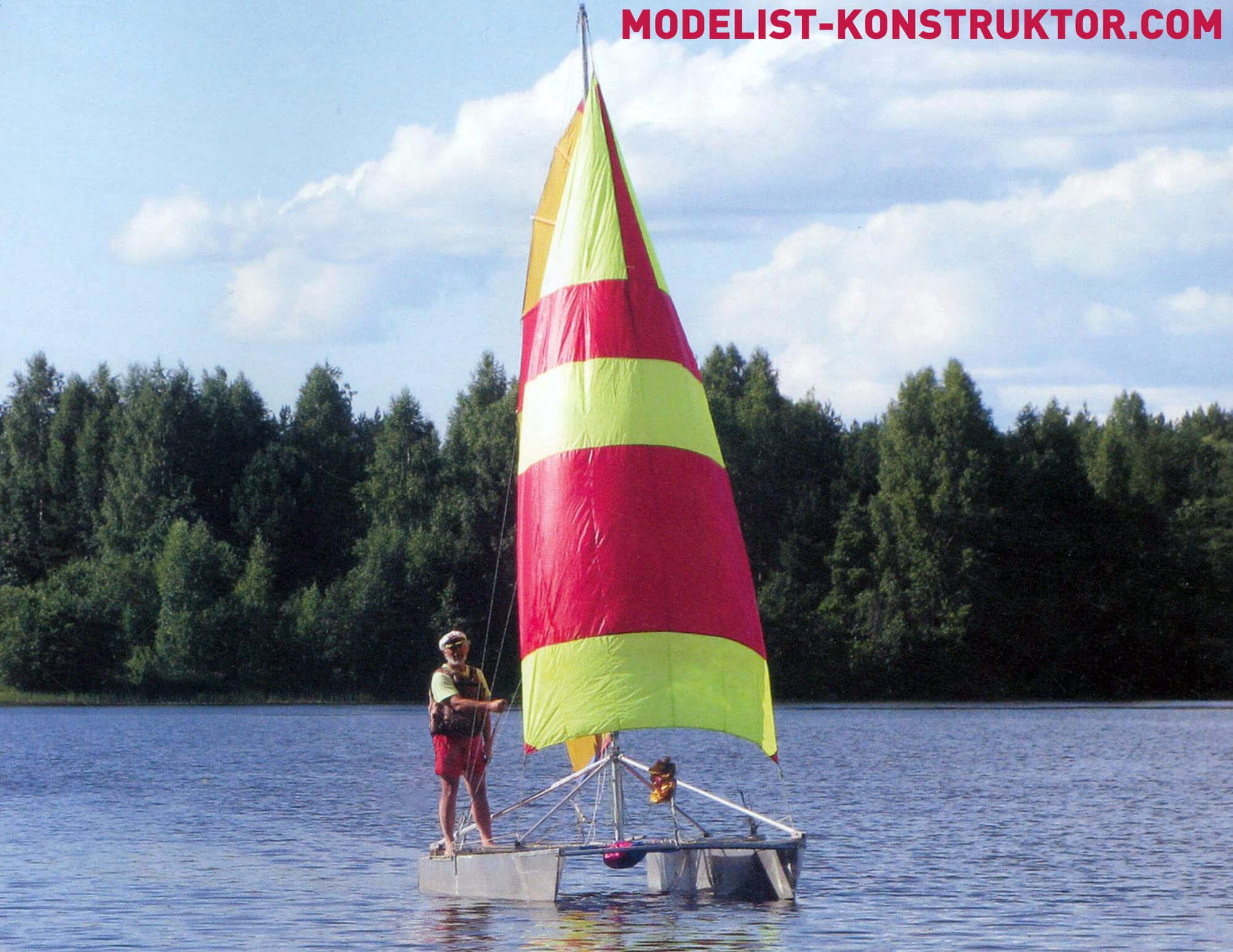
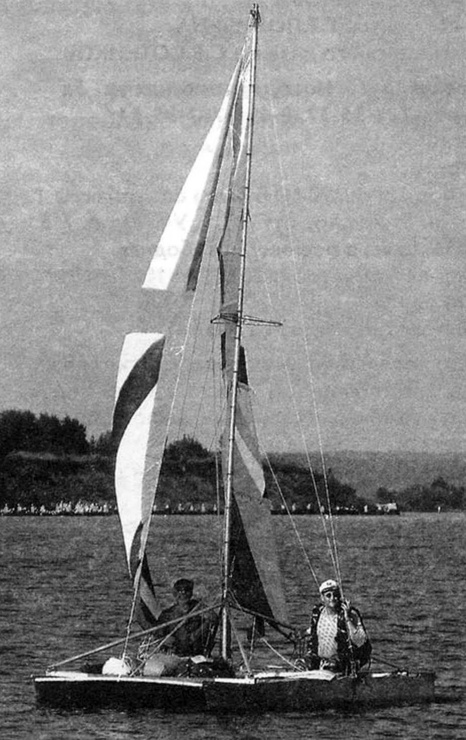
The design began by clarifying the purpose and dimensions of the vessel. The catamaran (later called “Rezviy”) was supposed to be used for day trips along rivers and lakes near the shores with 2 – 3 passengers at low speeds. I would like to note that it is not recommended to use a pleasure catamaran when the wind is more than 6 m/s and the wave is higher than 0.5 m.
For novice shipbuilders, even before starting design, it is advisable to study existing similar watercraft, paying attention to the positive aspects and disadvantages. If possible, ask for advice from experienced sailboat builders in order to avoid repeating their mistakes in your design.
Drawings of the catamaran were made using the AutoCAD computer program. But he made sketches for many elements and even individual assemblies. As practice shows, it is better to draw each detail on a roll of whatman paper on a scale of 1:1, reducing only the length of the longitudinal elements by cutting them out.
To avoid mistakes in building a catamaran, it would be a good idea to make a 1:5 scale model of it from cardboard and wood – it will allow you to understand the purpose of each element, check the accuracy of the drawings and determine the assembly order. After impregnation, the prototype can be launched into the water for testing.
When the catamaran project was ready, my friends conducted a study of the strength characteristics of the main structural elements, which showed their reliability.
DESIGN
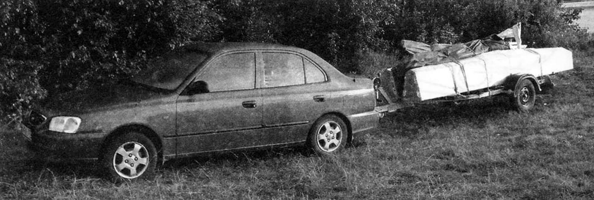
Floats. From the very beginning it was assumed that the catamaran would be dismountable for transportation on a trailer. In addition, in order to simplify the process of manufacturing floats and ensure high survivability and unsinkability of the catamaran, each float was designed as a composite of several compartments connected by bolts and filled with foam plastic.
The float deck is flat, made of AMG2 corrugated sheet 2 mm thick. I attached the deck elements (one for each compartment) to the upper stringers using rubber gaskets.
Beams. The floats of the catamaran are connected by four transverse beams – beams. The sub-mast beam is equipped with a device that counteracts its deflection from the pressure of the mast when the cables are tensioned.
1 — centerboard beam; 2 — centerboard fastening bracket; 3 – mounting area for stoppers fixing the centerboard in the working or raised position
The steering device is paired – consists of two feathers, the tillers from them are connected by a transverse rod, to the middle of which an extension handle is attached.
The centerboard is placed between the floats and is installed in the working position (lowered vertically into the water) under its own weight. It is secured against longitudinal and transverse movements by pairs of rods (transverse ones with lanyards).
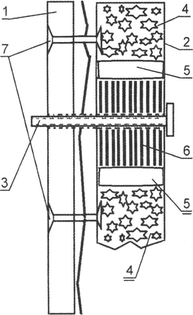
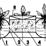
1 — frame; 2 – stringer; 3 – bolt; 4 – foam plastic; 5 – sealant; 6 – amplifier; 7 – blind rivets
The mast consists of three legs connected by diamond shanks. It is placed on the submast beam through the heel and steps and secured with a forestay and three pairs of shrouds. Standing rigging is made of stainless steel cable with a diameter of 5 mm. By using a special mast profile, rigging can be simplified. But it is better to increase the strength of the rigging (accepting the increase in mass) than to break the mast at the most inopportune moment.
Sailing rig: Bermuda sloop. The mainsail with a large sickle is equipped with six through armor. The staysail is furled onto the forestay. The running rigging is made of nylon rope; cam stoppers are used for fixation.
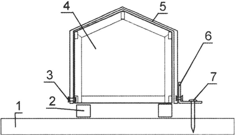
Tent-decks. To accommodate passengers and crew, an awning is stretched between the centerboard and stern beams, and the cargo is placed on the awning between the front and podmast beams. Awnings are made of durable synthetic fabric or a special awning mesh. The disadvantage of the fabric is that when water gets on the awning, it does not completely drain, but at the same time, splashes from the floats do not fall on the cargo and crew.
MANUFACTURING CATAMARAN ELEMENTS
If the construction of a catamaran is planned during the cold season, the room must be heated. The dimensions of the workshop, at a minimum, should allow the entire length of the float to be assembled. Of course, it is not possible to install the mast in the working position (vertically) on a catamaran in every room. But assembling it completely, without installation, is simply necessary. In addition, the mainsail can be fine-tuned on the assembled mast. Thus, the length of the room should be 8 m and the width at least 3 m.
1 — frames; 2 — stringers; 3 – keel; 4 — braces-kerchiefs; 5 – casing
To assemble the power set of catamaran float sections and then cover them with metal, I prepared a chipboard sheet with dimensions of 1830x2440x25 mm, two edged boards (linings) 40 mm thick, 2200 mm long and at least 100 mm wide. A slipway was made from these elements. I placed the drawings on the wall near the slipway. Using felt-tip pens of different colors, I applied markings to the surface of the chipboard that corresponded to the position of the frames and stringers of the floats. Boards (overlays) are installed on the stringer line and secured to the chipboard with screws. To fix the frames in a vertical plane, struts are made from plywood, sheet metal and “corner” scraps.
As a long ruler, you can use pieces of boxing (as the factory price list indicates a pipe made of AD31 alloy with a rectangular section of 40x20x2 mm), from which the stringers are made.
I first made the drawings on the chipboard (slipway).
Particular attention had to be paid to the process of assembling individual elements of the catamaran. It would be a good idea to write down the order in which each part is put into place. This is where the layout comes in handy. If after assembling the structure there are any parts left, you need to go back so that this does not happen again on the real structure. On a mockup, errors are easy to correct, but on a real design, an error will lead, at best, to additional costs of time, materials and money, and at worst, to a decrease in strength, breakdowns during operation, etc.
When manufacturing the structural elements of the catamaran, he did without welding, using only “bucket” rivets, screws and bolts with nuts to connect parts. Some elements were fastened with pins. In addition, foam blocks were placed in each section of the floats to ensure unsinkability.
It is advisable to fill hollow parts made from boxing (stringers, frame reinforcements) with foam and reinforce the holes in them, where other elements will be connected with metal plates of suitable size.
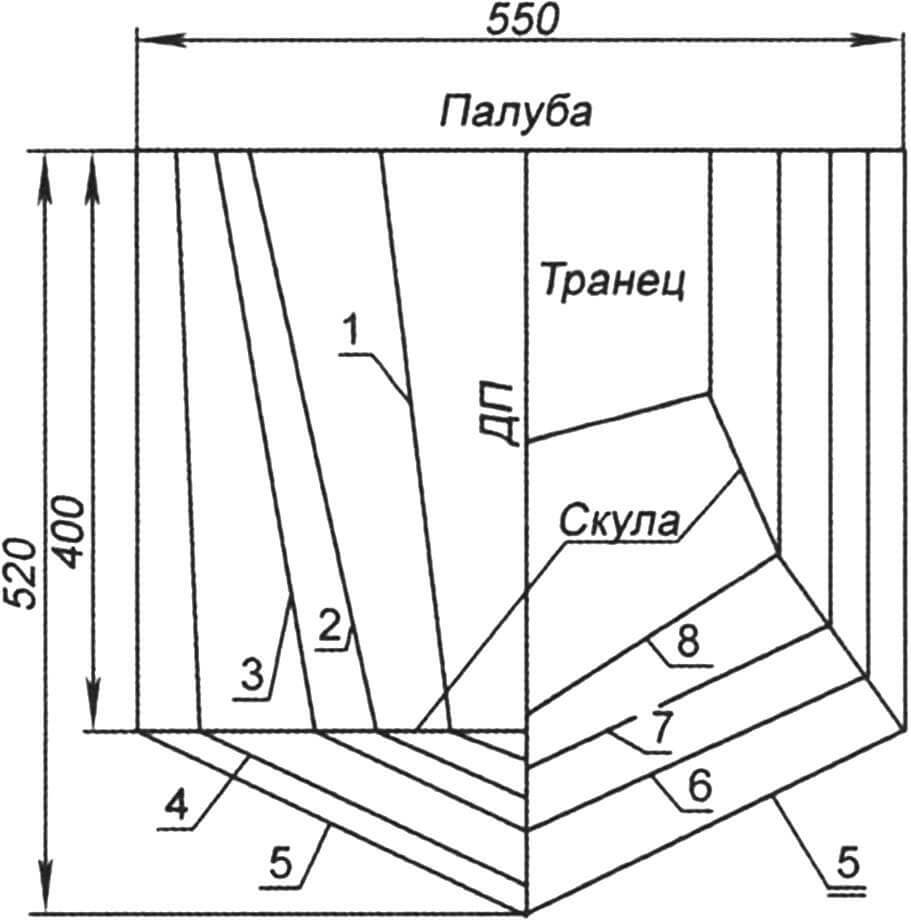
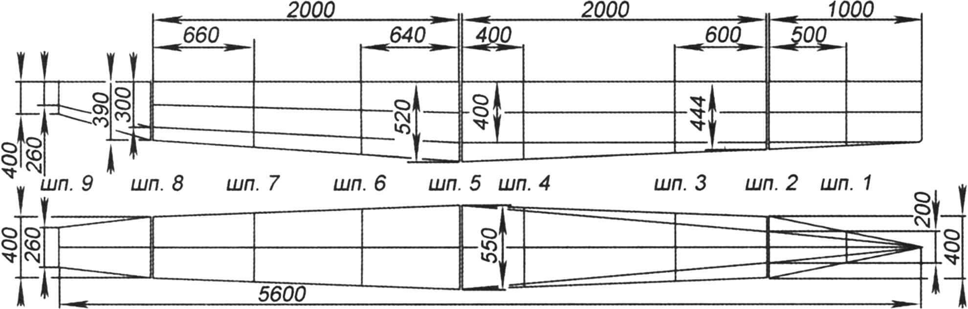
The catamaran floats are interchangeable. As already mentioned, the float consists of four compartments – bow, intermediate, main and stern. The division of the middle compartments of the float into “intermediate” and “main” is conventionally accepted, for the convenience of talking about the design. A submast beam is attached to the intermediate compartments of the float, the shrouds and forestay are fixed, and a cargo awning is stretched between them. The main compartments, or rather the tent-deck, accommodate the crew between them.
The power set of each float compartment (except for the stern one) is made of two upper, two middle and two lower stringers, a keel and frames. The stern element has only upper and lower stringers. Stringers and keel are longitudinal strength elements, made of a “box” (the name is taken from the factory price list) – a rectangular pipe with a cross-section of 40x20x2 mm made of AD31 alloy. The stringers are attached using angle pieces to the frames. Sheathing and rigging fixing elements are attached to the stringers. Frames are transverse load-bearing elements used to give the hull its shape. The frames are attached to the skin (it also carries a significant load), inter-hull beams and power elements of the rigging. The frames are made from AMG2n sheets 2.0x1200x2500 mm. Conventionally, frames can be divided into “power” and “internal”. “Power” frames (No. 2, 5, 8) are located at the joints of each element and serve to fasten the float elements when assembling the entire float. “Power” frames are reinforced with sections of boxing (alloy AD31 40x20x2 mm).
1 – slipway; 2 – gasket; 3 – rivet; 4 — frame; 5 – casing; 6 — square (technological part); 7 – tension screw
“Internal” frames (No. 1, 3, 4, 6, 7,) are located in the middle of the elements. To fasten the skin, the “internal” frames are reinforced with angles (alloy AD31 30x30x2). Frame No. 9 is located at the aft end; the steering device is attached to it.
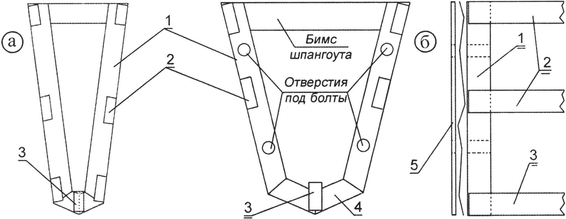
The procedure for manufacturing a “power” frame (Fig. 7) is as follows:
- Cut out a flat part of the frame from a sheet (AMG2n 2.0x1200x2500 mm), mark and drill recesses (only recesses, not entire holes!) for flush installation of blind rivets.
- Cut out reinforcement elements from the box (AD31 alloy 40x20x2 mm) and mark holes for connecting the float elements.
- Prepare hole reinforcement elements from scrap sheets 1 mm thick.
Install (according to the markings) the reinforcement elements in the sections of the box, fill both sides with silicone sealant (layer thickness 4-6 mm), fill the free space with foam from a balloon.
Lubricate the bottom surface of the amplifier with silicone sealant and let it dry for several minutes.
Place a reinforcement on the flat frame element and secure it (for example, with a hand vice).
Drill one hole (preferably from the edge) for a “blind rivet” and connect the parts with a rivet, then drill a hole on the other edge and fasten the second rivet.
Remove the vice, drill the remaining holes and secure the element completely.
Install the rest of the amplifiers in the same way and the frame is almost ready.
After making another frame for the adjacent element (for example, No. 2 for the bow and No. 2 for the intermediate one), it is necessary to attach the frames to each other with their corresponding sides, fix and drill holes for the bolts with which the elements will be connected.
To facilitate the assembly process, you can attach nuts to one of the “power” frames (for example, on Ш2 of the bow element, on Ш5 of the main element, Ш8 of the stern element) (Fig. 8). This will make it easier to tighten the nuts using only one wrench.
To manufacture the “internal” frame (Fig. 9) it is necessary:
- Cut out a flat part of the frame from a sheet (AMG2n 2.0x1200x2500 mm), mark and drill recesses (only recesses, not entire holes!!!) for flush installation of “blind rivets”.
- Make reinforcement elements from the square.
- Sequentially fasten the angles to the flat element, drill holes and secure the angles with “bucket rivets”. The frame is ready.
Stringers are also made of “boxing” (AD31 alloy, 40x20x2). To attach the frames to the stringers, we prepare 40 mm long pieces from a corner (AD31 alloy 30x30x2 mm) for all elements of the catamaran (approximately 80 pieces). Before fastening, we bend the angles to an angle slightly larger than according to the drawing. At the same time, the stressed state of the connecting elements will ensure the reliability of the structure. It is more convenient to attach the pieces of corners to the frames before assembling the power set.
The slipway is mounted to assemble the bow element.
We install the frames on the slipway and fix them vertically with struts. We install stringers on the overlay and fix them with screws. In this case, we fix the rear ends of the stringers tightly in place, and the nasal ends of the stringers should not be connected. We drill a hole in the stringer and also secure the joint with a rivet. We do the same on the other side. We fix the stringers to frame No. 1 with rivets. We bring the bow ends of the stringers in place and fix them with a strip of metal and rivets. Consistently, starting from frame No. 2, we fix the middle stringers, and also connect the bow ends. We attach the keel to the frames. We connect the stringers and the keel with the amplifier with rivets (AMG alloy strip 1.0x100x500 mm).
The most difficult is the marking of the skin (sheets measuring 1.0x1200x3000 mm or 1.0x1500x3000 mm from AMG2, AMGZ or AMG5 alloys). If you make a model, then after assembling the power set you need to wrap it in a sheet of whatman paper and mark the boundaries of the cut. If you place the sheet on the table, you will see that the border is a polygon. You can do the same with the original. We glue four sheets of whatman paper with tape. We fix the edge of the gluing to the slipway overlay with tape or buttons. We bend the sheets around the elements of the power set as tightly as possible. We draw the lines of contact between the “sheathing” and the strength set. We get a drawing that we transfer to a sheet of metal. It should be borne in mind that it is very difficult to bend metal like whatman paper at home. Therefore, we apply the fold lines on the inner surface of the skin, and at the edges you can leave a margin of a few mm. We cut out a blank for sheathing from the sheet and bend it along the lines. We fix the workpiece to one of the upper stringers with 3-4 rivets. We temporarily attach several corners to the opposite edge of the sheathing so that their lower plane is 5 – 7 mm above the edge of the sheathing. Raise the opposite stringer 10 – 15 mm above the overlay. Attach the skin to the slipway lining with screws using corners. We fix the skin to the upper stringers with rivets after 30 -35 mm, and to the middle stringers after 100 – 120 mm. We fix the skin to the vertical elements of the reinforcement of frame No. 2 after 30 – 35 mm, and to the lower elements after 50 – 55 mm. The most difficult part seems to be fixing the bow part of the skin. Several options are possible. You can make an external sheathing reinforcement from a 1 mm thick stainless steel strip and secure it with 4-5 bolts and nuts. Both bolt heads and nuts must have a spherical surface. However, aluminum and steel will form a galvanic couple – and the casing will fail over time. You can make an external reinforcement from a 500x100x1 mm strip of AMG alloy and fix it with rivets. Excess sheathing at the edges is removed with a grinder or file.
The bow element is almost ready, all that remains is to seal the joints, make the deck and fill the compartment with foam plastic.
I used various compounds to seal the joints. During the first assembly, the silicone sealant was dissolved with a nitro solvent (acetone, solvent 646), and the resulting mixture was used to treat all the joints of individual parts, each “blind rivet,” and each bolted joint. The operation to treat possible places of external water leakage was repeated up to 4 times. This allowed us to forget about leaks for 2 seasons. However, in the third year, it was decided to repeat the sealing. A bitumen sealant was used, which was diluted with Galosha gasoline (B-70), and the resulting composition also treated all problem areas. To completely eliminate leaks, individual places (for example, joints of “power” frames) were covered with non-woven material, which was applied to surfaces covered with sealant and sealant was applied on top again.
Each compartment of the float was filled with polystyrene foam (you can use any soft sheet foam with a thickness of 50 – 100 mm). It is not advisable to leave the cargo storage compartments empty – there is enough space for it on the front awning. During a trip to the Gorky Reservoir in 2009, water got into the remaining cavities, the floats were completely submerged in the water, but did not sink, foam plastic helped. It must be remembered that nitro solvents corrode foam.
The production of other elements of the float is carried out similarly to the bow one; the difference in the size of the parts is not of fundamental importance.
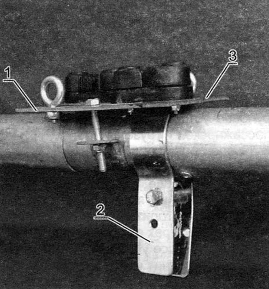
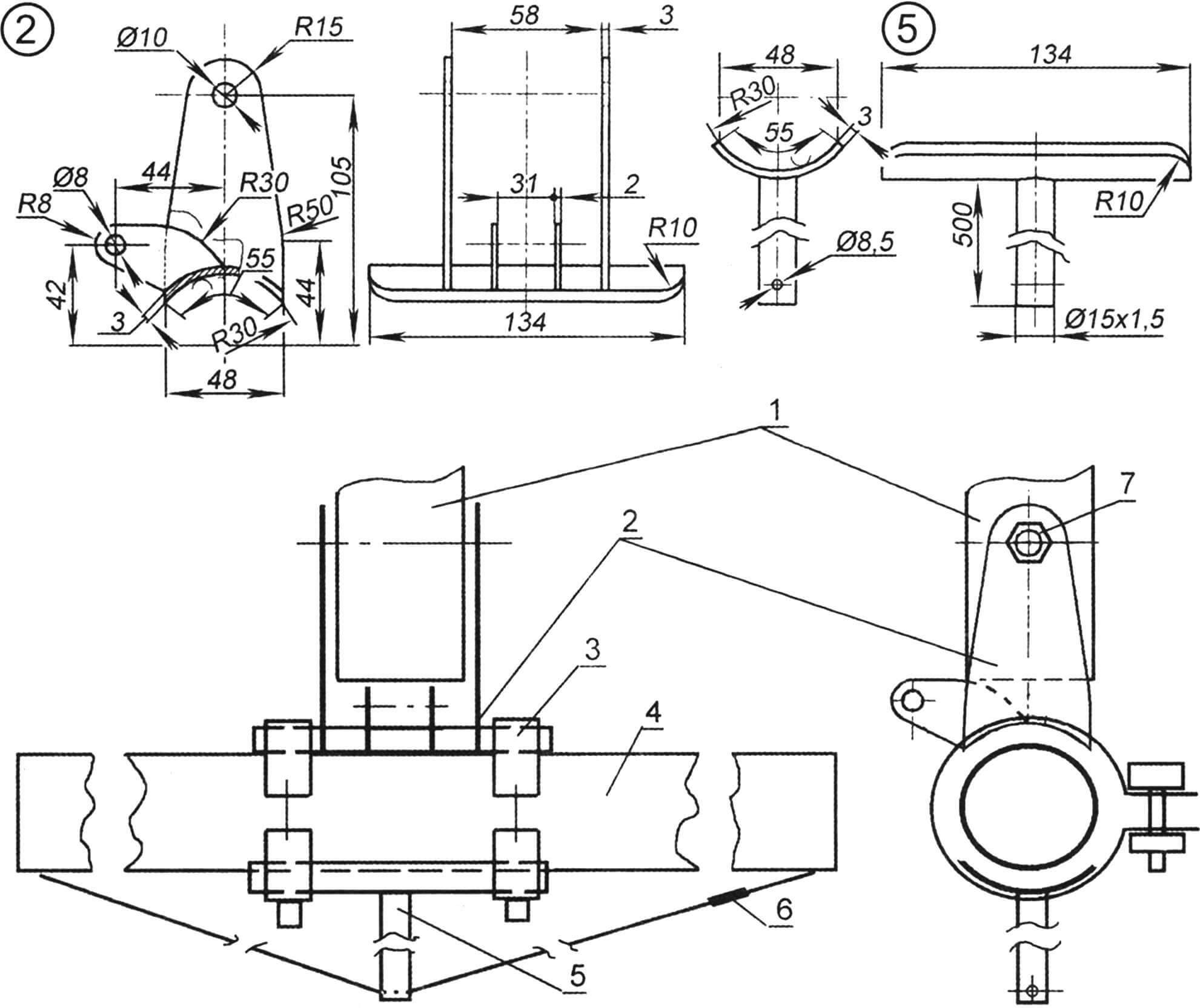
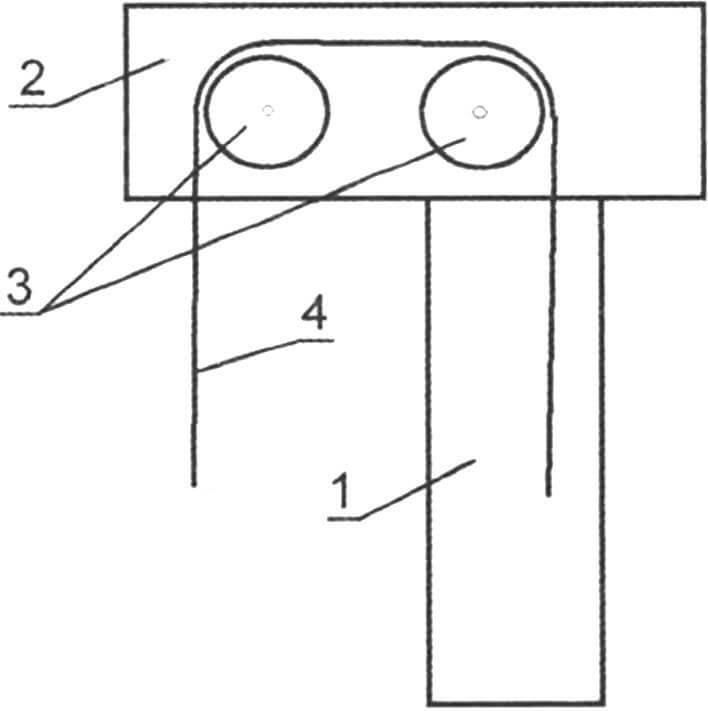
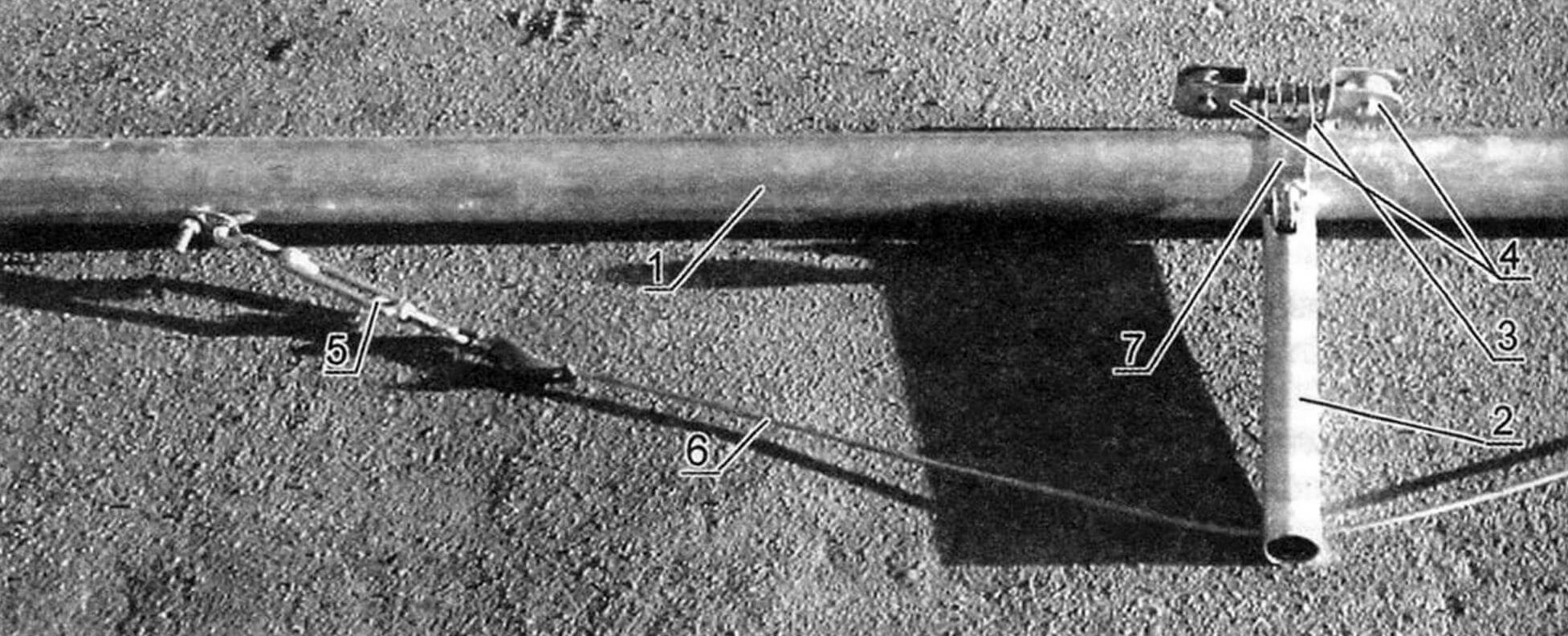
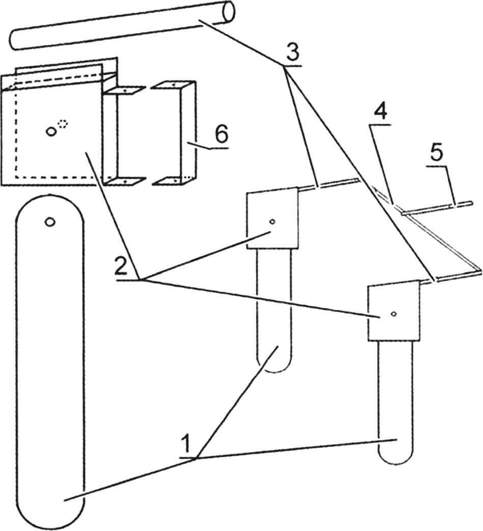
To fasten the beams that combine the floats into a single structure, clamps made of stainless steel strips 1.5 – 2 mm thick and 25 – 30 mm wide are used. The clamps are attached to the stringers with bolts and nuts. It is advisable to strengthen the attachment point of the clamp with a stainless steel plate. This will distribute the load over a larger surface. To fix the beam in the clamp, use an M8 bolt with a self-locking nut.
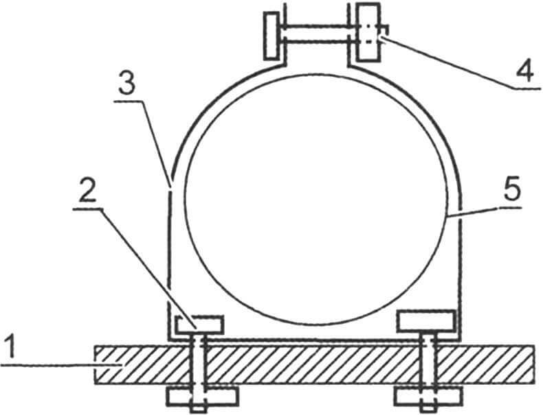
1 — float deck; 2 — clamp fastening bolt; 3 – clamp; 4 – coupling bolt; 5 – beams
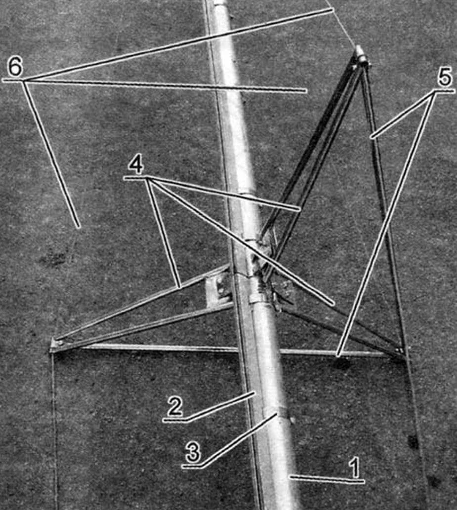
The bow and stern beams are made of pipe (AD31 alloy) with a diameter of 60×2 mm. To fasten the mast to the sub-mast beam, a steel steppe is made. To neutralize the load on the beam, a sub-mast unit is used, which, using a cable 8 mm thick (at least) and a lanyard, creates a force opposite to the pressure of the mast. The step and submast assembly are fixed to the beam with two clamps. A block is installed on the under-mast beam, through which a rope passes to control the centerboard.
The centerboard, the fastenings of the cables for its transverse fixation, and the stopper of the ropes that control the position of the centerboard are installed on the centerboard beam.
1 – mast; 2 – steps; 3 – clamp; 4 — submast beam; 5 — submast unit; 6 — cable with lanyard; 7 – M10 bolt
In the original version, a 40×1.5 mm pipe made of AD31 alloy was used to make the mast. However, the strength of the structure turned out to be insufficient. Subsequently, a 50×2.5 mm pipe was used to make the mast. The mast consists of three sections. The lower and middle ones are 3 m long, the upper one is 1.5 m long.
1 – mast; 2 – bracket; 3 – block; 4 — mainsail halyard; 5 – lypase; 6 — bracket for fastening the lip seal to the mast
The face-groove is made of “boxing” 15x15x1.5 (AD1 alloy). One of its walls was bent inward with a hammer so that the face groove would fit well to the mast. On the opposite side, a cut was made with a width of 2.5 – 4 mm. I carefully sanded the edges of the cut so as not to subsequently damage the luff of the mainsail. The face-groove was secured to the mast with clamps with a threaded tightening. The distance between the clamps is from 200 mm at the bottom to 400 mm at the top of the mast. The top of the mast was equipped with blocks for wiring halyards. The mainsail halyard is passed inside the mast. After setting the mainsail, the lower end of its halyard is laid on the cleat at the bottom of the mast.
1 — submast beam; 2 — emphasis; 3 — steps (place of fastening of the lower part of the mast); 4 — blocks of running rigging; 5 – lanyard; 6 – cable; 7 — clamp-bracket
The stay is fixed at 3/4 of the mast height. A spinnaker or gennaker block can be attached above the top stay attachment point.
The spreader is made of pipes with a diameter of 12×1 mm, the material is stainless steel. The spreader is installed at the junction of the lower and middle bend of the mast. Fixed on the mast with a clamp.
1 – mast; 2 – lypase; 3 — fastening of lykpaz; 4 — spreader stands; 5 — spreader spacers; 6 — rhombovates
The greatest difficulty, in my opinion, is making the sails. I sewed them myself, measuring seven times and only then cutting and sewing each piece into place. It is quite difficult to describe this process briefly and clearly. It is better to study the details in specialized literature. In addition, there are computer programs for calculating sails. For those who have the opportunity, it is better to order the manufacture of sails in special workshops.
The shrouds and diamond shrouds are made of stainless steel cable 5 mm thick. Due to the fact that the mast is made of a 50×2.5 mm pipe, three pairs of cables are installed on the catamaran. The upper ones are attached at the junction of the upper and middle elbow of the mast (approximately 4/5 from the step). The other two pairs reinforce the middle (above the spreader) and lower (below the spreader) parts of the mast. Front shrouds appeared on the modernized design. Their purpose is to reduce such vibrations of the floats, when the nose of one float rises and the nose of the other goes down.
The ends of the rigging cables are fixed with clamps made of 8×1 mm copper pipe. To protect the cable strands from chafing, it is advisable to make thimbles. For final adjustment of the length of the cables, turnbuckles with M8 threads are used.
The cable stays are made from stainless steel strips 1.5 – 2 mm thick and 20 – 25 mm wide. It is advisable to attach the shrouds to the upper longitudinal stringers in the area of the centerboard beam. To prevent the lanyard hook from falling out of the cable stay hole, after tensioning the cables, it is necessary to wrap the hook with tape, electrical tape or adhesive tape.
1 – centerboard; 2 — centerboard lifting rope; 3 — submast beam; 4 – clamp; 5 — stoppers; 6 – blocks; 7 — rope for installing the centerboard in the working position; 8 — cables that prevent lateral movement
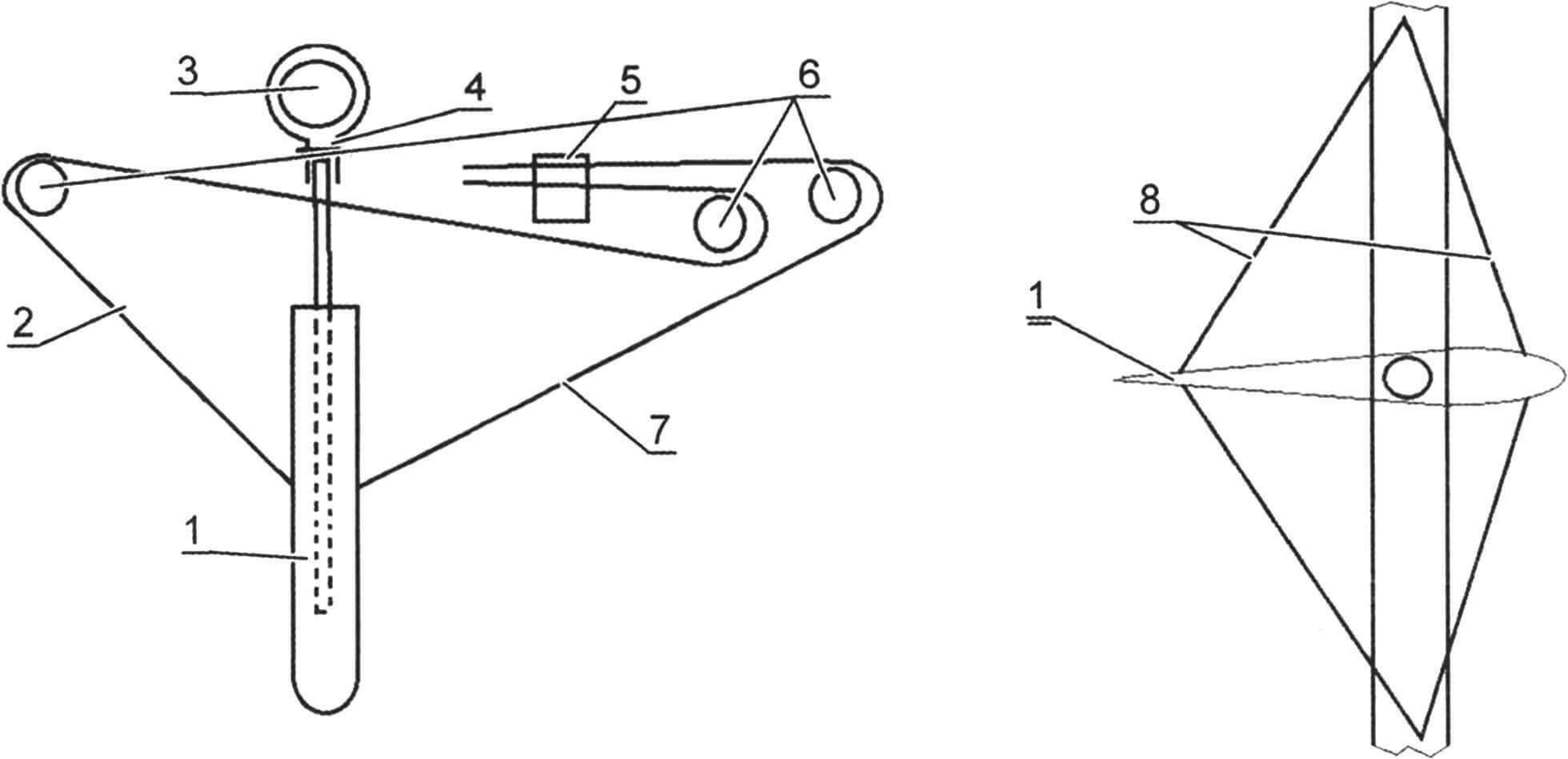
The centerboard is profiled, made of 1 mm thick sheet (AMG alloy). Its power element is a stainless steel pipe with a diameter of 15 mm. The rear section is riveted with “blind rivets” measuring 3.2×8 mm, from which the core is removed. The pipe is pre-installed in the middle part of the centerboard and, after connecting the rear section, it is fixed to the skin with “blind rivets”. A hole is drilled in the upper part of the pipe to install the centerboard in a rotating bracket attached to the beam. Ropes are tied to the middle of the front and rear edges of the centerboard, with the help of which it is installed in the working position or removed from the water to the stern. To fix the centerboard in the center plane of the catamaran, cables are used, the length of which is adjusted by turnbuckles. A good centerboard can be made from wood, or even better, molded from fiberglass with epoxy resin. But this is more difficult than making it, like the rudder feathers, from sheet metal.
The steering device is paired and consists of banners (steering boxes) with a rudder blade, tillers, a connecting rod and a handle. The steering boxes are made from sheet metal (you can use scraps from deck blanks) and 30x30x2 corner pieces. The elements are connected with bolts and nuts or rivets. The rudder blade is made similarly to the centerboard, the tube is made of aluminum alloy, the internal cavity can be filled with foam plastic. At the top of the rudder blade there is a hole for attaching the rudder blade to the steering box. To fix the rudder blade in the working and raised position, the sorlin is fixed with cam stoppers attached to the tiller. The tubular tiller is bolted to the steering box. The connecting rod (pipe, alloy AD31 30×2.5) is attached to the tillers with bolts and nuts. The tiller extension is attached to the middle part of the connecting rod with a special bracket. For ease of use, the end of the extension cord is wrapped with a fabric roll of adhesive tape (in no case with plastic tape). You can make a handle at the end of the extension. It is advisable to make the extension (or handle) rotating around its axis.
1 — rudder blade; 2 — stock (steering box); 3 — tiller; 4 — connecting rod; 5 — tiller extension; 6 — bracket on frame No. 9
To fix the steering boxes on the aft frame (W9), a bracket made of a stainless steel strip 2 mm thick and 20 mm wide is attached. The boxes are secured with a long pin.
The stern beam is equipped with a wiring system and boom sheet stoppers. The staysail sheet stoppers and other elements of the running rigging are located in the centerboard beam area.
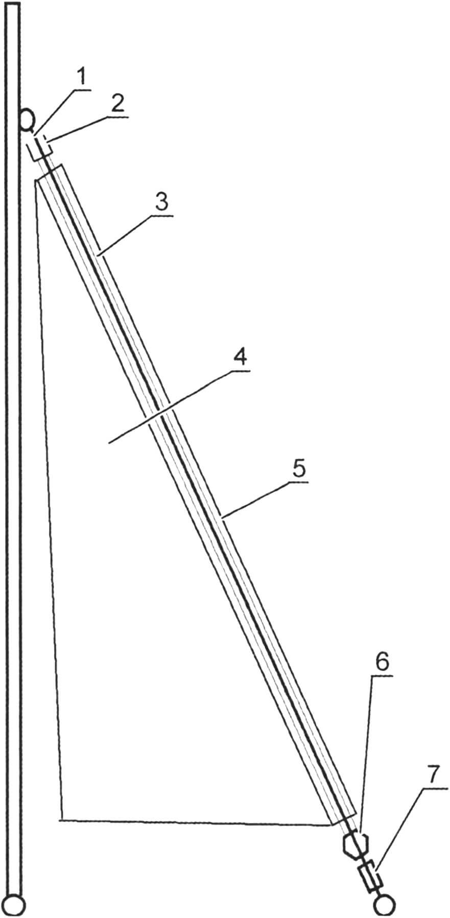
1 – forestay; 2 – upper bearing; 3 — fairing; 4 — staysail; 5 — jib pocket; 6 — spin coil; 7 – lanyard
To make a furling jib, we put an upper bearing and a fairing pipe on a forestay blank with an equipped top light. There is a pocket on the luff of the jib; we put the jib on the fairing. Then we put on the lower coil-twist. In this case, it is advisable to equip the pocket with 1-2 gaps in those places where there are loose joints in the fairing elements. For subsequent fixation of the fairing joints, it is necessary to provide sections of pipe of smaller diameter, placed on the forestay cable. Then we will equip the lower fire. Instead of tubular compression, you can secure the cable with several screw stoppers. Before installing the jib, all elements of the fairing are fixed, the fairing is attached to the upper bearing and the furling spool. After this, you can attach the upper part of the forestay to the mast. We trim the jib pocket by hand so that the sail sits tightly on the fairing.
Of course, mistakes happened during the construction of the catamaran, and it was sometimes difficult to correct them, but nevertheless the vessel was built and has been successfully operated for many years.
ASSEMBLY AND TESTING
And now the moment has come when all the components of the vessel are ready. But don’t rush to the water. I recommend carrying out the first assembly on land, in a place where there is access to electricity: some hole doesn’t fit, you need to cut off the excess metal, or you never know what needs to be corrected. And when there is an electric drill, a jigsaw, an electric saw nearby, it is easier to eliminate defects.
Assembling a catamaran begins with connecting the float elements. It is advisable to loosen the fasteners in the compartment connections, apply sealant to the bolts, let them dry for 15-20 minutes and tighten the bolts again. If no leaks are found during testing, you can leave this assembly until the end of the season.
On the sub-mast beam we install and fasten the steps, the sub-mast assembly, and on the centerboard – centerboard rope stoppers and a centerboard bracket. These beams can remain in this “equipped” state permanently.
1 – stern beam; 2 — shoulder strap; 3 — shoulder strap block; 4 — sheet boom stopper; 5 — gigashkot blocks; 6 — gikashkot; 7 – boom; 8 – stopper; 9 — rope shoulder strap of the boom coat
Be sure to raise the sails, check whether the mainsail moves freely along the groove and whether the blocks and stoppers work well. We check the operation of the mainsheet strap and the main sheet stoppers. We unfold and furl the jib several times. We check the correct installation of the sheets and the operation of the stoppers. We check the position of the mast: deviation from the vertical in the transverse plane is not allowed. The tilt of the mast back can be no more than 6°. We tighten the guy lines of the mast. Shaking the mast forcefully, we check whether the stoppers and tubular clamps of the shrouds and forestay are holding well. We install the centreboard, check the fit of the cables and the wiring of the ropes. We assemble the steering device. We stretch the awnings of the passenger and cargo decks.
1 – feather; 2 — steering box; 3 – fastening device; 4 — tiller; 5 — weed stopper
After checking and adjusting all the elements, we disassemble the catamaran for transportation to the water.
The preparation of the catamaran for the trip is carried out on a horizontal area a few meters from the water. It is advisable that three people participate in the process, this will make assembly easier and faster.
My trailer allows me to transport the bow compartment assembled with the intermediate one, and the stern compartment with the main one. So first we completely assemble the floats, not forgetting about sealing the joints. Then we attach bow and stern beams to one of the floats (for example, the left one). We place the right float under the right ends of the beams, align and tighten the bolts. We install centerboard and submast beams. We assemble a mast from sections and tighten the diamond shanks. We bring the lower end of the mast (spurs) from the bow, install it in the steps and fix it with a pin or bolt and nut. We straighten the shrouds along the sides and attach the stay to the mast. To raise the mast, it is advisable to use a winch, such as the one found on boat trailers. In addition, it is necessary to tension the middle pair of cables on the sub-mast beam. This will prevent the mast from falling sideways. The use of a winch and measures to prevent it from collapsing make it possible to install the mast even alone. It is necessary to exclude the presence of strangers in the mast lifting area. After installing the mast, we fix the stays and stays vertically to prevent the mast from falling. We check and adjust the position of the mast.
1 – mast; 2 — rhombovant lanyard; 3 — boom guy block; 4 – grotafal
We install the centerboard and steering gear. We attach awnings to the bow and stern beams and tighten them with ropes. We lower the catamaran into the water and let it stand at a depth of no more than 1 m for 15-20 minutes, checking the tightness of the float stops through the open decks. If there are no leaks, we seal the decks. We turn the centerboard and steering devices.
We set sails near the water’s edge: mainsail, staysail.
ATTENTION! When on the water you must ONLY wear a life jacket. Special gloves must be worn on your hands. Check if you forgot your oar; let it lie on the bow cover, secured with a rubber band.
I am not an ascetic, but I will speak categorically: water and alcohol are not compatible. When my friends and I assembled the first catamaran in 1990, a tradition was born that is observed at the beginning of each season.
The hull of the catamaran (and nothing else) is sprinkled with cognac.
Choose a time for your first exit when there are no boats or people on the water, the wind is weak, and there are no waves. May there be a boat next to you with friends ready to help… and may you not need help! Be patient. There will also be wind and waves, whistling gear and splashes in the face…
V. TEREKHOV
Recommend to read
 THE PATCH OF THE TIRES…
I read in the journal "modelist-Konstruktor" No. 6, 1993 article "Vitamins grow on the balcony." From her I learned about the use of pyramids of old tires as a vertical garden. Intrigued...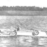 VENUE, COMES ASHORE
Amphibious vehicle design N. M. Purtova. Doesn't that sound nice, getting up early in the morning, roll the boat out of the garage, lay a tackle, get in, press the starter and... to take...
