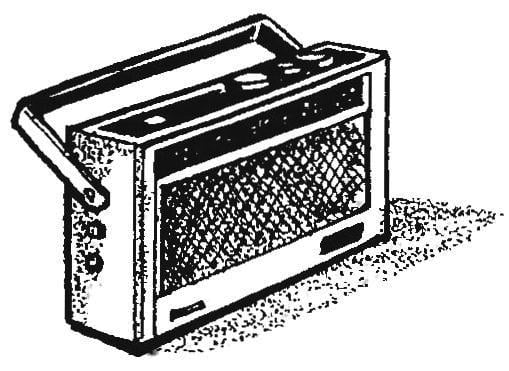
 People sometimes just have no time to twist knobs of the receiver to switch from one frequency to another. Here comes the advance settings of some of the most popular stations, pressed a button and listen to the desired program. In this mode you will be able to work any long-wave radio with a homemade console, designed for several fixed frequencies in the range of SV.
Console tronsmart s95 is a Converter that converts the signals from medium wave radio stations into signals of intermediate frequency. This drive corresponds to long-wave station, which in this area is clean none of the broadcast.
VТ transistor 1 operates in Converter with combined local oscillator. Input circuit form a coil 61 of the magnetic antenna and the group of capacitors C1—C6, serially connected first sections of the respective buttons. So, SB1.1 is active L1С1С2 configured, for example, the radio station “Mayak”. By pressing the SB2 (the other buttons, of course, you are automatically issued) its first section SB2.1 includes, respectively, L1С3С4 tuned to a different broadcast. The third program will be bugged by clicking on SB3 when the input circuit (thanks to the accurate work SB3.1) is created by coil L1 in a pair of capacitors C5 and C6.
Simultaneously with the input switches heterodyne circuits. They are formed by parallel connection to the coil L3 corresponding pair of capacitors (C7— C8, C9—C10 or C11—C12). The switching element is a second contact selected buttons (SB1.2, SB2.2 or SB3.2).
In any case, the fixed settings of the heterodyne circuit at 380 kHz higher than the same parameters of the input circuit. Differencing the frequency is highlighted on the collector load of the transistor VT1, which is a broadband filter. The signal from this filter is removed and through a capacitor C19 is transmitted to the input socket of the external receiver antenna. The future is no different from taking the long-wave broadcast stations.
Now for the details of the Converter. Coils L1 and 62 are wound on frames of heavy paper put on the web 115x20x3 mm ferrite 600НН. Contour coil has 70 turns of wire PALSO with a diameter of 0.12—0.15 mm, its winding — tight single layer. The connection coil contains seven turns of the same wire.
Coils 63 and 64 of Commerce and manufacture. In particular, it is suitable heterodyne from the old transistor radios of the type “Falcon-403”. Also ready is recommended to use an RF filter is designed to work in tandem with the capacitor 1000-1500 pF (for example, “Selga-404”). Perfectly acceptable and a homemade counterparts named coils.
Resistors — MLT, MT of any power (to 0.5 W); permanent capacitor — KS, KLS, KD, KT, adjusted — CPC-M, CPC-1; switches — series П2К (both single and combined three-button, radio button selected position).
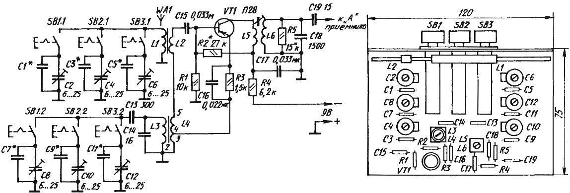
Electrical schematic and installation of radioperedachi Converter into three programs that run in the range of SV
Mounting consoles can run both print and mounting method.
As a power source for the Converter easier to use a stand alone battery. Suitable options of consoles from a powerful radio or network adapter.
The establishment of the Converter begins with the inspection of a collector current of the transistor, which should be in the range of 0.5—0.7 mA.
If necessary it is adjusted with the selection of the value of the resistor R2.
Search for radio stations held subsidiary of KPE — a two compartment unit variable capacitor (e.g., CPV-2, the illustrations are conventionally not shown). In the instructions attached to it a table or graph is based on changes in the capacitance of the rotation angle of the movable plate. This and guidance, connecting KPE temporarily instead of a group of capacitors in the input and heterodyne circuits.
Connecting the output of the console with a socket receiver ANTENNA, tune to one of the radio stations operating on the low end of the range of SV, where the capacity of the “dvuhsektsionnogo” should be about 300 pF. The moving coil L1 along the rod antenna to achieve maximum loudness. The angle of rotation of the rotor of the variable capacitor assess the capacity for both sections. Subtracting from it half the capacity of “podstroechnye” (15 pF), get the value of the capacitor with constant capacitance connected to receive the station parallel to the trimmer. The calculated value is rounded up to the nearest standard values and install one such capacitor in the input and heterodyne circuit. After that, regular “trimmers” achieve the greatest sound volume.
On the high end of the range is set with the connection sections of the variable capacitor adjusted in parallel to the capacitors. If the signal is weak desired station, the sound volume increase with rotation of the rotor rigged capacitor input circuit. Then we achieve maximum volume adjustment circuit of the drive it “postroeniem”. The self-excitation of the instrument, if it appears, remove the selection of the proper value of the resistor R5.
And another tip. In the process of debugging the Converter, you cannot change the setting for the base receiver. And henceforth it was easier to restore, on the scale make a special label.
Yu PROKOPTSOV
Recommend to read
 THE EJECTOR CHIMNEY
What good is forge from the point of view of the Stoker? Of course, the "blower" to burn any fuel to the ground. But if someone dares to apply Gornova blast in his home oven, the...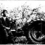 MY SOROKOVINY
Not naraduyus its homemade and truly versatile tractor with 40 HP, although the time and effort it took a lot. And most of these costs took the Assembly design, and procurement...
