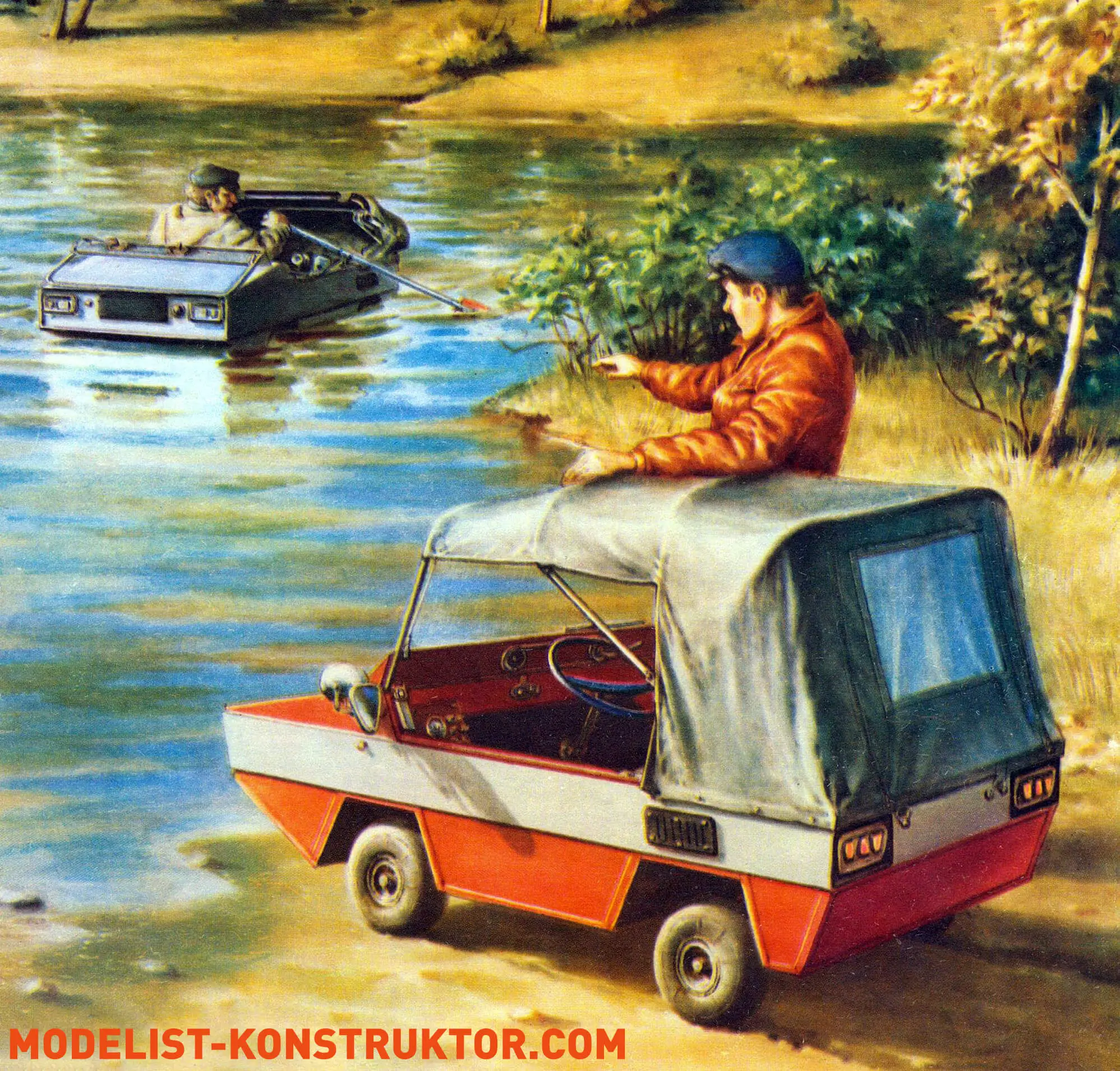
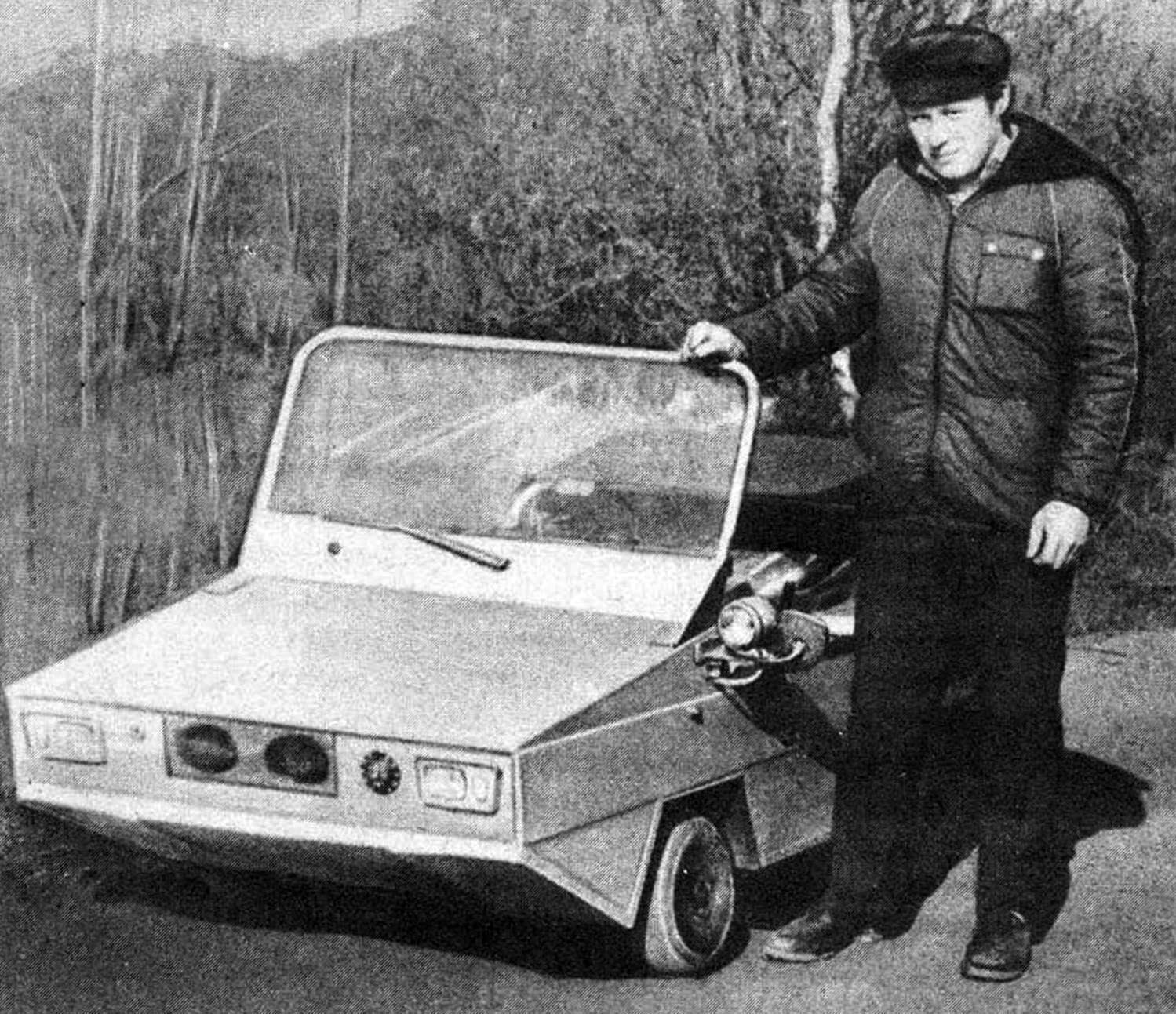
A FLOATING CAR with a moped engine was built by A. Natarov from Yaroslavl. I would like to introduce MK readers to the amphibious vehicle I assembled. I designed it to solve a number of problems and contradictions that arise in practice during design. There were quite a few, but it makes sense to highlight the main ones.
1. Is it possible to build a car with a 50 cm3-class engine? What speed and payload would it have?
It turned out—yes! With a curb weight of 80 kg, it easily carries an adult at 30–35 km/h (on asphalt), provided the car has compliant wheel suspension. A rigid-suspension version is much harder to control—the vehicle hops and ignores the steering, which shows up already above 20 km/h. At slightly-beyond-bicycle speed (16…18 km/h) it easily carries two adults and climbs any highway grade. With a solo driver it drives onto a ramp with a 15° incline from a standstill.
2. Is it worth tuning the engine?
It turned out to be pointless. When forcing the engine, the power gain comes from higher rpm. Torque does not increase. The engine curve becomes steeply falling. All of this hampers launching from rest and demands a multi-speed gearbox. Interestingly, the SH-51 and D-6 engines behaved identically with the same gearbox despite different power ratings.
3. What are the minimum dimensions for a single-seat amphibian, and what speed is possible?
I assembled my machine in an ordinary apartment on the tenth floor. Its dimensions were limited by the freight elevator and the crate that served as the garage—2000×2000×700 mm. The side height is 300 mm; this lets the amphibian stay afloat with two adults, immersing a little above half the side. With only the driver the draft is just 120 mm. On the water it is very stable—you can cast a spinning rod, sit on the hood, side, or stern without risk of capsizing. The low-mounted engine and running gear acted as ballast. I think the minimum feasible dimensions for a single-seat version can be reduced to 2000×800×400 mm.
With these dimensions, fixed “landing gear,” and “box” hull lines, hydrodynamics limits water speed to about 3 km/h. I confirmed this by getting 1 km/h with a stationary waterjet (poor efficiency of the transmission and pump); speed on oars and with a Sputnik outboard (2.5 km/h) was the same. So I abandoned both the waterjet and outboard in favor of oars. Later I fitted aluminum-channel paddle cleats to the wheels and reached… 0.5 km/h. Steering via lean worked fine for spinning, which suited me.
A warning for anyone building an amphibian: if the vehicle is not designed to plane, its water speed depends solely on hull dimensions—the longer and narrower the hull, the faster; the wider and shorter, the slower. Economical power required for water travel is typically 1/3…1/5 of what is needed on land. The conclusion is simple: build an amphibian using traditional automotive principles, seal the hull, and provide a water drive. These vehicles are mainly land machines. They spend little time in the water and cover short distances. They are needed mostly by anglers and occasionally tourists. If you want a fast amphibian on both water and land, build a boat and put it on wheels—there is no other way.
4. What about off-road ability and fuel consumption?
Fuel consumption doubled (vs. a moped) to 4 L/100 km due to reduced speed and higher mass. Most garage builds based on motorcycle engines are not paragons of efficiency and gulp up to 10 L per 100 km! And since an overloaded engine loses power after 15,000 km, the dream of commuting daily in such a machine is a clear utopia. City transport is faster and cheaper.
As for mobility, the amphibian is almost like a moped. The latter, however, handles sand much better. Small-diameter “balloon” airplane tires with a round tread are a poor drive: they cut ruts in soft soil, slip, and the machine ends up belly-sitting. Even paddle cleats did not help. Overall, the cross-country capability of DIY amphibians should match that of conventional cars; a layout with a single rear driving axle and ground clearance equal to wheel radius works fine. Even army amphibious trucks cannot always climb a bank without a winch.
5. What additional equipment does an amphibian need?
My modest experience showed that bilge equipment comes first. Without it the machine quickly becomes a sort of submarine. Water can enter through loose seams, seals, other joints, in the rain, during a clumsy launch, or when meeting a hefty wave. Make sure water inside drains to a point dictated by trim and list, without being trapped by bulkheads. Then it’s easier to remove. A scoop or pail is simplest, but a manual or electric pump—or an ejector if you use a waterjet—can be provided.
Second comes a winch of any type. I realized this after the first “sail,” pulling the vehicle out of a pond. Even at only 80 kg mass it was hard work. The simplest (but least convenient) is a wheel winch. Next in simplicity and availability is a manual hoist—you can pull the car out of anywhere with it. The hardest to make is a transmission-driven winch, yet in my case it was actually the easiest. To test it I hooked an anchor onto a gate beam, checked that it held, engaged the clutch—and seconds later found myself in the air with the machine. Thanks to the winch the amphibian can climb the most inaccessible bank. Even a 2 m sheer drop without a foreshore or shallows is no obstacle.
Next, equally important, is ensuring unsinkability or simplifying salvage after swamping. All amphibious cars, even military ones, sink when flooded. You simply can’t fit flotation blocks inside—their volume would fill the hull. The only option is to equip driver and passenger with life jackets so they can leave quickly, and provide buoys: as they surface, they pull up lines you can use to recover the “victim.”
It is also useful to integrate a rubbing strake into the bodywork to protect it from damage, dents, and scratches while mooring alongside other craft. For the same reason plan the placement of headlights, sidelights, and rear markers, since docks and gangways can knock out a headlamp or rip off marker lights when the boat is moored in choppy water.
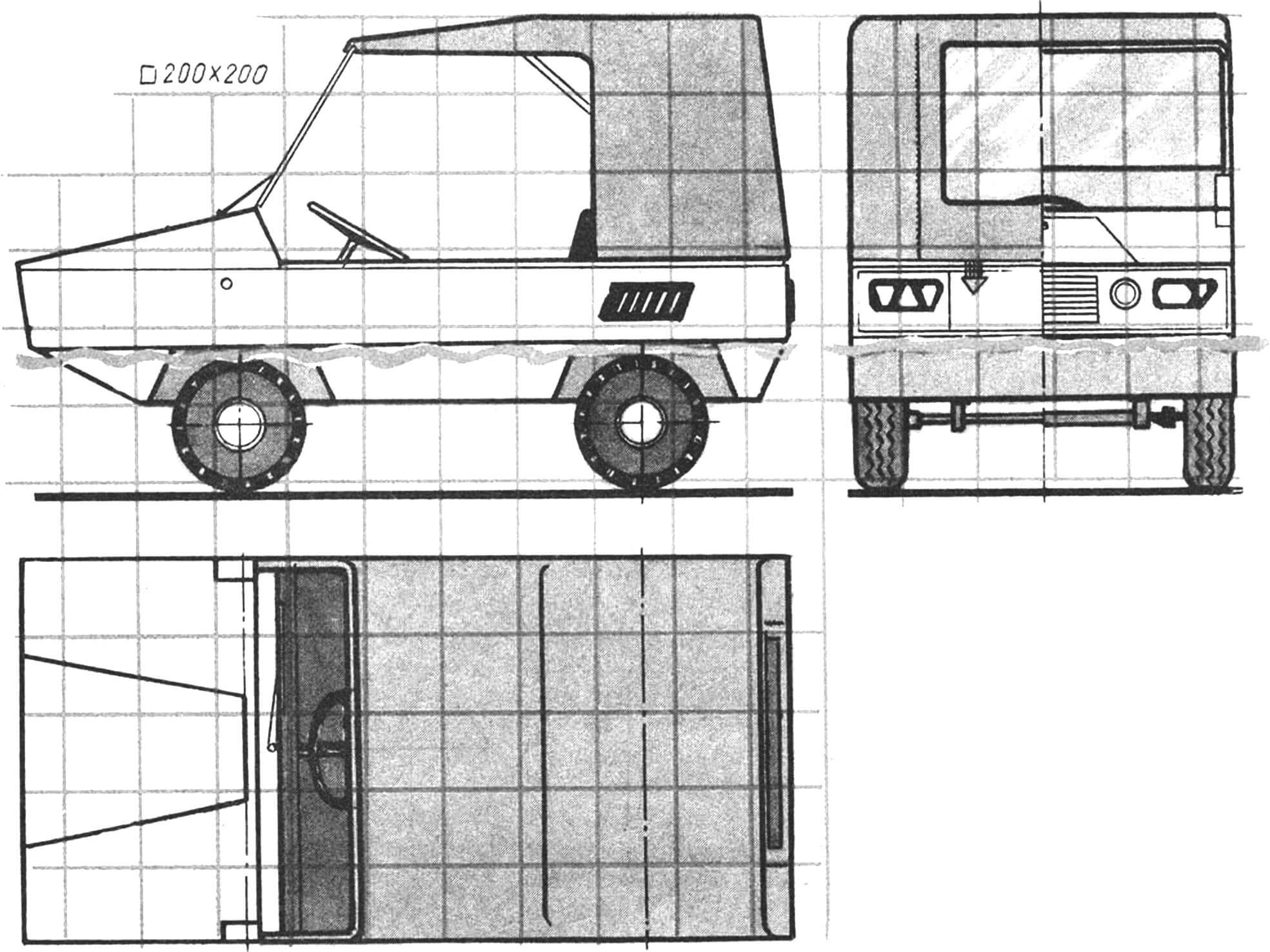
My amphibian was built as a sort of model—or rather, a rolling laboratory—so it features many simplifications. I did not expect high speed, so I rejected suspension on both axles. The body is load-bearing and assembled using “boat” technology. The only difference is two keel beams and oblique frames, which made wheel-well mounting easier. Frames No. 1 and No. 2 converge into a triangle and share a single beam serving as the dashboard. Frames No. 0 and No. 5 are closed off; they act as transoms. The aft transom is reinforced and carries a pad for an outboard motor. The body is skinned with hardboard, and the wheel wells are made of roofing steel. Assembly was jigless; all parts were fastened with nails and nitro putty used as glue. The finished body was filled and painted with oil paint.
The front and rear axles are essentially sports-kart units but lack brakes. Brake shoes swell in water and wear quickly. Both axles bolt externally to the keel beams. Steering is also kart-style; the linkage sits outside the hull and has two tie rods connected to the pitman arm on the steering shaft. The steering shaft is sealed like a daggerboard trunk on a sailboat: a tube with a flange and bearing is fixed to the bottom as a “well,” and the shaft rotates inside it. The upper section with the steering wheel is removable so it does not interfere when rowing, and it clamps in place with a quick-release lever from a Kama bicycle.
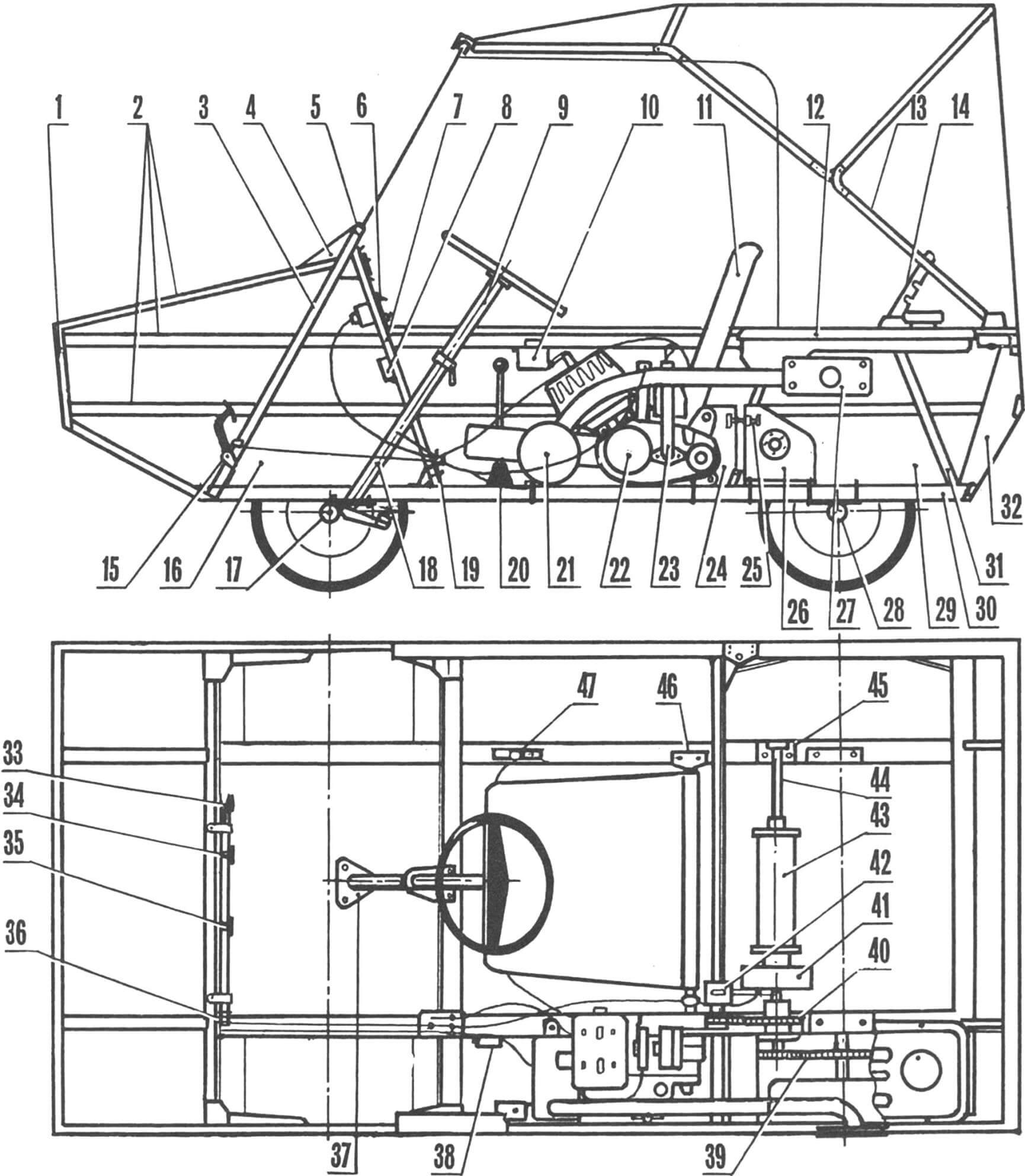
1 — front transom, 2 — longerons, 3 — frame No. 1, 4 — windshield hinge, 5 — windshield frame, 6 — dashboard, 7 — frame No. 2, 8 — turn-signal relay, 9 — removable steering-column section, 10 — ignition coil, 11 — seat, 12 — fuel tank, 13 — folding top frame, 14 — top-frame latch, 15 — pedal assembly, 16 — front wheel well, 17 — front axle, 18 — steering-shaft well, 19 — common pedal-cable tensioner, 20 — gearshift lever, 21 — muffler, 22 — SH-58 engine, 23 — dipstick, 24 — sliding engine mount, 25 — chain-tensioner, 26 — transmission-shaft mount plate, 27 — exhaust-flange, 28 — rear axle, 29 — rear wheel well, 30 — keel beam, 31 — frame No. 4, 32 — rear transom, 33 — accelerator pedal, 34 — brake pedal, 35 — clutch pedal, 36 — control-cable gland, 37 — steering-well flange, 38 — brake-light switch, 39 — drive from transmission shaft to axle, 40 — chain drive from engine to transmission shaft, 41 — brake drum, 42 — brake-shield holder and link, 43 — winch drum, 44 — transmission shaft, 45 — bearing housing, 46 — seat-mounting brackets to keel beam, 47 — gear lever.
The rear axle has no differential; both wheels are driven, which boosts traction and hardly affects handling—the machine pivots almost in place like a kart. Torque reaches the axle via chain; to adjust tension, the axle can slide aft. The axle shaft spins in two bearings whose housings bolt to the keel beams.
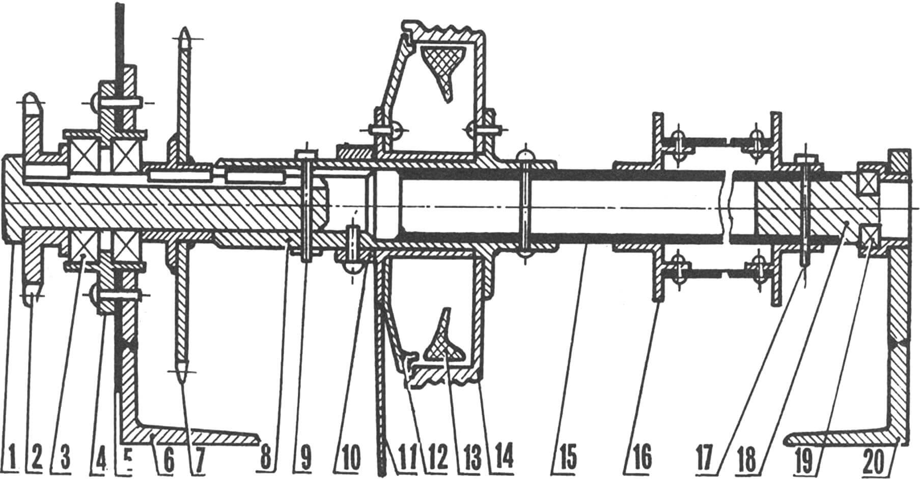
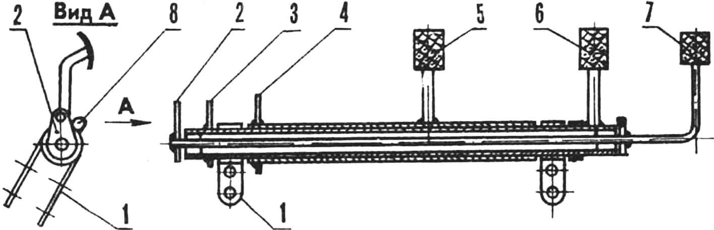
1 — keyed pin, 2 — sprocket (drive from transmission shaft to axle), 3 — double-lip sealed bearings (from the Moskvich-412 water pump), 4 — bearing-housing body, 5 — wheel-well wall, 6 — left transmission-shaft support (bolts to the keel beam), 7 — driven sprocket (drive from engine to transmission shaft), 8 — transmission-shaft housing, 9 — split-pin retainer, 10 — circlip, 11 — brake-shield link, 12 — brake shield, 13 — brake shoes, 14 — brake drum, 15 — transmission-shaft extender, 16 — self-recovery winch drum, 17 — winch-drum retainer pin, 18 — transmission-shaft plug, 19 — support bearing, 20 — right transmission-shaft support (bolts to the keel beam).
The transmission (intermediate) shaft receives torque from the engine via chain drive whose driven sprocket is easily swapped. Tooth count ranges from 13 to 25 depending on load and terrain. The torque then either goes to the winch drum, which spins freely on the intermediate shaft and locks with a removable pin, or passes through a seal and chain to the rear axle. The same shaft carries a brake drum acting on both the axle and the winch.
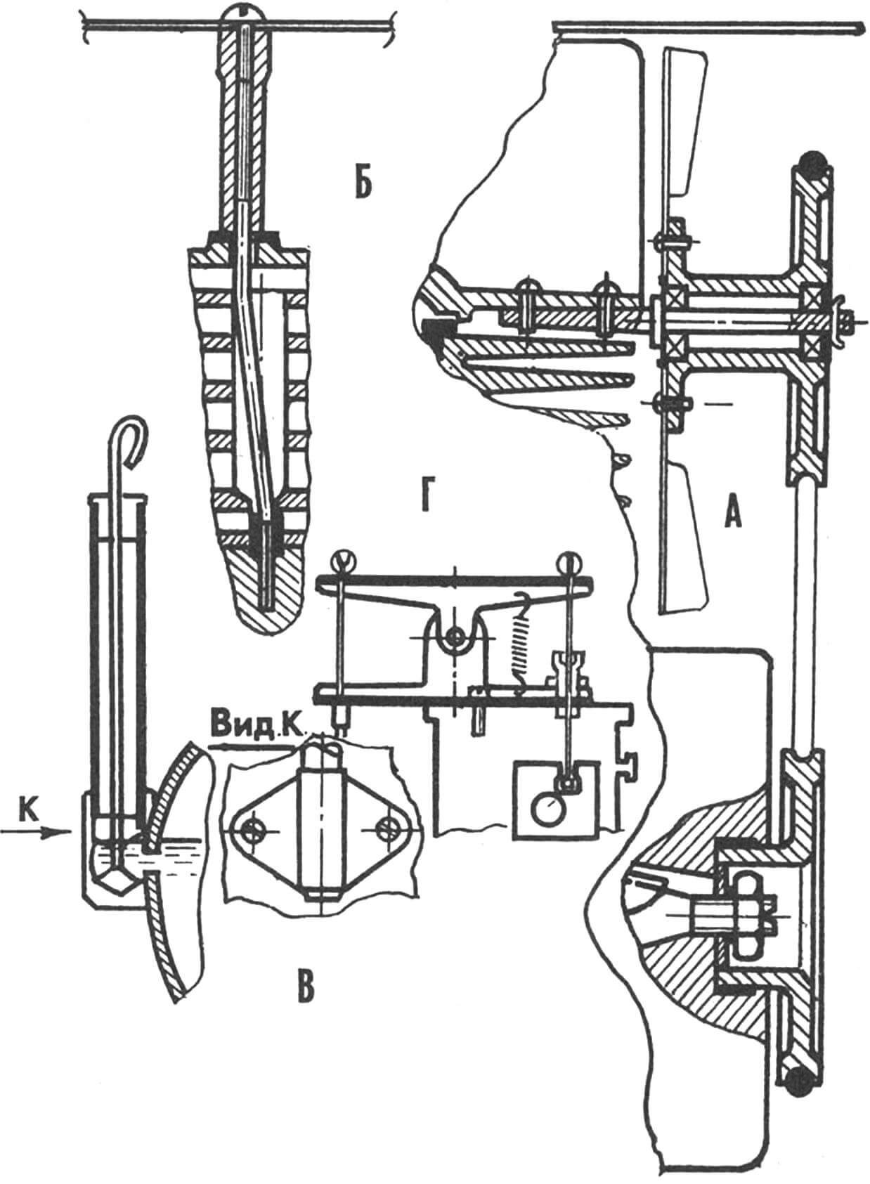
A — forced-cooling installation, B — rotating the cylinder head 90°, C — installing an oil dipstick, D — throttle-return booster.
The engine is mounted on the left keel beam and slides with the muffler and base to tension the chain. In the SH-58 crankcase a pedal shaft from an SH-51 engine replaces the kickstarter shaft. The left crank arm was cut near the wedge, and a tube welded to the right arm; as a result the kickstarter ended up on the right and is easily cranked with the left hand. The engine was converted to forced cooling. The head had to be rotated 90°. Because the studs prevented this, I drilled the holes in the cylinder jacket out to Ø12 mm and bent the studs to align with the head in its new position. The head nuts should be lengthened and deflectors screwed to them. The cooling fan is belt-driven from the crankshaft and spins on an axle mounted between head and cylinder with two screws. The pulley is fastened to the crankshaft with a hollow bolt threaded into the flywheel. The drive pulley is a sealing ring from a YaMZ-236 cylinder liner. Engine controls almost match the Pioneer kart layout.
The seat and top frame are made from folding-bed parts. The top can be rolled up on three sides; its openings close with zippers. The windshield folds onto the hood when needed.
1 — clamp securing the pedal shaft to frame No. 1, 2 — throttle-pedal lever, 3 — brake-pedal lever, 4 — clutch-pedal lever, 5 — clutch pedal, 6 — brake pedal, 7 — throttle pedal, 8 — lever stop (welded to the left clamp).
The vehicle carries front and rear turn signals, brake lights, and marker lamps. All lighting equipment, including dipped headlights and the searchlight, comes from bicycles and mopeds. A horn is also provided.
The amphibian proved reliable and convenient. Over one season it covered about 2,000 km along the roads and rivers of Yaroslavl Oblast. There wasn’t a single breakdown, though the engine was extremely temperamental.
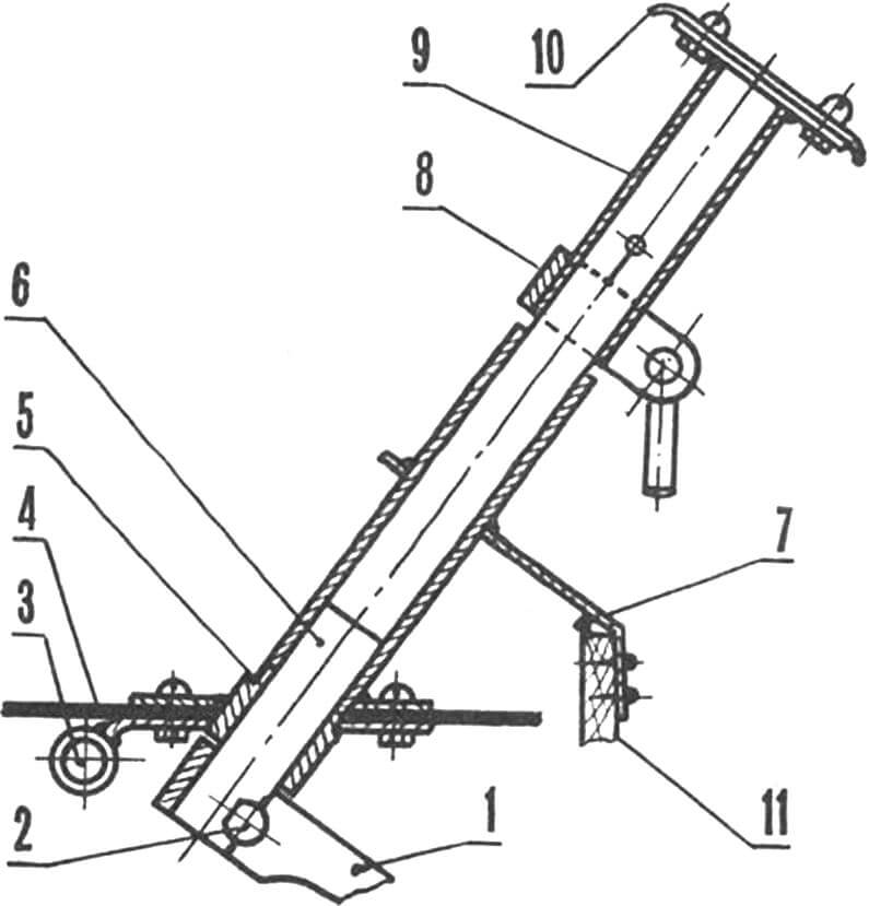
1 — pitman arm, 2 — arm-retaining wedge, 3 — front-axle beam, 4 — bottom, 5 — steering-column well with flange, 6 — pitman shaft, 7 — auxiliary well support, 8 — extension clamp, 9 — removable steering-column extension, 10 — steering-wheel crosspiece, 11 — frame No. 2.
Wherever the vehicle showed up it drew genuine delight, surprise, and—admittedly—envy. There were also “encounters” with traffic police, who often stopped me out of curiosity: according to the rules, a vehicle with an engine under 50 cm3 and speed below 40 km/h is classed as a moped or motorized bicycle, needs no registration, and can be driven without a license.
Unfortunately the amphibian lasted only one season. Built as a test bench, it was nevertheless a convenient and reliable vehicle, and most importantly it infected me with the urge to keep creating. I’ve now set myself a new goal: to build another amphibian in its image, but two-seat and with a more powerful engine. The calculations and drawings are halfway done. I would like to correspond with other hobbyists working on similar projects; knowing fellow enthusiasts’ experience makes progress easier.
My address: 150052, Yaroslavl, prospekt Dzerzhinskogo, 29/71, apt. 62.
TECHNICAL SPECIFICATIONS OF THE AMPHIBIAN
Number of seats – 1
Vehicle mass, kg – 80
Gross mass, kg – 200
Overall dimensions, mm:
length – 2000
width – 1000
height – 1200
Wheelbase, mm – 1050
Draft with wheels, mm – 300
Speed on land, km/h – 30
Speed on water, km/h – 3
Fuel consumption, L/100 km – 4
Winch pull, kgf – 250
Maximum grade climbed from a standstill – 20°
Engine – SH-58
Power, hp – 2
Cooling – air
A. NATAROV, amateur designer
Recommend to read
 LEARN “MORSE CODE”
Did you know that at the time shortwave Amateur radio communication, uniting hundreds of thousands of people in almost all countries of the globe, was to some extent the prototype of the... MAGNET — CORK
Tube for bath is that it is easiest to lose and hardest to find. But the trouble is this is fixable: you need only paste in a tube magnet, which securely hold it in any convenient...
