Familiar to many hams, the situation: once the scheme is built, configured, but… to Squeeze it into some kind of “soap” not want to, but new to “diamond” the right frame there is neither time, nor forces. Had to find a way out of similar situations and me while in one of the publications, “Model construction” did not find a clue. It turns out that enterprising and slopestyle Siberians, which wrote the log, began the production of fine gift boxes of foil materials commonly used in the manufacture of printed circuit boards. Moreover, the simplest technology: the workpiece-scan in the field of future folds (from the base-insulator), they made cuts, and after giving it a box shape was probabaly foil joints.
But the case of most Amateur designs are essentially the same gift boxes (except that bigger Yes to more content calculated). Then why not use the hint of the journal and to develop a method of production of a good rim for Amateur designs.
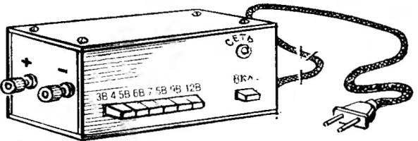
In the formulation of this problem soon followed. I hope it will be acceptable for other Amateur designers. Vedas s hull produced by the proposed method, get good-quality. Strength, elegance, moisture and heat resistance inherent in the base material of the insulator (and the PCB, phenolic paper or glass fiber), ideally complemented by the valuable properties of the conductive layer (foil), including the ability to serve as an electrostatic screen. In addition, the manufacture of such a case takes only an hour and a half (about 70 percent of the time is spent on propeica seams).
 Familiar to many hams, the situation: once the scheme is built, configured, but… to Squeeze it into some kind of “soap” not want to, but new to “diamond” the right frame there is neither time, nor forces. Had to find a way out of similar situations and me while in one of the publications, “Model construction” did not find a clue. It turns out that enterprising and slopestyle Siberians, which wrote the log, began the production of fine gift boxes of foil materials commonly used in the manufacture of printed circuit boards. Moreover, the simplest technology: the workpiece-scan in the field of future folds (from the base-insulator), they made cuts, and after giving it a box shape was probabaly foil joints.