As the power unit chosen was the well-known engine with forced air cooling Т200М scooter “Tula Tourist”. Unlike regular complete installed on it TO carb-28G, air filter ZID-4.5 and a homemade silencer. The torque from the motor to the wheels is transmitted by a chain transmission which includes the gear from the chopper feed “Volgar”. The use of such gear, in addition to improving traction characteristics, provided the cultivator an opportunity of movement and reverse, which increased its maneuverability. Reverse is activated by turning lever reverse shaft associated with a corresponding leash reducer. This shaft runs in three bearings mounted on the bracket of the steering brace and the frame. Each leg is equipped with a bronze (brass) bushing.
Speed switch lever, submitted to the steering strut and the United rockers and rods with the axis of the gear shift motor. The rocking sleeve mounted on the axle, welded to the strut to the steering wheel have an inner groove for gasket grease in them. In fact, the main focus wheel engine controls: clutch lever, lever throttle, and an electric switch.
The motor assemblies, the gear, the intermediate shaft and the support axle is mounted on the frame, welded from steel pipes of rectangular section, thick-walled angles and strips. The majority of frame parts in the manufacture of pre-connected together by bolts, and after trimming and the final Assembly has failed. Intermediate shaft and axle drive axle rotates in the bearings used in agricultural machinery. The tension of the first and last circuits is adjusted by changing the position of these supports, and secondary — special tensioner with a sprocket mounted on a bracket on the left side of the frame.
In the rear of the frame to the steering brace welded to the headstock of agricultural implements. Because it is one of the most loaded elements of frame construction, it had to strengthen the steel gussets and a thrust bearing. The bracket is made in the form of an inverted U-shaped profile (rectangular tube profile with cut upper wall).
Scheme of transmission:
1 — engine; 2 — asterisk is the leading (z=13); 3 — asterisk intermediate (z = 20); 4 — intermediate small sprocket (z =11); 5 — support bearing (11206); 6 — leading wheel; 7 — a support bearing (11307); 8 — sprocket (z = 12); 9 — sprocket (z = 44); 10 — reducer; 11 — sprocket counter shaft (z = 20); 12 — an intermediate shaft.
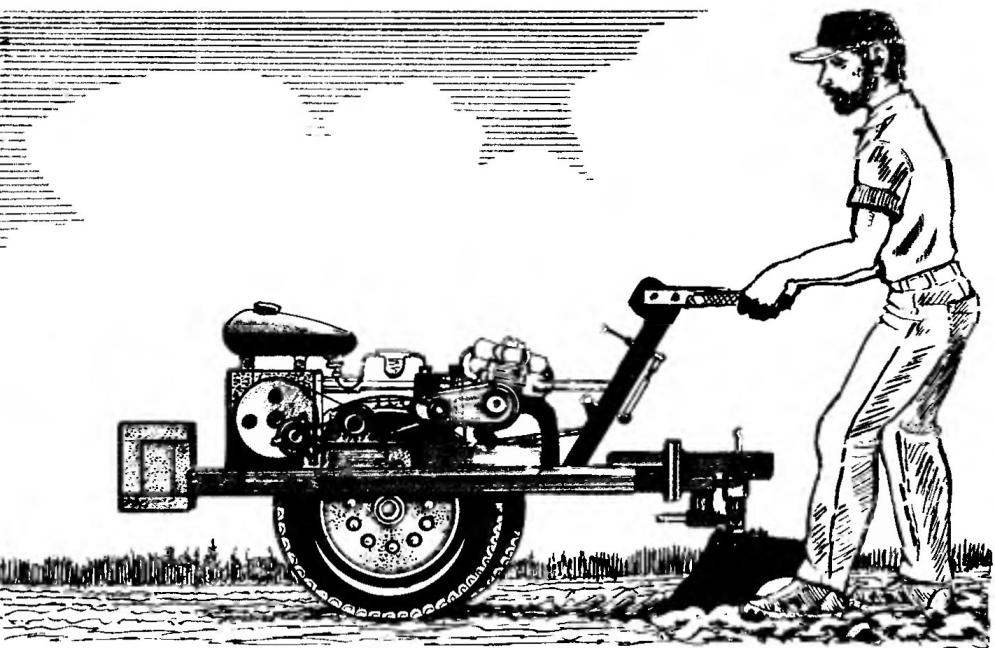
The layout of the tillers (all homemade items made of Vs):
1 — pull adjustable; 2 — rocking chair (the band 20×5); 3 — brace steering; 4 — cheeks on the stem (strip 40×5); 5 — wheel (steel 28×3); 6 — stem (pipe, 40x40x5); 7 — the switch of the engine; 8 — eyelets (sheet s5); 9 — shift lever; 10 — the lever of inclusion of a reverse; 11 —engine; 12 — carburetor; 13 — bantoustans; 14 — air filter; 15 — gas tank; 16 — drive (from the feed chopper “Volgar”); 17 — a shaft of switching reverse (pipe 32×4); 18 — basket balances; 19,58 — bearing mountings of the intermediate shaft of the transmission (11206); 20 — wheel driving (21″X13″x4″); 21 — a support bearing the wheel axle (11307); 22 — thrust fixed; 23 — the bearing (sheet sl0); 24— headstock agricultural implements; 25 — the mechanism of adjustment of a tilt angle of the plow, screw; 26 — bolt of the plow M16 (4x); 27 — a ploughshare; 28 — front plow (tube 36×3, L230); 29 — Board field (area 40×40); 30 — axle tilting mechanism of the plow; 31 —bolt M12; 32 — arm pawl (rod Ø10); 33 — the case of the tilting mechanism of the plow (pipe 45×7, L160); 34 — shank; 35 rocking dual (band 20×5); 36 —clutch lever; 37 — a bolt M10 (2 PCs.); 38 — arm “gas”; 39 — Klondike steering (sheet s5); 40 — washer; 41 — flange tilting mechanism of the plow (Ø115, the sheet s 15); 42 — the eye of the plow (sheet s7); 43 — bolt M20; 44,45 — flanges of the mechanism of rotation of the plow (Ø115, the sheet s 15); 46 — the case of the mechanism of rotation of the plow (pipe 46×5); 47 — bushing stopper; 48 the ring; 49 — the case of the stopper; 50 — sleeve rocking; 51 — axis rocking (rod Ø8); 52 — washer (4 PCs); 53 bolts MB; 54 — sprocket (z = 44); 55,57,61 —circuit; 56 — asterisk host (z = 13); 59 is a driven sprocket (z = 20); 60 — chain tensioner; 62 — sprocket (z = 12); 63 — bushing (bronze); 64 — the support shaft; 65 — washer; 66 — pin (Ø3); 67 — muffler.
Frame (all parts are made of Vs):
1 — beam transverse (rough 40x40x5, 2); 2 — solitaire (sheet s7); 3 — headstock agricultural implements (tube 50x50x4 cut top edge); 4 — shank mount plow (tube 60x40x5, L160); 5 — the tilting mechanism of the plow; 6 — axle (rod 030); 7 — longitudinal (pipe, 40x40x5, 2 items); 8 — steering brace (pipe, 40x40x5); 9 — bracket (area 32x32x3); 10 — shaft support switch reverse (38×4 pipe, 3). 11 — brackets engine mounts, front (sheet s7); 12 — mounting bracket engine rear (sheet s7); of 13.24— stand for the pillars of the intermediate shaft (area 50x32x4); 14— bracket chain tensioner (50x50x4 area); 15— stand (corner 50x50x5, 4 pieces); 16 — jumper (strip 50×7, 2); 17 — beam of fastening of a petrol tank (area 50x50x5); 18 — mounts gas tank (stripe s7); 19,20 — details of the top frame of the basket balances (strip 50×7); 21,23 — parts of the lower frame (the area 50x50x5); 22 — basket stand (corner 50x50x5); 25 — crossbar middle (area 50x50x5); 26 — longitudinal beam engine mounts (corner 50x50x5 cut a horizontal flange, 2 PCs.); 27 — beam medium (area 50x50x5).
The design of the plough has three swivel joints, allowing you to adjust the angle of the blade and during the maneuvers to throw it aside a u-turn around the horizontal axis. Required amount of penetration of the ploughshare into the soil by the farmer is aged using the steering wheel. To facilitate these steps, the motor-block is balanced by the counterweights of appropriate weight (steel or cast-iron ingots, cutting logs), placed in specially provided basket in the front of the frame.
The drive wheels of the motor-block is selected of sufficiently large diameter and width to provide less specific ground pressure and better maneuverability of the unit. If necessary to improve traction on wheels easy to put on the lugs of the chains.
Hopes the lens designer when creating tillers, fully justified. The unit was a great help in the hard work in the garden and has been successfully used on the master station, and the neighbor’s work.
V. KUDRIN
Recommend to read STOOL-TRANSFORMER This versatile stool which if necessary can turn into a small stable ladder, absolutely necessary in those apartments where there are high cabinets and mezzanines. To produce such a... MOSCOW BMW The idea is to make the car the most I had in those days, when "the Zhiguli""Muscovites" and even "the Cossacks" could be bought only after standing for many years in the queue. Then... 
 When plowing or tillage in the garden is easier to use a walk-behind tractor with mounted equipment. This is due to the fact that lands in the garden, usually small; in addition, not all beds need to plow. In such circumstances, traktorist difficult to maneuver and how easy is unfolding almost on the spot. E. Kulikov (der. Bornukovo, Nizhny Novgorod region) when doing the tillers, on the basis of these considerations.