The opening for the windshield in the front panel I customized to fit the frame of two-millimeter aluminum sheet. Then this frame is glued into the panel and it is inserted into the front glass of the car ZAZ-968. In the same way was made the rear and glazed panel.
The finished panel I cut the parting lines on the layout of the body and customized to the tubular frame. Panel to it was fastened with screws, choosing the gaps of the wooden slats with grooves and podkladyvaya them inside 4-6 layers of fiberglass. The joints between the panels were carved steps and was filled with strips of fiberglass on the glue.
Fig. 10. The installation of the adapter :
1 — front bracket-engine, 2 — adapter, 3 — adjusting screw 4 — adjusting hole, 5 — pinch snips.
The assembled body is completely plastered and sanded in preparation for painting. Irregularities were sealed with putty on the basis of the same epoxy glue by adding fillers: talc, aluminum powder and the like.
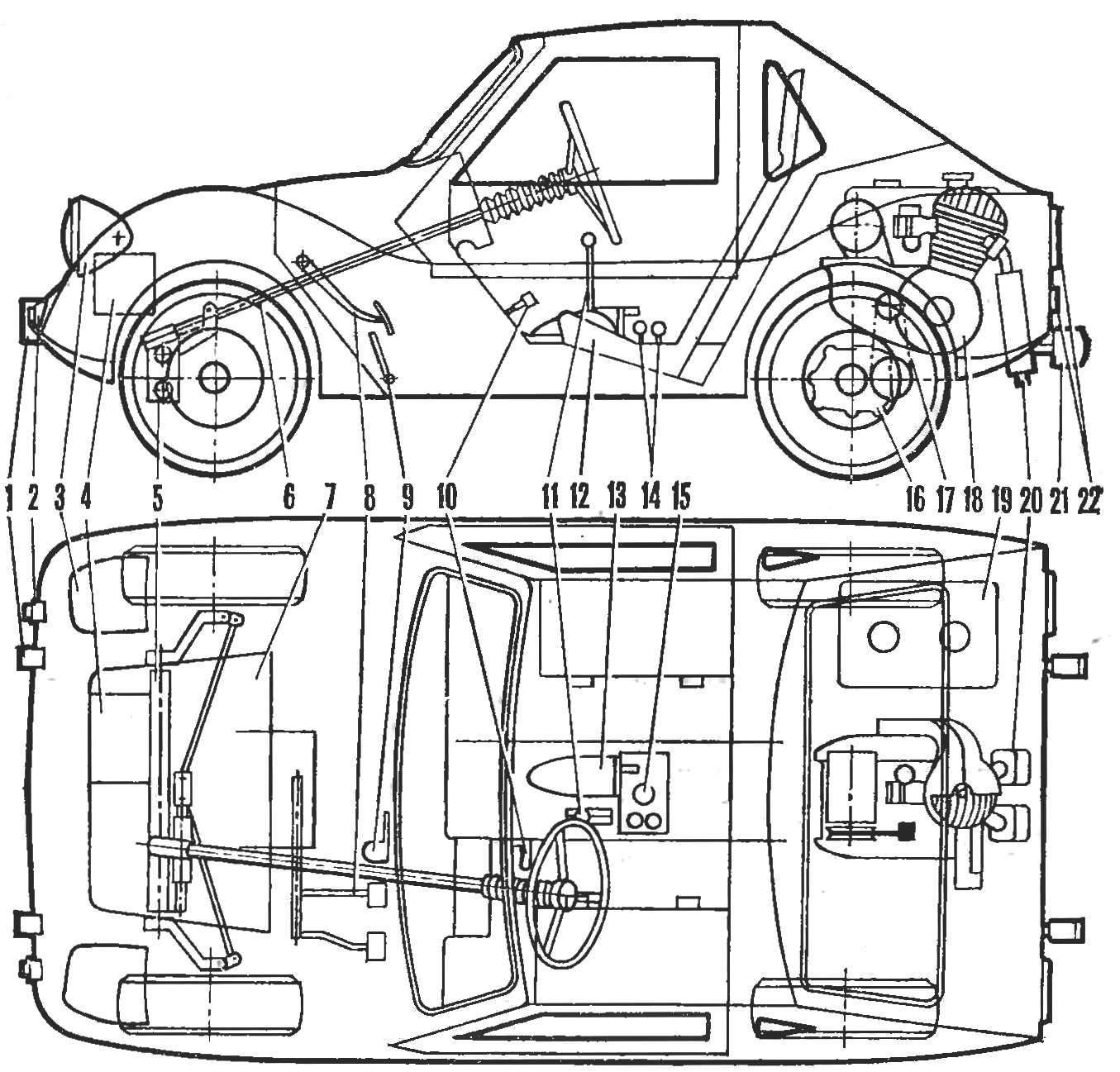
The skeleton of the body is assembled from thin-walled steel pipes, they are welded attachment points to the frame of vehicle: front, bottom and back support. Tubular design has the frame of the folding hood. If necessary, the latter can generally be removed, for example in the repair of the engine.
Fig. 11. The shift lever and reverse :
1 — lever, 2 — casing, 3 — sector gear with the drive 4 — sector reverse, 5 — pressure plate, 6 — finger, 7 — area of the vehicle frame, 8 — fork thrust reverse, 9 — plug the shift rod, 10 — a bracket of fastening of the lever, 11 — plug, 12 — spring retainer 13 and ball lock, 14 — pull the gear shift.
The main power element of the body — a rigid frame of steel pipes and corners. She carries a skeleton, hood, front axle, engine with under-eye frame and the differential, suspension rear wheels, trunk and so on. For mounting these units the fixing brackets, nodes and supports.
The front frame is mounted the axle of the sidecar, SZA, has been modified for drum brakes from a cargo scooter.
Fig. 12. Rear suspension :
1 — power transfer 2 — frame vehicle, 3 — arm, 4 — mount, 5 — panel, 6 — wheel hub 7 — eyelet fastening arm, 8 — bushing 9 — rubber liners, 10 — finger 11 — the case of the lower mount and shock absorber, 12 — edge 13 — eyes of the upper mount and the shock absorber, 14 — Klondike solitaire.
On the rear of the frame on a makeshift rubber pads mounted lodotra frame with the power plant from the scooter FDD is deployed to 180°. Front” on her mount adapter, offset vertically relative to the mounting bracket of the engine. Rear point — hinged: bracket, covering the collar of the tube sub-frame, allows a small rotation of the power unit in a vertical plane. It was made for tensioning the drive chain adjusting screw, which, being wrung out from a reference platform for the front bracket. lifts the engine. Fixation of the degree of tension of the chain is the collar and tie-rods (see Fig. 9 and Fig. 10).
The torque is transmitted single-row roller goal step 15,875 mm differential with reverse gear from a cargo scooter. The differential is suspended on four studs under the engine on rods and sub-frame. In principle it differs little from motocoaster — the same compact and reliable. However, to obtain the desired number of revolutions of the wheels had to make a new sprocket with 16 teeth.
Fig. 13. Mufflers :
1 — through bolt 2 — clamp, 3 — a casing of the silencer 4 — inlet flange, 5 — coupling nut, 6 — plate attachment to rear mounting bracket engine, 7 — ejector, 8 — perforated pipe, 9 — bottom, 10 to the exhaust pipe.
Transmission, as is known, is built directly into the engine, and reverse — differential. To manage them you must have two levers with the separate drive. I used a single drive switching gear, and reverse, which is much simplified control of the car.
The shifter in the cab is pivotally mounted between the two gear and reverse and is constantly pressed by a spring to the first. In the neutral position the sectors of the fixed balls, which under the action of its springs are in the grooves of the discs.
Fig. 14. Modified shock absorber :
1 — absorber, 2 — plates under the additional spring 3 — rubber buffer, 4 — spring shock absorber, 5 — extra
spring, 6 — cracker.
For reversing sector gear to translate the lever forward — include the first transfer. Then the lever returns to the neutral position (transmission in this case does not turn off) and again, but with a sector of the reverse, forward serves, including reverse.
Other engine controls — gas pedal, clutch and the ignition switch is usual, regular.
Fig. 15. Hub rear wheel :
1 — driveshaft with u-joint, 2 — the axis of hub 3 — hub body, 4 — bearing 5 — flange of the brake shield, 6 — disc wheel And brake drum, 7 — segment dowel, 8 — a nut of fastening of the disc 9, the inner rim 10 to the brake drum 11 is the outer rim, the 12 — brake pad, 13 — brake shield.
The layout of the power plant, Matousec dictated and replacing one of the factory muffler on a homemade two — the first did not fit in the hood space.
Mufflers welded from sheet steel. Connect them to the exhaust ports of the cylinders (swivel nuts), and to the mounting bracket of the engine
(insert sample). It should be noted that the exhaust sound from homemade silencers louder than factory. Probably the impact of their small internal volume. However, engine power is not affected.
Fig. 16. The front wheel hub :
1 — roller, 2 — gland, 3 — knuckle, 4— additional flange 5 — bolt brake plate, 6 — hub, 7 — backing plate, 8 — brake pad, 9 — drum, 10 — pinch bolt, 11, 12 rims wheels 13 — ring spacer.
Rear axle assembled from two homemade independent suspension with longitudinal swing arms. The levers of thick-walled steel pipe d 32 mm I installed bearings in the ears — the points of fastening to the vehicle frame.
To the opposite ends of the arms welded to the hub of the rear wheels and lower the attachment points of the shock absorbers, which is a cylindrical body with an axial bushings under the bolts and rubber inserts.
Fig. 17. The layout of the actuator retractable headlamp :
1 — bearing, 2 — axle housing 3 — lamp housing, 4 — screw fixing shelves, 5 — the rope of speedometer, 6 — arm drive, 7 — thrust, 8 — lever 9 — bearing housing shaft, 10 — spacer sleeve from the shaft 11 of the gearbox casing, 12— panel mount lights, 13 —headlight
The upper mounts of shock absorbers is the tabs on the gussets, are welded to the tubular elements of the frame of the car.
Hub and axle of the rear wheels from a cargo scooter; rim and brake components from motorized FDD. In a single unit they are connected to the flanges and disks.
Fig. 18. The drive mechanism of the headlights :
1 — arm, 2 — flywheel, 3 — case fans 4 — the rope of speedometer, 5 — cable sheath, 6 — worm shaft 7 is a worm wheel, 8 — housing, 9 — clamp lever, 10 — lever 11 — bearing housing shaft, 12 — shaft 13 — spacer.
Rear axle “Mouse-2” is heavily loaded, and the elasticity of the shock absorbers of the motorcycle “Ural”, as it turned out, insufficient. So they had to modify to install additional springs that I made from one of the rear spring of the car ZAZ-968, cutting her gas burner. Sheared edges while they were hot, buckled, and then grind on the grinder for a precise fit in the dish.
The more complex the alteration the shock absorbers were not exposed. I removed only the outer covers. And dirt from falling on the rods, used protective covers made of thin canvas.
Fig. 19. Sprocket differential .
Power axles with cardan joints — also from a cargo scooter. But since the track “Mouse” wider, then they had to be lengthened. The axle shaft I cut in half and pressed in a steel sleeve. The length and fit them in place, welded to each other.
Front wheel is assembled from parts chassis sidecars, SZA and SZD. To connect them together I machined the extra flanges and ring spacers. Of suspension components (except hubs) were not modified. A hub only grind in three places as shown in the figure.
A curious element of my car can be considered retractable headlights. Such are sometimes found in improvised structures. In the afternoon, when there is enough light, hid headlight in the engine compartment, in the evening time they push out.
The lights I have with manual transmission (eventually it will be replaced by electric) installed in the cockpit. From the turntable to a worm reducer with a gear ratio of 1 : 80 stretches the cable of the speedometer in the shell. Further, from a worm wheel gear rotating the shaft, hidden in the spacer sleeve, through the levers and the thrust is transferred to the housings of the headlights, and they are put forward. They are governed by the offset shelves, which are fixed then the side screws.
V. VESELOV, Kholmsk, Sakhalin region.
Recommend to read UNKNOWN CELEBRITY Flying boat POTEZ 452. In the early 1930-ies of the French aviation firm Aeroplanes Henri Potez ("Aeroplanes Henri Poteza") built a small flying boat Potez 452, which has become one of... FAMILY, UNIVERSAL For many years now, I constantly write and read the magazine "modelist-Konstruktor". I was particularly interested in the materials, which describes autocostruzione. But until recently... 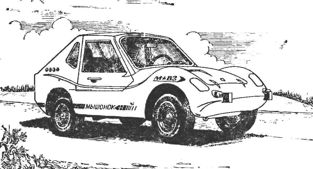
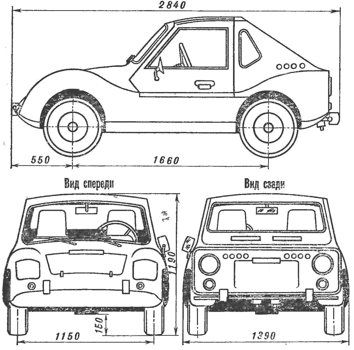
 The first little micro-car “mouse” I built for my kids. As a result, I accumulated some experience of designing and has already planned not as a child, and “adult” car. Called it “mouse-2”. Built a long time, or rather, not so much built, how many were looking for the necessary parts. This, in particular, due to the use of “Mouse-2” mechanical brakes (now I change them for hydraulic). Design drawings and the construction was carried out simultaneously, although the basic parameters of the “Mouse-2” was thought out by me in advance.