“Commander” (the so-called new paraglider) has surpassed the wildest expectations of designers.
Dome it easy to lift and hang over the pilot, providing the necessary few seconds to run. During the run the dome occupies a stable position over the pilot, and it rolls easily eliminated with bodegom and levantou.
Flight “Commander” — a pleasure. Overhead — strong, solid wing without any preconditions to the folding. “Drakoulious” this glider we appreciated after a rookie in a single flight for a long time hung with a fully tightened brakes and the other rocked the dome on the pitch as even test pilots do not shake. And nothing is flying! With the advent of “Commander” to teach and to learn to fly it became easier. More and more people prefer this reliable and quiet machine for Amateur flights on weekends and during the holidays. Moreover, the quality and speed allow to make not only floating, but even Shuttle flights.
And now more about how to design a glider.
Where do you start? In the first place put a problem or formulate the basic requirements which must be met for a training glider. And they are as follows:
— easy start and landing;
— reliability, stability and “drakoulious”;
— good (but not excessive) maneuverability;
— wide range of flight speeds;
— small speed reduction so that you can soar.
As always in aviation the requirements are very contradictory. The first and second paragraphs it is easy to provide a low elongation and a thick profile, but such is unlikely to satisfy other requirements. So the designers had to work hard.
We started with the choice of the form in the plan. Here, as best suited the ellipse (minimum inductive reactance), or a figure close to it in form (Fig. 2).
The area of the glider was chosen taking into account the specific load on the wing q. According to the statistics, there is a range of values of q(3 — 3.8 kg/m2 ) used for training paragliders. When range limits are a compromise between speed reduction (more space — less speed flight and lower) and the stability of the glider (less speed — less pressure in the dome and it is easier to lose stability).
Takeoff weight system pilot — glider is determined by the formula:
Musl. = M0 + MSN (1),
where: M0 is the mass of the pilot, MSN — weight of equipment (approximately 15 kg).
Basic technical data of paraglider “commander”
Based on the weight of the pilot 80 kg, and the unit load q=3,4 kg/m2 (mid range) was obtained wing area of the glider:
The choice of the aspect ratio (the ratio of the square of the length of the wing to its area) significantly affects the characteristics of the glider: an increase in the elongation reduces the inductive reactance and increases the aerodynamic qualities of the wing, but this reduces the safety of the flight due to the fact that a narrow wing is more susceptible to folding, but also makes it difficult to start and landing.
It was decided to stay on the elongation λ= 4,8. Although it is big, but we were hoping to achieve a good stability of the wing and its resistance to folding due to the new profile. Wing length (L) determined by the formula:
As an initial wing shape in a plan adopted half of the ellipse, whose area is equal to:
where a, b are big and half minor axes of the ellipse.
Hence, taking a = L found the size of the Central chord b:
The number of ribs in the wing determines the quality of its surface, the rate of filling of the dome with the folding and adaptability of the glider in production. After analyzing various design options with all the working (power) or secondary ribs (Fig.2) it was decided to choose the first option as the more appropriate concept training paraglider, that is, to make 37 sections (38 power ribs), and only on consoles to use two auxiliary ribs (Fig.4).
Line length affects the strength of the glider and the tension of its surfaces. The scheme of branching strop determine their total length. Analysis of possible variants of branching under the condition of minimal total length of the sling showed that the best option is when the lines of the first two ranks (“a” and “b”) of each wing are reduced to respective separate free ends (Fig.1), and the line “C” and “d” (Fig.3).
The most important work in the design of the dome is aerodynamic calculation. New profile (Fig.5) with the characteristics of HS max = 28% and C Max = 17%, established on the basis of the proven profile of the paraglider Grand, has a characteristic “belly”. It is stable at low angles of attack, which is very important for the safety of the paraglider. Stall characteristics of the profile was successful.
Was carried out painstaking work on the distribution of geometric and aerodynamic twist, which found a compromise between stability, controllability and quality.
To obtain the upper parts of the dome were used software*.
So, what happened?
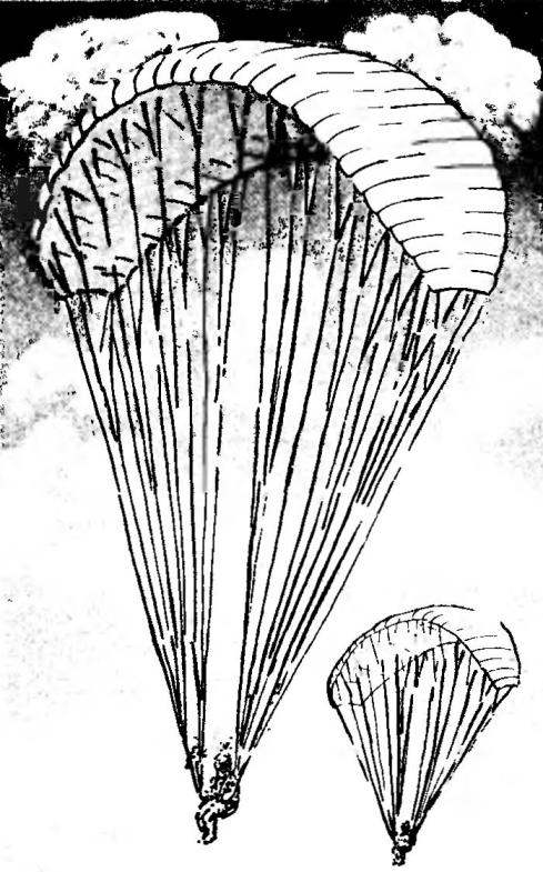
Fig.1. Paraplan “Commander”:
1 — cloth dome top; 2 — air intake; 3 — panel dome bottom; 4 — loose ends (tape LDP-25-1000, L500 — 520); 5 — the system suspension; 6 —loop fastener lanyard to the dome (tape LTK-15-185); 7 — line of the upper tier; 8 — slings of the second tier; 9 — line lower layer; 10— the line is of lower layer cantilever group; 11 —lateral line; 12 — ring; 13 — loop control — brake (tape LTCC-25-600); 14 — carabiner climbing; 15 — line management.
Fig.2. Selecting the shape of the wing of the glider.
Fig.3. Design options dome:
a — rib power; b — with auxiliary ribs; 1 — panel bottom; panel 2 top; 3 rib power; 4 — slings; 5 — rib support.
Fig.4. The dome of the paraglider (spread out, VCD bottom):
1 — rib; 2 — panel top; 3 — reinforcements of the ribs (Dacron); 4 — slings; 5 — panel bottom; 6 — line control; 7 — loop fastener straps.
Fig.5. Wing profile and its characteristics:
Max — the maximum thickness of profile; b — the profile chord; XC max — coordinate of the maximum profile thickness;
Fig.6. Suspension system (schematic side view, the pockets and the elements of the active protection system and rescue are not shown):
1 —belt harness system; 2 — cover, seat inner (two layers avisenta + foam s 15); 3 — carabiner climbing; 4 — seat cover outer (avizent); 5 — stiff back (plastic); 6 — Board seat (plywood s 10).
Fig.7. Harness system:
1 – strap the main circular: 2 rib; 3 — waist circumference; 4 dorso-shoulder; 5 — loop fasteners emergency parachute: 6 — loop Adjuster (nylon-cord Ø 5); 7 — unit of accelerator; 8– jumper chest with ring; 9 – ring buckle (7 PCs); 10 — ring buckle with a jumper (7 PCs); 11 leg circumference; 12 – jumper back-shoulder girth.
Fig.8. Base harness systems:
1 — jumper chest; 2 — the strap main circular; 3 — jumper back-shoulder girth; 4 — circumference of the waist; 5 — dorsal girth-shoulder; 6 — base (single or backpack avizent fabric); 7 — bulwark (double avizent with a gasket made of polypropylene, s10); 8 — pocket for Board seats (avizent); 9 — foot girths.
Fig.9. Scheme loops of the system (bottom view, within the specified length of the sling):
1 — slings minor (1st and 2nd tiers); 2 — the lateral line; 3— line console group; 4 — slings basic.
Fig.10. Back-shoulder girth:
1— loops (LTK-44-1600, L2890); 2 — amplifier (LTK-26-600, L135, 2); 3 — lining (LTK-44-1600, L180, 2 PCs.).
Characteristics of the stitches used in the stitching of the tapes LTK-44-1600
Fig.11. The most comfortable position of the pilot in the chair.
Fig.12. The strap of the main pie:
1—tape straps (LTK-44-1600, 1Л880); 2 — loop (ЛТК44-1600, L195); 3 — ring buckle (parachute kit, 2 PCs.).
Fig.13. Jumper back-shoulder girth:
I 1 — ring buckle (parachute kit, 2 PCs); 2— feed jumper (LTK-44-1600, L600).
Fig.14. Girth belt:
1 — ring buckle (parachute kit, 2 PCs); 2 — tape wrap (LTK-44-1600. L830).
Fig.15. Jumper chest with the ring:
1 — ring buckle (parachute included); 2 — feed jumper (LTK-44-1600, L685); 3 — loop (LTK-15-185, L120); 4 —small block accelerator.
Fig.16. Jumper chest:
1 — tape-jumpers (LTK-44-1600, L770); 2 — loop (LTK-15-185, L120); 3 — lining (LTK-44-1600, L145); 4 — small block accelerator.
The wing of the paraglider is made of special air-tight fabric and is sewn from two panels (Fig.4). Each section has a dome top, bottom panels and ribs. The leading edge of a panel not connected to form air intakes. To distribute air along the length of the wing in case of uneven filling of the ribs have holes and in the zones of attachment of the sling and the front edge of the reinforced stripes of Dacron.
Slings (Fig.9) is made of SVM cord of braided nylon. Their ends represent the loop length of 55 — 70 mm. Mounted slings “noose”, from the top to the bottom (Fig. 1). Moreover, their diameter increases from 0.8 mm to 1.6 mm in the same direction. Slings of lower layer attached to the rings are all made of tape LDP-25-1000 and have three rows. The toggles are fixed on one sling attached to the brake. The free ends have “trimmers” and the accelerator, which allows to change flight speed in a wide range. However, the use of them is recommended only for experienced pilots.
At a certain stage of development of paragliding became clear that the desire to fly faster, higher and farther all cannot be achieved only by the design of the wing of the glider. There was a question about creating a new suspension system that meets the requirements of the pilots in the first place, the ergonomics and flight safety. This resulted in the inclusion in the suspension systems of a number of new elements and the upgrading of traditional nodes.
Depending on the class of the modern suspension system consists of a harness system, seats, pockets for gear and equipment, system protection and recovery (Fig.6).
The harness system (Fig.7) connects the pilot with the glider or the parachute in the case of its application. Its basic element is “framework”, made of durable nylon tapes, which comprises: a circular main strap, back strap-shoulder, leg and waist straps, and chest strap. The circular strap using the two carabiner (like mountain climbing) is connected with the free ends of the glider.
Important here is the distance between the point of attachment of the free ends and the center of gravity of the pilot. It is usually seeking to maximize, thus reducing the time, tipping a pilot ago when working with the accelerator or when flying in turbulent atmosphere.
The chair is designed for uniform distribution of load on the body of the pilot, provide comfort and protect him in a collision with the ground. It can accommodate the pockets, and also system of protection and rescue.
Convenient operating position for the pilot, in which he feels the least muscular tension and is easier to tolerate the overload (acceleration), when the deviation of the trunk back to the angle 16-18°.
Seat width is calculated by the maximum width of the pelvis of a person taking into account some margin for clothing. On average it is equal to 390 — 450 mm. the shape of the back of the chair, its height and width ensure proper and comfortable position of the pilot. Seat along with a backrest covered in soft cushioning material is raised to release the tension the harness on the body of the pilot and improving the ventilation in the back.
Glider — aircraft. So he, like most of his “older brothers”, is supplied by system of protection and rescue. They are divided into active and passive. The first is the rescue parachutes, pneumatic shock absorbers, which are filled with compressed air after the introduction of the pilot action of the parachute. A second Board and a rigid seatback, the pneumatic shock absorbers filled before the flight.
On “Commander” are used in suspension systems of the type “classic” or “Pro”, meet the highest requirements.
That’s all. At first glance it seems that this device is not very complicated. But all who choose to make their own glider, I highly recommend to tests to show its experts. And it would be nice to have the first flights to take under the supervision of an instructor.
I. VOLKOV, the head of the club “Vector”
Recommend to read The reasons for the failure of the Ipad Many people when buying a new and advanced gadget I hope for a long life, but in reality it is not so. Due to the fact that the tablets are technically complex device that causes of... ON A MOTOR BOAT WITH A BREASE! For those living near water, a motorboat is no less important than a motorcycle or a car: people use it to commute to work, visit neighboring villages, or go shopping in the district... 
 At first glance, what could be simpler than a training glider? A small lengthening of the wing profile is thick, the straps are short. The small set of characteristics, it would seem, is obliged to ensure that the novice pilot is quiet and comfortable flight. That may be so, but, unfortunately, the beginner quickly get tired of just plan, he wants higher and higher. And a struggle begins between the flight characteristics of the machine and the safety of the flight.