Typically, garage doors have two heavy leaves that open outward. Every car enthusiast knows how much trouble they cause, especially in winter. Snow accumulates on the area in front of the garage, ice freezes on the doors, lock, and handles. You have to tinker a lot to get the car out.
By abandoning the traditional scheme, the Bulgarian engineer Vasil Karaleev avoided these difficulties.
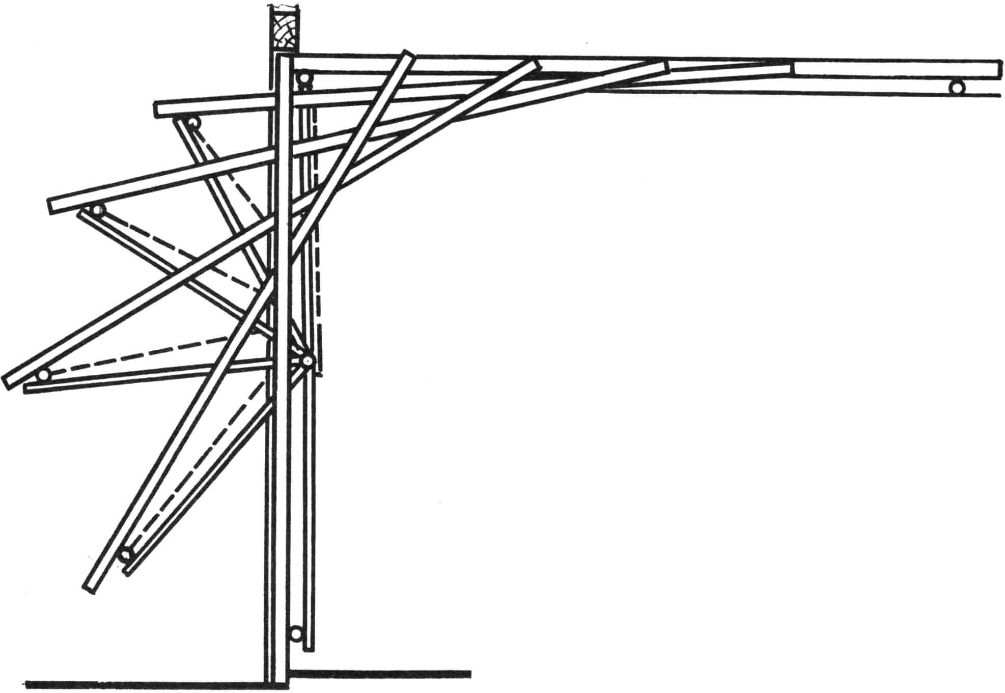
The gates he offers have one leaf equipped with a device that lifts it up: in this position it is parallel to the ceiling. When lifting it, you do not have to exert much effort, since the weight of the gate is compensated by two cylindrical springs. The sash is lifted using a system of levers with springs and rollers that roll along guide rails. In this case, the lower edge, moving in an arc, turns out to be facing outward, and the upper, rolling along the guides, goes inward. Along with the movement of the gate, the state of the compensating springs also changes: in the closed position of the gate they are stretched, in the open position they are almost free.

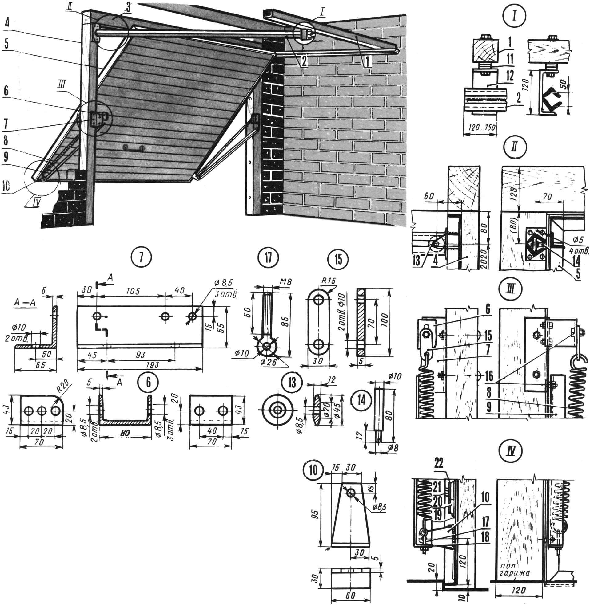
The entire structure consists of a gate frame, a lifting leaf and an opening mechanism. The box is assembled from two vertical wooden beams with a cross-section of 120X80 mm, a length of 2300 mm, and a horizontal beam of the same cross-section, a length of 2750 mm, connected to each other using metal plates or squares. The lower ends of the box posts are recessed 20 mm into the concrete base. The box is fixed in the opening on metal pins Ø 10X200 mm.
The gate leaf is assembled from a frame with stiffening ribs from a corner and a board panel sheathed on the outside with sheet steel. The shield is attached to the frame using furniture bolts with metal strips instead of washers. The frame has dimensions of 2500X2100 mm and is made of angle rolled steel 35X35X4 mm. Stiffening ribs from the same corner can be located both vertically and horizontally, with fastening from the outside of the frame or from the inside, through the shield.
The main fixed support of the mechanism consists of a corner 65X65X6 mm with a length of 193 mm. On one of its shelves two Ø 10 mm holes are drilled for fastening to the vertical posts of the box. The other shelf of the angle has three holes Ø 8.5 mm: the top two are necessary for installing the spring bracket, and the bottom one is for hanging the lifting mechanism lever on a hinge. The fixed support for the spring is a bracket made of 80X43X5 mm channel, 70 mm long. To attach it, three holes Ø 8.5 mm are drilled in one shelf. The spring is connected to the bracket through an adjusting plate, which is cut from a strip of steel with a section of 30X5 mm. The spring can be used ready-made, for example, decommissioned from a combine: it should have an internal Ø 30 mm and 60 turns of a rod Ø 7 mm. The extreme turns are made in the form of hooks located in the same plane. A tension regulator is attached to the lower end of the spring. The latter is made from steel rod Ø 8 mm. A ring is provided on one side, and an M8X60 mm thread is cut on the other.

1 – horizontal beam of guide rails, 2 – guide rail, 3 – horizontal beam of the gate frame, 4 – vertical post of the frame, 5 – gate frame, 6 – spring mounting bracket, 7 – hinge angle, 8 – spring, 9 – lifting lever mechanism, 10 — lever bracket, 11 — adjusting washers, 12 — channel, 13 – roller, 14 – roller axis, 15 – adjusting plate, 16 – hinges, 17 – spring tension regulator, 18 – adjuster plate, 19 – steel sheet, 20 – shield board, 21 – furniture bolt with nut, 22 – metal plate.
The lower hinge assembly consists of an angle with a Ø 8.5 mm hole, welded to the sash frame at a distance of 120 mm from the bottom edge to the axis of the hole, which serves to install the lifting mechanism lever on the hinge. A steel plate measuring 50X40X5 mm with a Ø 8.5 mm hole for the spring tension regulator is welded to the end of the lever.
When lifting, the upper edge of the gate moves along guide rails under the ceiling. Each rail is made up of two steel corners 40X40X4 mm, 2100 mm long: they are welded with one edge of the shelf so that the internal distance between the tops of the corners is 50 mm.
The finished rail is welded at one end to a steel plate measuring 80X60X4 mm with four Ø 6 mm holes for fastening to the vertical posts of the box. The distance between the center line of the rail and the bottom edge of the horizontal beam of the box should be 80 mm. To the other end of the guides, at a distance of 120… 150 mm, a section of channel 120X52X6 mm, 100 mm long, is welded, attached with an M10 bolt to a horizontal beam on the ceiling, with a cross-section of 100X100 mm. The position of the guides must be strictly horizontal, which is achieved by placing washers between the channel and the beam.
Adjustment of the rising gate is carried out using the spring tension screw. In this case, it is necessary to ensure that the sash can remain motionless in any position. To do this, when installing it in the upper, intermediate or lower position, tighten or loosen the spring tension adjuster nut. If necessary, you can change the upper spring mounting point by moving the adjustment plate hinge higher or lower.
The gates are locked with locks located in the corners of the gate leaves. In the middle of its lower part there is a handle about 20 mm high.
Based on materials from the “Direct Yourself” newsletter, Bulgaria


